In multi-axis magnetic field systems, one of the most common sources of experimental error is not hardware performance, but coordinate system misalignment.
Researchers often assume that “X, Y, Z” axes are self-evident.
In reality, without a clearly defined coordinate system, even high-precision measurements can become inconsistent or misleading.
This article explains how to define and verify coordinate systems in magnetic field experiments so that results remain physically meaningful and reproducible.
Why Coordinate Systems Matter in Magnetic Experiments
Magnetic field measurements are inherently vector quantities.
A magnetic field is not just a magnitude—it has both direction and orientation.
If coordinate systems are inconsistent between:
- magnet system
- sample orientation
- measurement sensors
then experimental data may:
- appear rotated or inverted
- produce inconsistent results across runs
- become difficult to compare with theory
Background on coordinate systems:
https://en.wikipedia.org/wiki/Coordinate_system
Defining a consistent coordinate system is therefore essential.
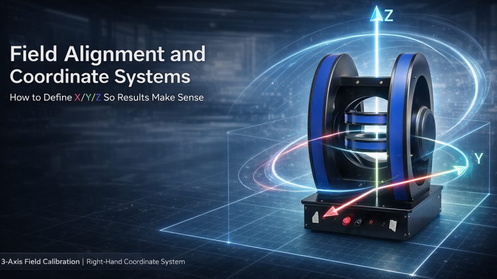
The Right-Hand Coordinate System
Most magnetic field systems use a right-handed coordinate system.
In a right-handed system:
- X, Y, Z axes follow the right-hand rule
- X × Y = Z
Background reference:
https://en.wikipedia.org/wiki/Right-hand_rule
This standard is widely used in physics and engineering.
However, problems arise when:
- different subsystems use different conventions
- axes are flipped during installation
- documentation is unclear
Where Misalignment Comes From
Coordinate inconsistencies often arise at system boundaries.
Typical sources include:
1. Mechanical Mounting
The physical orientation of the sample holder may not match the assumed coordinate system.
2. Sensor Alignment
Magnetic field sensors may be rotated relative to the magnet axes.
3. Software Definitions
Control software may define axes differently from hardware labeling.
4. Assembly Variations
During installation, even small angular misalignments can lead to systematic errors.
Defining a Clear Reference Frame
To avoid confusion, experiments should define a single reference coordinate system.
This includes:
- origin location (usually the center of the field region)
- axis directions (X, Y, Z orientation)
- rotation conventions
A clear definition ensures that all components reference the same frame.
Using Rotation Matrices for Alignment
In real systems, perfect alignment is rarely achieved.
Instead, coordinate transformations are used.
A rotation matrix describes how one coordinate system relates to another.
For example:
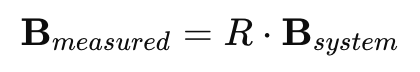
Where:
- R is a rotation matrix
- B is the magnetic field vector
This allows conversion between:
- sensor coordinates
- system coordinates
- sample coordinates
Using transformation matrices ensures consistent interpretation of vector data.
Practical Alignment Procedure
A reliable alignment workflow typically includes:
Step 1: Define System Axes
- Clearly label X, Y, Z on the magnet system
- Confirm right-hand orientation
Step 2: Align Sample Holder
- Ensure the sample is mounted relative to the defined axes
- Use mechanical fixtures to maintain orientation
Step 3: Calibrate Sensors
- Measure known field directions
- verify sensor axis alignment
Step 4: Perform Test Measurements
- apply field along each axis
- confirm expected response
Step 5: Apply Corrections
- use rotation matrices if needed
- document transformation parameters
Common Mistakes to Avoid
Even experienced users can fall into these traps:
- assuming axes are aligned without verification
- mixing coordinate conventions between software and hardware
- ignoring small angular misalignments
- failing to document coordinate definitions
These errors can lead to incorrect interpretation of experimental results.
System-Level Alignment in 3-Axis Magnet Systems
Three-axis magnet systems require particularly careful alignment.
Important considerations include:
- orthogonality of coil axes
- independent control of each axis
- accurate sensor placement
Cryomagtech supports three-axis electromagnet and Helmholtz coil systems with attention to coordinate definition, alignment, and calibration workflows.
👉 Product Link Placeholder – 3-Axis Electromagnet and Helmholtz Coil Systems
Proper alignment ensures that vector magnetic fields are generated and measured as intended.
Key Takeaways
- Magnetic fields are vector quantities that require consistent coordinate definitions
- Right-handed coordinate systems are the standard convention
- Misalignment can occur in mechanical, sensor, and software layers
- Rotation matrices allow correction of coordinate mismatches
- Clear documentation and verification prevent experimental errors
In multi-axis magnetic systems, correct results depend as much on coordinate definition as on hardware performance.