
High-uniformity Helmholtz Coil and Helmholtz Coil System solutions for research institutes, universities, test laboratories, and sensor teams—engineered to generate controllable uniform magnetic fields (DC and AC), simulate magnetic environments, and perform reliable sensor calibration.
If you came here from a Google Ads search like 3 Axis Helmholtz Coil, Triaxial Helmholtz Coil, Uniform Magnetic Field Generator, Geomagnetic Compensation, or Magnetometer / Hall Probe Calibration, you’re in the right place.
👉Get a Quote Now – 24h Response Guaranteed
Best fit for your project if you need:
- A known, repeatable uniform magnetic field in an open working volume (not a tight pole gap).
- Earth-field cancellation / geomagnetic compensation, or a programmable “magnetic field simulator” for low-field environments.
- Calibration workflows (coil constant B/I, field mapping, and acceptance deliverables) that you can actually verify in your lab.
Uniform Magnetic Fields Without Guesswork
What a Helmholtz coil is and why it stays the “default choice” for uniform field generation
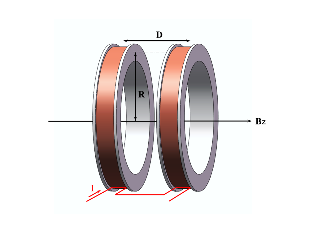
A Helmholtz coil is a pair of identical coils placed coaxially, carrying the same current in the same direction. When the coil spacing equals the coil radius (the Helmholtz condition), the field non-uniformity near the center is minimized—creating a region of nearly uniform magnetic field that is widely used in precision experiments and calibration setups.
A practical engineering takeaway (no mysticism involved): for a classic circular Helmholtz pair, the center field scales roughly with coil turns and current, and inversely with coil radius (B ∝ n·I / R). This is why “bigger uniform volume” and “very high field strength” tend to fight each other on cost and thermal design.
Why customers buy Helmholtz coils (instead of building DIY coils)
In real labs, the biggest hidden risks are usually not “the physics”—they are repeatability problems: coil alignment, centering, fixture offsets, thermal drift, and background-field interference. A millimeter-level positioning error can dominate your accuracy budget even when the coil is “high-uniformity” on paper.
Cryomagtech’s Helmholtz coil approach focuses on the full measurement loop: coil geometry + current source + optional feedback + practical acceptance testing (coil constant B/I and mapping plan), so your setup can be validated—not just admired.
Select the Right Helmholtz Coil Configuration for Your Test Setup
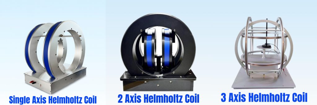
1D Helmholtz coil
A 1D (single-axis) Helmholtz coil generates a uniform field along one axis. It is often used for:
- Magnetometer and Hall probe calibration in a defined uniform region.
- Cancelling or applying a controlled bias field (including Earth-field-related offsets).
This is typically the most cost-effective way to start when your DUT only needs one controlled axis.
2D Helmholtz coil
A 2D (dual-axis) Helmholtz coil uses two orthogonal coil pairs to generate vector fields in a plane (e.g., X and Z). It’s a common choice when:
- Your sensor needs orientation-dependent testing (but full 3D isn’t required yet).
- You want to separate “bias” and “excitation” axes in a clean, programmable way.
3D / 3 Axis / Triaxial Helmholtz coil
A 3D / 3 Axis / Triaxial Helmholtz Coil uses three orthogonal coil pairs to generate a controlled magnetic field in any direction—often the simplest “magnetic field simulator” approach for sensor teams and magnetic environment labs.
This is a standard approach for orientation-dependent probe calibration and vector-field generation; one published example designs a 3D Helmholtz system to generate fields up to the mT range with controlled direction for Hall probe calibration.
Quick comparison table: 1D vs 2D vs 3D
Table title: 1D / 2D / 3D Helmholtz Coil Configuration Selection
| Configuration | What you control | Typical buyer goal | What increases complexity |
|---|---|---|---|
| 1D (single-axis) | One field component | Fast calibration / simple uniform field | Larger uniform region, higher field, long duty cycle |
| 2D (dual-axis) | Two orthogonal components | Vector tests in a plane | Cross-axis coupling definition; matching two channels |
| 3D (triaxial) | Full vector field | True 3D orientation testing / geomagnetic compensation | Mechanical orthogonality, multi-channel control, thermal/space planning |
Circular vs Square Helmholtz Coils
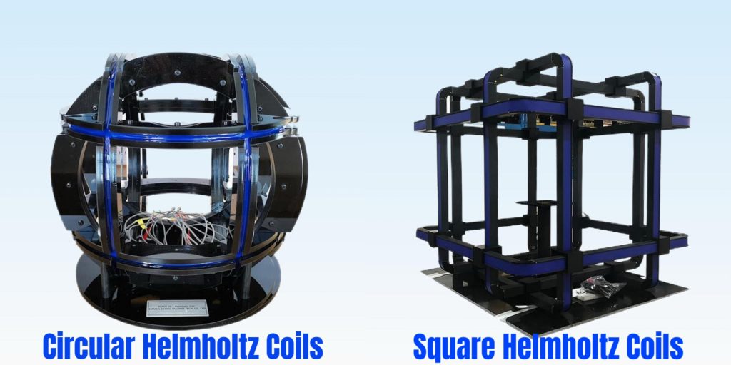
Both circular Helmholtz coils and square Helmholtz coils can generate excellent uniform fields when correctly designed, assembled, and validated. Your best choice depends on working space, fixtures, and integration, not just field math.
Circular Helmholtz coil
Choose a Circular Helmholtz Coil when you want:
- Clean symmetry and classic Helmholtz geometry (widely used in metrology and calibration setups).
- Efficient use of conductor length for a given radius (often favorable for compact bench-top systems).
Square Helmholtz coil
Choose a Square Helmholtz Coil when you want:
- A larger practical workspace for “boxy” DUTs (chambers, fixtures, electronics enclosures, larger assemblies).
- Large-aperture test volumes where frame-based structures and straight segments simplify mechanical integration.
Square coil cages are also widely used in large-scale calibration facilities for magnetometer sensors, emphasizing working-space practicality and integration.
Quick selection table: Circular vs Square
Table title: Circular vs Square Helmholtz Coil Selection
| Geometry | Best when you care most about | Common use cases |
|---|---|---|
| Circular Helmholtz Coil | Symmetry, compact bench-top setups, classic Helmholtz condition | Sensor calibration, uniform bias fields, lab test rigs |
| Square Helmholtz Coil | Larger usable workspace, easier mechanical fixture/chamber integration | Geomagnetic compensation cages, larger DUT testing, EMI/magnetic environment simulation |
Standard Helmholtz Coil Models
Cryomagtech maintains a standard product range for common lab and sensor-calibration needs, covering circular and square Helmholtz coils, and 1D / 2D / 3D configurations.
This section is intentionally transparent: standard models are for fast matching, while performance boundaries (uniform region, duty cycle, AC frequency, and integration constraints) are handled through engineering review when needed.
Standard range: typical single-axis circular Helmholtz coils
Below is an example of how we express “standard” in a way a lab can validate: coil size, center field target, and defined uniform-region diameter at specific uniformity levels.
Table title: Typical Parameters for Standard 1D Circular Helmholtz Coils (HC Series)
| Model | Coil radius (mm) | Center field (Gauss) | Uniformity target (%) | Typical uniform region diameter (mm) | Typical power range (W) | Approx. weight (kg) |
|---|---|---|---|---|---|---|
| HC7-50 | 70 | 50 | 0.5 / 0.1 | 28 / 21 | 24–120 | 5 |
| HC7-100 | 70 | 100 | 5 / 1 | 45 / 35 | 50 | 7 |
| HC10-10 | 100 | 10 | 1 / 0.1 | 50 / 30 | 10–24 | 3.5 |
| HC10-50 | 100 | 50 | 0.05 / 0.01 | 20 / 10 | 50–180 | 9 |
| HC10-100 | 100 | 100 | 0.5 / 0.1 | 40 / 30 | 100 | 15 |
| HC15-50 | 150 | 50 | 0.05 / 0.01 | 30 / 20 | 110–330 | 12 |
| HC20-10 | 200 | 10 | 0.05 / 0.01 | 40 / 26 | 40–65 | 8 |
| HC20-50 | 200 | 50 | 0.5 / 0.1 | 80 / 60 | 200–520 | 16 |
| HC25-300 | 250 | 300 | 0.05 / 0.01 | 50 / 33 | 1600 | 150 |
| HC30-50 | 300 | 50 | 5 / 1 | 200 / 150 | 420 | 55 |
Notes:
- Gauss is commonly used in labs; conversion: 1 G = 10⁻⁴ T.
- Power and weight above refer to the coil pair configuration shown in our reference table; multi-axis systems scale with channel count and thermal requirements.
Standard multi-axis building blocks
For customers who need a Helmholtz coil system (not only coil hardware), we commonly package:
- 2-axis Helmholtz coil platforms for field calibration in two directions.
- 3-axis / triaxial Helmholtz coil platforms for vector field synthesis (AC/DC).
- Equal-diameter 3D systems when you need a compact geometry designed to fit inside shielding tubes or constrained enclosures.
- Square Helmholtz coils when your DUT is large or your fixtures require frame-like access.
Custom Helmholtz Coil Systems
Standard models cover a lot—but not all. If your project has any of the following constraints, you’re likely in engineered-to-order (ETO) territory:
- Large or unusual DUT geometry (cabinets, chambers, probe stations, fixtures).
- Very tight uniformity requirements over a meaningful volume (not just a tiny “sweet spot”).
- Long duty cycles at higher currents (thermal drift and stability become the real work).
- Integration into magnetic shielding, or constraints on stray fields and environmental interference.
Custom options we commonly engineer
Cryomagtech offers engineered configurations that stay within the Helmholtz-family goal: controllable, predictable uniform field in an accessible space.
- High-uniformity combined coil designs (standard + compensating coils) to improve homogeneity across a larger usable volume.
- Zero magnetic moment Helmholtz coils when you need faster field decay and reduced external magnetic interference.
- Large-scale geomagnetic compensation setups (case-by-case), where background Earth-field variation and geometry demand a system-level approach.
- AC field systems: waveform depends on your required field amplitude vs frequency and coil impedance; we evaluate this with your target waveform and duty cycle.
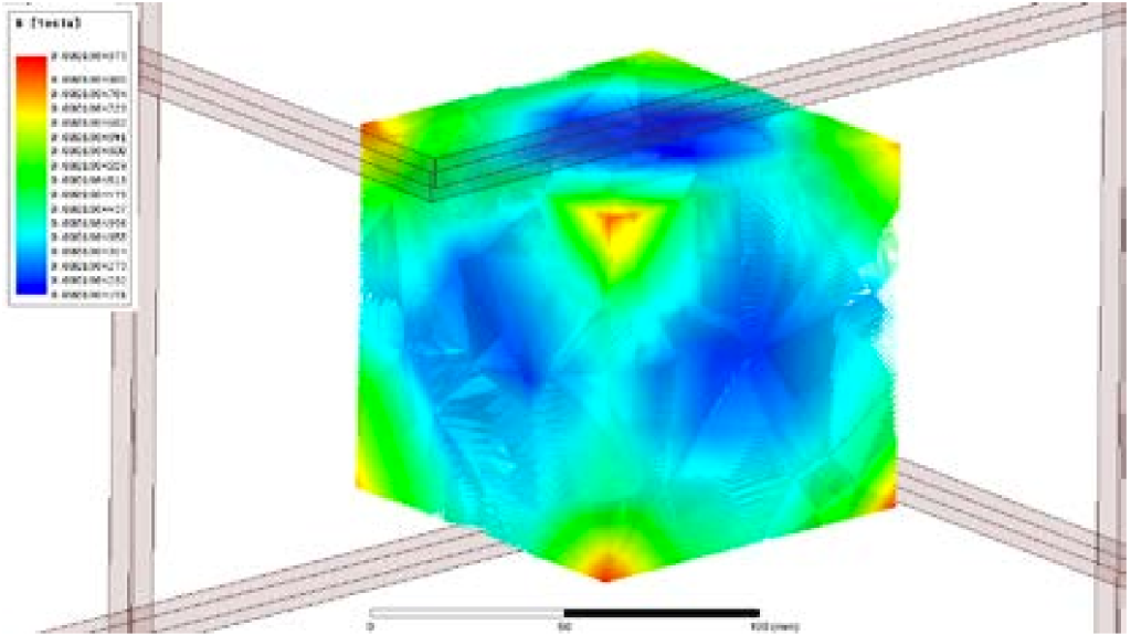
Uniformity: ±1% within 100 × 100 × 100 mm³
How we keep custom projects honest
For custom Helmholtz coil systems, we typically align on an acceptance logic early:
- Define the uniform region in a geometry you can measure (cube / cylinder / DSV-like definition depending on your test).
- Define the uniformity metric (e.g., peak-to-peak deviation, or deviation from center value) and the mapping plan.
- Provide a field-vs-current relationship (coil constant B/I) and calibration approach that matches your instrumentation.
Why work with Cryomagtech
We position Helmholtz coils as a first-class product line (not a side note). Our product pages and technical content emphasize:
- 1D / 2D / 3D configurations with closed-loop capable system integration.
- Practical lab requirements: calibration, mapping, geomagnetic compensation use cases, and engineering-driven selection.
- Matched power/control capability (bipolar constant-current supplies, optional gaussmeter-based field mode, and software control—depending on project needs).
System Options and Integration Options
A Helmholtz coil becomes a true Helmholtz Coil System when the rest of the loop is engineered: power, control, sensing, thermal stability, and safe operation.
Typical system building blocks
- Coil set: 1D / 2D / 3D, circular or square.
- Power supply: high-precision constant current source; bipolar output is commonly preferred for zero-crossing and vector synthesis use cases.
- Field measurement: optional gaussmeter / probe; used for mapping and for feedback control when stability matters.
- Control software: monitoring, logging, programmable sweeps; optional closed-loop stabilization depending on drift and environmental variation targets.
- Thermal management: air-cooled for moderate loads; water-cooled options when duty cycle and heating require it.
Magnetic field simulation and geomagnetic compensation integration
If your project is about Earth-field-related conditions, it helps to anchor the numbers:
- Earth’s field intensity is typically on the order of 25,000–65,000 nT (0.25–0.65 gauss), varying by location.
- A uniform-field system can be used to cancel or apply controlled components, and more advanced facilities use feedback magnetometers and servo loops for geomagnetic cancellation and stability.
👉Get a Quote Now – 24h Response Guaranteed
What Determines Feasibility, Cost, and Lead Time
This section exists to save you time (and prevent unrealistic RFQs).
The five variables that dominate everything
- Uniform region definition (size + geometry + “with fixture installed”)
Uniformity is only meaningful over a defined region, and real fixtures can shrink your usable uniform volume. - Uniformity target (%, ppm, or method)
Tighter uniformity generally reduces uniform volume and increases mechanical tolerance and validation effort. - Field strength and scaling
Classic Helmholtz field scales with geometry and current (B ∝ n·I / R). For larger coils (larger R), achieving higher B usually demands higher current/turns, which drives power and heating. - Duty cycle and thermal stability
Heating changes resistance and can introduce drift. If you care about stability, thermal equilibrium and monitoring become part of the system design—not an afterthought. - Waveform and frequency (DC vs AC)
Time-varying fields require driver capability matched to coil impedance; “higher frequency at high field” is where engineering tradeoffs get real.
Clear line between standard, custom, and case-by-case boundaries
Table title: What We Can Quote Fast vs What Needs Engineering Review
| Category | What it includes | What you should provide |
|---|---|---|
| Standard product range | Common 1D / 2D / 3D coil configurations, typical sizes and calibration-oriented setups | Target field range, desired uniform region size, DUT dimensions |
| Engineered-to-order | Large apertures, special frames, high-duty systems, special uniformity targets, shielding-tube fit, square cages | Uniformity definition + mapping plan + duty cycle + integration constraints |
| Case-by-case boundary | Extreme combinations (very large uniform volume + very tight uniformity + high field), or demanding AC waveforms where coil impedance dominates | Full test specification, waveform/frequency, thermal limits, acceptance criteria |
What we typically deliver for acceptance
Depending on project scope, deliverables can include:
- Coil constant (B/I) curve and verification method.
- Recommended field-mapping plan (grid / spherical sampling) and reporting format.
- System wiring and control documentation (needed for repeatable operation).
Typical Applications
Helmholtz coils are widely used wherever you need a reliable magnetic environment in an open volume—especially in low-to-moderate field regimes where uniformity dominates.
Sensor calibration and validation
- Magnetometer calibration (including triaxial calibration workflows).
- Hall probe calibration and direction-dependent characterization using 3D Helmholtz systems.
Geomagnetic compensation and magnetic environment simulation
- Earth-field cancellation / controlled low-field environments (tens of µT scale).
- Space / aerospace magnetometer test environments that require stable and controllable background-field handling (system-level approach with sensing + control loops).
EMI / magnetic interference test environments
- Magnetic-field exposure or interference simulation often focuses on low-frequency magnetic environments; engineering aligns the coil geometry, driver, and measurement plan to the intended standard or internal test method.
Research and laboratory magnetic field applications
- Controlled bias fields for materials, electronics, biomedical, and general lab experiments where access and uniformity matter.
FAQ and Request a Quote
FAQ
Do you offer a complete Helmholtz Coil System (coil + power + control), not just coils?
Yes. A typical system can include the coil set (1D/2D/3D), a constant current source, optional gaussmeter instrumentation, and PC software control (open-loop or closed-loop depending on stability targets).
Can you do 3 Axis Helmholtz Coil / Triaxial Helmholtz Coil for vector field synthesis?
Yes—3D systems are designed to generate controlled fields in X/Y/Z directions and support vector field synthesis, which is a common approach for sensor direction-dependent testing.
What does “uniform region” actually mean?
Uniformity exists only within a defined volume, and outside that region gradients increase quickly. For reliable work, define the uniform region (size/shape) and the uniformity metric, then validate with a mapping plan appropriate to your probe and fixturing.
Is circular always better than square?
Not always. Circular geometry is classic and compact; square geometry often integrates better with large DUTs and fixtures. Many large calibration cages and facilities are square for practical working space reasons.
Can you cancel the Earth’s magnetic field for sensor testing?
Yes. Earth’s field intensity is typically tens of µT (order of 25,000–65,000 nT). Cancellation and stabilization may require appropriate sensing and control strategy depending on your environment and stability target.
Do you support AC fields (time-varying magnetic fields)?
Many applications require AC or waveforms. Feasibility depends on required field amplitude vs frequency and coil/driver impedance. We evaluate this based on your waveform, frequency range, and duty cycle.
If I need very high fields, is a Helmholtz coil still the right solution?
Helmholtz coils are excellent for uniform fields and open access, but high field strength at large uniform volume can become power- and heat-intensive. If your requirement is “high field first,” alternative field sources may be more practical; we’ll recommend based on your actual uniform region and setpoints.
Inquiry guidance: what to send for a fast, accurate quotation
To quote a standard model quickly—or to evaluate a custom Helmholtz coil system—send:
- Required field range (per axis if 2D/3D) and key setpoints
- Required uniform region size and shape (cube/cylinder/DSV-like)
- Uniformity metric and acceptance method (mapping plan, probe type)
- DUT size + fixture drawing (or photo + dimensions)
- DC vs AC requirement (waveform / frequency range / duty cycle)
- Any integration constraints (shielding tube, chamber, non-magnetic materials, thermal limits)