When researchers contact magnet manufacturers, the initial request often looks something like this:
“We need a 0.5 T electromagnet.”
Unfortunately, that information alone is not enough to design or quote a real system.
Magnet performance depends on multiple parameters including geometry, uniformity requirements, thermal limits, and duty cycle. Without these details, manufacturers cannot determine whether the requested field strength is feasible or what the system configuration should be.
This article explains how to write a clear magnet specification sheet that manufacturers can realistically build.
Why a Clear Magnet Specification Matters
Magnet systems are not off-the-shelf components in many laboratory applications. They are often custom engineered systems.
Important parameters include:
- magnetic field strength
- field uniformity
- pole gap or working space
- power and thermal limits
Magnetic field generation depends strongly on geometry and current, which is why engineering specifications are required before a system can be designed.
Basic background on magnetic field generation can be found here:
https://en.wikipedia.org/wiki/Electromagnet
Providing a clear specification allows engineers to:
- determine feasibility
- estimate power requirements
- design the magnetic circuit
- propose the correct cooling solution
The Most Common Problem With Magnet Requests
Many magnet inquiries contain only partial information.
Typical missing details include:
- required uniform field volume
- available installation space
- duty cycle or operating mode
- cooling constraints
Without these parameters, the same field strength request could correspond to dramatically different system designs.
For example:
- 1 T in a 5 mm gap is relatively easy
- 1 T in a 150 mm gap may be extremely challenging
Both requests technically ask for “1 T,” but the engineering difficulty differs by orders of magnitude.
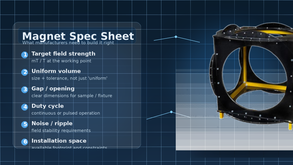
The Key Parameters in a Magnet Specification
A well-defined magnet specification sheet should include several core parameters.
These allow engineers to estimate feasibility and propose the correct configuration.
1. Target Magnetic Field Strength
The first parameter is the desired magnetic field.
This should specify:
- peak field (Tesla or mT)
- continuous field vs pulsed operation
Example:
Target field: 0.8 T continuous
2. Uniform Field Volume
Uniformity requirements strongly influence magnet geometry.
For many experiments, the sample must be placed in a region where the magnetic field varies only slightly.
Example specification:
Uniform field region:
±1% over a 20 mm cube
Helmholtz coils are often used when large uniform volumes are required.
Reference overview:
https://en.wikipedia.org/wiki/Helmholtz_coil
3. Pole Gap or Working Space
For electromagnets with pole pieces, the gap between poles determines how much space is available for the experiment.
This must include:
- sample size
- probe assemblies
- optical access
Example:
Pole gap: 80 mm
Increasing the gap significantly increases power requirements.
4. Duty Cycle and Operating Mode
Magnets used in automated experiments often operate for extended periods.
Important information includes:
- continuous operation
- pulsed operation
- ramping frequency
Example:
Duty cycle: continuous operation for several hours
This parameter affects thermal design and cooling requirements.
5. Noise and Stability Requirements
Some experiments require extremely stable magnetic fields.
Examples include:
- magnetoresistance measurements
- Hall effect experiments
- precision sensor calibration
In these cases, stability requirements may include:
- current noise limits
- field drift limits
These specifications determine the required power supply precision and control electronics.
6. Installation Space
Physical space constraints often determine the feasible magnet geometry.
Important details include:
- laboratory footprint
- height restrictions
- experimental access requirements
Example:
Maximum system width: 700 mm
Providing this information early prevents unrealistic designs.
A Practical Magnet Specification Template
Below is a simple specification format that researchers can use when requesting a custom magnet system.
Magnet Specification Template
Target field:
0.8 T continuous
Uniform region:
±1% over 20 mm cube
Pole gap / working space:
80 mm
Duty cycle:
continuous operation
Cooling preference:
water cooled
Installation constraints:
maximum system width 700 mm
Power supply interface:
analog control or computer control
Providing a structured specification significantly improves communication between researchers and magnet engineers.
From Specification to Engineering Design
Once the specification is defined, engineers can evaluate:
- magnetic circuit design
- coil geometry
- power requirements
- cooling configuration
Cryomagtech supports laboratories developing custom electromagnet and Helmholtz coil systems based on clear experimental specifications.
👉 Product Link Placeholder – Custom Electromagnet and Helmholtz Coil Systems
Providing a structured magnet specification allows manufacturers to design systems that meet both experimental and engineering requirements.
Key Takeaways
- A single field value is not enough to define a magnet system
- Uniform volume and pole gap strongly affect design feasibility
- Duty cycle and thermal limits influence cooling requirements
- Stability requirements affect power supply design
- A structured specification improves communication and reduces design errors
Clear specifications make magnet systems easier to design, quote, and deliver successfully.