Two electromagnets may have the same specifications:
- Same field strength
- Same geometry
- Same power supply
Yet in real operation:
- One runs continuously
- The other overheats within minutes
Why?
👉 The difference is often hidden inside the coil design.
This article explains how wire gauge, fill factor, and insulation class determine whether a magnet system can operate continuously—or not.
1. Duty Cycle: What It Really Means
Duty cycle defines how long a system can operate at a given load without exceeding thermal limits.
It is not just about:
- Power input
- Cooling method
It is fundamentally determined by:
👉 how heat is generated and dissipated inside the coil
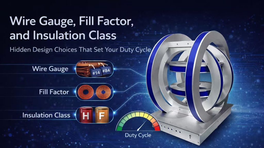
2. Wire Gauge: The Foundation of Thermal Performance
Wire gauge determines the cross-sectional area of the conductor.
Thicker Wire (Lower Gauge Number)
- Lower resistance
- Lower heat generation (I²R losses)
- Higher current capacity
Thinner Wire
- Higher resistance
- More heat at the same current
- Faster temperature rise
According to Wikipedia:
https://en.wikipedia.org/wiki/American_wire_gauge
Wire gauge directly affects electrical resistance and current-carrying capability.
Trade-Off
- Thicker wire → fewer turns possible
- Thinner wire → more turns but more heat
👉 Coil design is always a balance between field strength and thermal limits.
3. Fill Factor: How Much Copper Is Really Inside
Fill factor describes how much of the coil volume is actually conductive material.
High Fill Factor
- More copper
- Better current distribution
- Higher efficiency
Low Fill Factor
- More insulation and voids
- Reduced thermal conduction
- Lower performance under load
Reality
Fill factor is limited by:
- Insulation thickness
- Winding method
- Manufacturing tolerances
👉 A “visually full” coil is not necessarily electrically efficient.
4. Insulation Class: The True Temperature Limit
Insulation class defines the maximum allowable operating temperature.
Common classes include:
- Class B (~130°C)
- Class F (~155°C)
- Class H (~180°C)
Why It Matters
- Determines safe operating temperature
- Defines long-term reliability
- Limits allowable duty cycle
Critical Insight
👉 The conductor can survive higher temperatures
👉 The insulation usually cannot
Failure is often not copper burnout—but insulation breakdown.
5. Thermal Path: Where Heat Actually Goes
Heat generated inside the coil must be removed.
Key paths include:
- Conduction through winding layers
- Transfer to cooling channels or air
- Dissipation to surroundings
What Affects This
- Fill factor
- Material interfaces
- Coil geometry
Hidden Issue
Poor internal thermal paths lead to:
👉 hotspots inside the coil
These hotspots are:
- Invisible externally
- Responsible for premature failure
6. Why Two “Identical” Coils Behave Differently
Two coils with the same nominal specs can differ in:
- Wire gauge selection
- Packing density (fill factor)
- Insulation material
- Winding quality
Result
- Different temperature rise
- Different stability
- Different lifetime
👉 This is why datasheets rarely tell the full story.
7. Cooling Is Not a Fix for Poor Design
Many assume:
“We can just add better cooling”
But cooling does not eliminate:
- Internal resistance losses
- Poor thermal conduction paths
What Happens
- Surface temperature looks acceptable
- Internal hotspots still exist
👉 Cooling improves performance
👉 It does not replace good coil design
8. Engineering Trade-Offs in Real Systems
Designing a coil involves balancing:
- Field strength
- Current
- Temperature rise
- Physical size
Example Trade-Offs
- Higher turns → stronger field → more resistance
- Thicker wire → lower loss → larger coil size
- Higher insulation class → higher tolerance → higher cost
There is no “perfect” design—only optimized ones.
9. How Cryomagtech Designs for Reliable Duty Cycle
At Cryomagtech, duty cycle is designed from the inside out.
We consider:
- Wire gauge selection for current density
- Optimized fill factor for thermal performance
- Appropriate insulation class for long-term reliability
- Integration with cooling strategy
👉 Product link placeholder: Cryomagtech Custom Electromagnet & Coil Design Solutions
Instead of focusing only on external specifications,
we design coils that deliver:
- Stable continuous operation
- Controlled temperature rise
- Reliable long-term performance
References
- Wikipedia – American Wire Gauge
https://en.wikipedia.org/wiki/American_wire_gauge - IEEE – Thermal management in electrical windings
https://ieeexplore.ieee.org/
Key Takeaways
- Duty cycle is determined by internal coil design
- Wire gauge affects resistance and heat generation
- Fill factor defines how efficiently current is distributed
- Insulation class sets the true temperature limit
- Internal thermal paths control hotspot formation
- Cooling cannot compensate for poor design
If one magnet runs continuously and another cannot,
the answer is rarely visible from the outside—
👉 it is hidden inside the coil.