In magnetic field measurements, users often focus on:
- field strength
- power supply stability
- sensor accuracy
But in many real experiments, the largest source of error is much simpler:
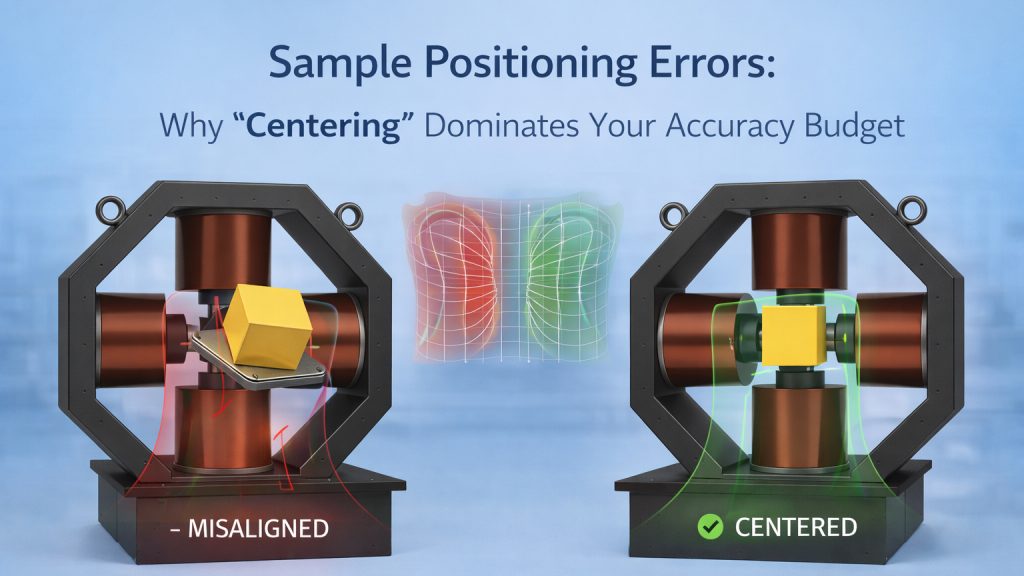
👉 The sample is not positioned correctly
Even small positioning errors can dominate the entire accuracy budget—especially in systems designed for field uniformity.
1. The Myth of “Uniform Field Everywhere”
Helmholtz coils and electromagnets are often described as producing a “uniform field”.
In reality:
👉 Uniformity exists only within a limited volume
Outside this region:
- field gradients increase
- measurement error rises rapidly
According to Wikipedia, Helmholtz coils provide a highly uniform field only near the geometric center.
2. What “Centering” Really Means
Centering is not just placing the sample “roughly in the middle”.
It involves:
- alignment along all three axes (X, Y, Z)
- correct orientation relative to field direction
- consistent positioning across repeated measurements
👉 A 2–3 mm offset can already exceed your expected accuracy tolerance.
3. Uniform Volume Boundaries: The Invisible Limit
Every system has a defined uniform region, often specified as:
- ±1% uniformity within a sphere or cube
- e.g., 20 mm diameter region
What Happens Outside
- field deviation increases non-linearly
- calibration assumptions break down
👉 If your sample extends beyond this region, your data is already compromised.
4. Common Positioning Errors (That Look Like “System Problems”)
Off-Center Placement
- Causes systematic field error
- Often mistaken for calibration drift
Tilted Samples
- Changes effective field component
- Affects vector measurements
Inconsistent Repositioning
- Leads to poor repeatability
- Creates “random” measurement variation
Fixture-Induced Offset
- Improvised holders introduce bias
- Especially common in optical setups
5. Why Positioning Errors Dominate the Accuracy Budget
Let’s be blunt:
- Power supply stability: ppm level
- Sensor accuracy: calibrated
- Positioning error: millimeters
👉 Guess which one dominates?
In precision setups, geometry errors often exceed electrical errors.
6. Practical Centering Methods That Actually Work
Mechanical Alignment
- Use fixed reference points
- Define a repeatable origin
Positioning Fixtures
- Custom holders
- Non-magnetic materials
- Defined insertion depth
Symmetry Checks
- Measure at mirrored positions
- Compare results
Field Mapping (Basic Version)
- Move probe slightly around center
- Identify maximum uniform region
7. Repeatability: The Real Benchmark
Accuracy is meaningless without repeatability.
A good setup should:
- return the same result after repositioning
- minimize operator-dependent variation
👉 If results change every time you reinstall the sample, positioning is the issue.
8. Designing for Positioning, Not Just Field
A well-designed system considers:
- mechanical guides
- alignment markers
- fixture compatibility
- optical and probe access
According to IEEE engineering practices, mechanical repeatability is critical for reliable electromagnetic measurements.
9. How Cryomagtech Supports Accurate Positioning
Cryomagtech systems are designed not only for field performance, but also for repeatable positioning, including:
- defined uniform regions
- fixture-compatible structures
- guidance for sample alignment
- integration with experimental setups
👉 Product link placeholder: Cryomagtech Electromagnet & Positioning Solutions
Because accurate measurements depend as much on positioning as on the magnet itself.
References
- Wikipedia – Helmholtz coil field uniformity
https://en.wikipedia.org/wiki/Helmholtz_coil - IEEE – Measurement repeatability and system design
https://ieeexplore.ieee.org/
Key Takeaways
- Magnetic field uniformity exists only within a limited region
- Small positioning errors can dominate measurement accuracy
- Off-center placement and tilt are common hidden issues
- Repeatability is the key indicator of correct positioning
- Proper fixtures and alignment methods significantly improve results
- System design should include positioning considerations