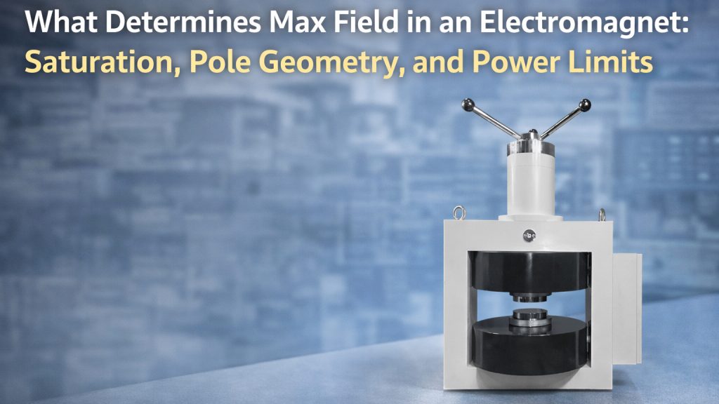
When specifying an electromagnet, one of the most common questions is:
“What is the maximum magnetic field this system can generate?”
At first glance, this seems straightforward. However, in real systems, the maximum achievable field is determined by multiple interacting factors, including:
- magnetic saturation
- pole geometry
- air gap size
- coil heating
- power supply capability
This article explains what actually limits the maximum field in an electromagnet and why achieving higher fields becomes increasingly difficult.
The Ideal vs Real Electromagnet
In theory, the magnetic field generated by a coil increases with current:
B ∝ I
However, real electromagnets include:
- ferromagnetic cores
- air gaps
- thermal constraints
These factors introduce practical limits that prevent unlimited field scaling.
Background on electromagnets:
https://en.wikipedia.org/wiki/Electromagnet
1. Magnetic Saturation: The Fundamental Limit
The most important limitation is magnetic saturation.
Ferromagnetic materials (such as iron) can only support magnetic flux up to a certain level.
Beyond this point:
- increasing current produces diminishing increases in field
- efficiency drops sharply
Background reference:
https://en.wikipedia.org/wiki/Magnetic_saturation
Typical saturation levels:
- ~1.5–2.2 Tesla for common magnetic materials
This means:
No matter how much current you add, the core cannot produce unlimited field.
2. Pole Geometry and Magnetic Flux Distribution
The geometry of the magnet poles strongly affects field strength.
Important parameters include:
- pole face area
- pole shape
- magnetic circuit design
Smaller Pole Area → Higher Field
Reducing pole area concentrates magnetic flux, increasing field strength.
But this comes with trade-offs:
- reduced uniform region
- increased field gradients
Pole Shape and Uniformity
Flat poles, tapered poles, or shaped pole caps affect:
- field uniformity
- fringe fields
- usable measurement volume
Designing pole geometry is a balance between:
- maximum field
- uniformity
- accessibility
3. Air Gap: The Most Expensive Parameter
The air gap between poles is one of the most critical factors.
Magnetic field strength decreases rapidly as gap size increases.
In simplified terms:
- larger gap → higher reluctance → lower field
To maintain the same field in a larger gap, the system must:
- increase current
- increase coil turns
- increase power
This is why:
A small gap high-field magnet is relatively easy,
but a large gap high-field magnet becomes extremely challenging.
4. Coil Heating and Thermal Limits
Electrical current in the coil produces heat:
As current increases:
- temperature rises
- resistance increases
- cooling requirements become critical
Without proper cooling:
- insulation may degrade
- coil lifetime decreases
- field stability is affected
Water-cooled systems are often required for high-field operation.
5. Power Supply Capability
Even if the magnet can theoretically reach a certain field, the power supply must support it.
Key constraints include:
Current Capacity
Higher fields require higher current.
Voltage (Compliance Voltage)
To drive current through inductive coils:
Insufficient voltage limits:
- ramp speed
- achievable current
Stability and Noise
High field experiments often require:
- stable current output
- low noise
This becomes more difficult at higher power levels.
6. The Interdependence of All Factors
These limitations are not independent.
For example:
- increasing gap → requires more current
- more current → increases heating
- increased heating → requires better cooling
- better cooling → increases system complexity
As a result:
Maximum field is not a single parameter—it is the outcome of a complete system design.
7. Practical Design Trade-Offs
In real applications, engineers must balance:
- maximum field strength
- uniform field region
- system size
- thermal stability
- cost
Typical strategies include:
- optimizing pole geometry
- selecting appropriate core materials
- using water cooling
- matching power supply capability
8. System-Level Design Approach
Achieving high magnetic fields requires coordinated design of:
- magnetic circuit
- coil system
- cooling system
- power supply
Cryomagtech provides electromagnet systems designed with these constraints in mind, helping researchers balance field strength, stability, and system feasibility.
👉 Product Link Placeholder – High-Field Electromagnet Systems
System-level optimization ensures that the requested magnetic field can be achieved reliably.
Key Takeaways
- Magnetic saturation sets a fundamental limit on field strength
- Pole geometry affects both field strength and uniformity
- Air gap size has a major impact on achievable field
- Coil heating limits current and continuous operation
- Power supply capability constrains real-world performance
Maximum magnetic field is not just a number—it is the result of multiple engineering trade-offs.