Designing a calibration rig for magnetometers or IMUs is not about generating a magnetic field.
It is about controlling geometry, alignment, and repeatability well enough that your error model actually means something.
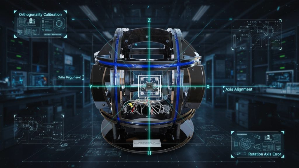
This article focuses on the practical engineering issues calibration labs face every day: orthogonality, center offset, rotation axis error, and fixture material selection.
It is written for teams building or upgrading 3-axis coil calibration setups, not for textbooks.
1. Why Calibration Accuracy Is a Mechanical Problem First
Most magnetometer and IMU calibration errors are blamed on sensors or algorithms.
In practice, the dominant contributors are often:
- Coil axis misalignment
- Sample not located at the magnetic center
- Rotational axis not coincident with field center
- Fixtures introducing parasitic magnetic effects
If the geometry is wrong, no amount of post-processing will save you.
2. Orthogonality: When “3-Axis” Is Not Really Orthogonal
What Orthogonality Means in Practice
In an ideal 3-axis coil system:
- X, Y, Z field vectors are mutually perpendicular
- Field magnitude along each axis is independent
In real systems, small angular errors (even <0.1°) cause:
- Cross-axis coupling
- Elliptical instead of circular field rotation
- Bias in scale factor calibration
Engineering Reality
Orthogonality errors typically come from:
- Coil frame machining tolerances
- Assembly stack-up errors
- Deformation under thermal load
For high-accuracy calibration, mechanical orthogonality must be characterized and included in the error model, not assumed.
3. Center Offset: The Silent Calibration Killer
Why Centering Matters
3-axis coil systems are designed to generate a uniform field only within a defined central volume.
If the sensor is offset from this region:
- Field gradients introduce scale errors
- Rotational calibration becomes asymmetric
- Results vary with rotation angle
Practical Guidelines
- Define the magnetic center using mapping or reference probes
- Design fixtures that constrain sensor position repeatably
- Avoid “hand-placed” samples for precision calibration
Even a few millimeters of offset can dominate your uncertainty budget.
4. Rotation Axis Error: Where Mechanics Meets Math
Common Assumption
Many calibration rigs assume:
“The sensor rotates about its own center.”
This is often false.
Typical Error Sources
- Rotation axis offset from magnetic center
- Axis tilt relative to gravity or coil axes
- Bearing runout and wobble
These errors manifest as:
- Apparent non-linearity
- Angle-dependent bias
- Misidentified soft-iron effects
A good calibration rig treats rotation as a measurable parameter, not a perfect abstraction.
5. Fixture Material Selection: What You Mount Matters
Non-Magnetic Does Not Mean Non-Problematic
Common fixture materials include:
- Aluminum
- Brass
- Plastics (PEEK, Delrin, ABS)
But even “non-magnetic” materials can cause issues through:
- Eddy currents (in AC or rotating fields)
- Thermal expansion shifting alignment
- Mechanical creep over time
Best Practices
- Minimize conductive loops near the sensor
- Prefer mechanically stiff, low-expansion materials
- Keep fixtures modular for recalibration and replacement
Fixtures should be treated as part of the calibration system, not accessories.
6. Linking Hardware Errors to Software Error Terms
A robust calibration workflow explicitly links:
| Physical Source | Software Error Term |
|---|---|
| Coil non-orthogonality | Cross-axis sensitivity |
| Center offset | Gradient-induced bias |
| Rotation axis tilt | Angle-dependent residuals |
| Fixture deformation | Time drift / hysteresis |
Ignoring this mapping leads to unstable or non-transferable calibration results.
7. Building a Practical 3-Axis Calibration Platform
Cryomagtech supports calibration laboratories with integrated solutions combining:
- 3-axis Helmholtz coil systems
- Mechanical alignment-friendly frames
- Calibration-ready fixture concepts
- Software-aware system design
👉 Product link placeholder: Cryomagtech 3-Axis Coil Calibration Systems & Fixtures
The goal is not just to generate a field, but to control geometry well enough that calibration results are defensible.
References
- Wikipedia – Helmholtz Coil
https://en.wikipedia.org/wiki/Helmholtz_coil - IEEE – Calibration and error modeling of triaxial magnetic sensors
https://ieeexplore.ieee.org/
Key Takeaways
- Calibration accuracy is limited by mechanical alignment first
- Orthogonality and centering errors dominate real systems
- Rotation axis errors must be modeled, not ignored
- Fixture design directly affects calibration repeatability
A calibration rig is a measurement instrument, not just a magnet plus a turntable.