
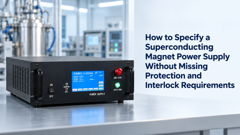
When purchasing a superconducting magnet power supply, many users initially focus on only a few specifications:
- Maximum current
- Maximum voltage
- Current stability
- Output accuracy
- Communication interface
- Ramp rate
These parameters are important.
However, for superconducting magnets, a power supply is not simply a high-precision DC current source.
It is part of a complete magnet operating system that must safely manage:
- Stored magnetic energy
- Ramp-up and ramp-down processes
- Quench events
- Cryogenic conditions
- Fault detection
- Operator safety
- Communication with external control systems
A power supply that matches the current and voltage requirements but lacks appropriate protection and interlock design may not be suitable for the actual superconducting magnet.
The correct specification process should therefore start from the magnet operating requirements, not only the electrical output numbers.
1. Why Superconducting Magnet Power Supply Selection Is Different
A conventional electromagnet can usually tolerate relatively simple current control.
A superconducting magnet is different.
Once energized, the magnet stores energy in its inductive circuit.
The relationship is:
E = 1/2 × L × I²
where:
- E = stored magnetic energy
- L = magnet inductance
- I = operating current
Even a laboratory superconducting magnet can store significant energy.
This means that changing current too quickly, losing superconductivity, or operating outside safe conditions can create risks including:
- Excessive voltage
- Local heating
- Coil damage
- Quench events
- Cryogenic disturbance
IEEE technical discussions on superconducting magnet systems emphasize that superconducting magnet assemblies involve not only the coil itself but also cryogenic systems, current supply interfaces, and protection considerations. IEEE Technology Navigator
Therefore, the power supply should be viewed as a magnet control and protection platform, not only a current source.
2. Start With the Magnet Electrical Parameters
Before requesting a quotation, the most important information is the superconducting magnet specification.
A supplier needs to understand the actual magnet load.
Essential Magnet Data
Provide:
- Maximum operating current
- Maximum charging current
- Operating voltage range
- Coil resistance
- Magnet inductance
- Stored energy
- Persistent-mode or driven-mode operation
- Current polarity requirements
- Ramp-up rate
- Ramp-down rate
- Required field stability
Without this information, a supplier cannot properly determine:
- Power supply capacity
- Ramp control strategy
- Protection requirements
- Discharge method
- Interlock logic
Current Alone Is Not Enough
A common mistake is saying:
“The magnet requires 100 A.”
This is incomplete.
Two 100 A superconducting magnets may require completely different power supplies.
Example:
Magnet A
- 100 A
- 0.1 H inductance
Magnet B
- 100 A
- 5 H inductance
The current rating is identical.
But the stored energy, ramp behavior, and protection requirements are completely different.
3. Understand the Role of Ramp Rate
Ramping is one of the most important specifications for superconducting magnet power supplies.
A superconducting magnet cannot always be charged instantly.
The current change:
dI/dt
creates effects including:
- Induced voltage
- Eddy current heating
- Mechanical stress
- AC losses
- Potential quench risk
A superconducting magnet power supply therefore needs controlled ramping.
Typical Ramp Functions Include
- Adjustable ramp-up rate
- Adjustable ramp-down rate
- Ramp pause
- Soft start
- Emergency fast discharge
- Programmable current profiles
For laboratory magnets, the user may require different ramp rates for:
- Initial magnet charging
- Field scanning
- Fine field adjustment
- Safe discharge
A good power supply allows these parameters to be controlled rather than fixed.
4. Ramp Rate Is a Balance Between Speed and Safety
A faster ramp is not always better.
Increasing ramp speed may improve experiment efficiency.
However, it can also increase:
- Eddy current losses
- Thermal load
- Mechanical stress
- Field instability
For superconducting magnets, the optimum ramp rate depends on:
- Magnet construction
- Superconductor type
- Cryogenic margin
- Magnet inductance
- Experimental requirement
For example:
A high-field research magnet may prioritize stability over fast charging.
A pulsed or scanning application may prioritize faster field changes.
The power supply should therefore provide enough flexibility rather than simply the highest possible ramp rate.
5. Current Stability and Regulation Requirements
After reaching the target current, the power supply must maintain stable operation.
Important parameters include:
- Current accuracy
- Current ripple
- Long-term drift
- Noise level
- Regulation method
The required stability depends strongly on the application.
Typical Applications With Higher Stability Requirements
- NMR-related systems
- Precision magnetic measurements
- Quantum material research
- Magnetic resonance experiments
- Long-duration transport measurements
Applications With Lower Stability Requirements
- Magnet testing
- Basic field generation
- Educational demonstrations
A common mistake is purchasing extremely high current accuracy while ignoring other system limitations.
The actual magnetic field stability also depends on:
- Magnet design
- Persistent-mode operation
- Temperature stability
- Mechanical stability
- Field measurement method
6. Four-Quadrant Operation: Is It Really Needed?
Another important specification is current polarity.
Some users only need:
0 A → +Imax
Others need:
−Imax → 0 → +Imax
This determines whether a four-quadrant power supply is required.
One-Quadrant Operation
Suitable for:
- Single-direction magnetic fields
- Simple charging applications
- Persistent-mode magnets
Four-Quadrant Operation
Useful for:
- Bipolar field sweeps
- Magnetic hysteresis measurements
- Reversible field applications
- Research requiring field polarity changes
A superconducting magnet power supply should not include four-quadrant capability automatically unless the experiment requires it.
It adds complexity and cost.
7. Protection Is Not an Optional Feature
The protection system is one of the biggest differences between a normal DC supply and a superconducting magnet power supply.
The reason is simple:
A superconducting magnet can suddenly become resistive.
This event is called a quench.
What Happens During a Quench?
A small region of the superconducting coil loses superconductivity.
The current then begins flowing through resistive material.
This creates:
- Local heating
- Voltage generation
- Energy dissipation
If not controlled, the stored magnetic energy can damage the magnet.
Wikipedia’s overview of superconducting magnets describes quench events as a transition from superconducting to resistive operation, requiring protection systems to limit damage from stored magnetic energy and voltage effects. Wikipedia
8. Common Protection Functions to Specify
A professional superconducting magnet power supply specification should clearly define protection functions.
Overcurrent Protection
Prevents:
- Excessive magnet current
- Operator mistakes
- Control-system failures
Specify:
- Trip threshold
- Response time
- Reset method
Overvoltage Protection
Important during:
- Rapid current changes
- Fault conditions
- Magnet discharge
Specify:
- Maximum allowed output voltage
- Protection response
Overtemperature Protection
Relevant for:
- Power electronics
- Current leads
- Cooling systems
Short-Circuit Protection
Protects:
- Power supply output stage
- Cabling
- Magnet circuit
Quench Protection Interface
For advanced systems, the power supply should communicate with:
- Quench detection system
- Energy extraction circuit
- Magnet protection controller
9. Interlocks: The Safety Communication Between Systems
Interlocks are often overlooked during early specification discussions.
However, they are essential in a superconducting magnet system.
An interlock allows one subsystem to prevent unsafe operation of another.
Typical Interlock Signals Include
Cryogenic Interlocks
Examples:
- Cryostat temperature too high
- Cooling failure
- Low helium level
- Compressor fault
Action:
Prevent magnet energization or initiate shutdown.
Magnet Protection Interlocks
Examples:
- Quench detected
- Voltage imbalance
- Abnormal resistance
Action:
Immediately stop charging and activate protection.
External Safety Interlocks
Examples:
- Emergency stop
- Door switch
- Laboratory safety system
Action:
Disable output.
Research systems such as superconducting magnet power supplies often integrate ramping operation with interlock signals from protection systems to ensure safe operation. Chinese Particle Physics Center
10. Define the Interlock Logic Clearly
Simply saying:
“The power supply needs interlock.”
is not enough.
A supplier should understand:
What Happens When the Signal Is Triggered?
Possible actions:
- Stop ramping
- Hold current
- Ramp down safely
- Immediately disable output
- Activate energy dump
What Type of Signal?
Examples:
- Dry contact
- TTL
- Analog signal
- Digital communication
- Ethernet command
Who Controls the Decision?
Possible architecture:
Cryogenic controller → Magnet protection system → Power supply
or:
PLC / Lab control system → Power supply
The control hierarchy should be defined before integration.
11. Communication Interfaces: More Than Just Remote ON/OFF
Modern superconducting magnet systems are often integrated into laboratory automation.
Therefore, communication requirements matter.
Common Interfaces
- RS-232
- RS-485
- USB
- Ethernet
- TCP/IP
- Analog control
- Digital I/O
Typical Remote Commands
A laboratory may require:
- Set current
- Read current
- Start ramp
- Stop ramp
- Pause ramp
- Read status
- Read fault information
- Record operating history
Communication Should Include Status Information
A useful interface should not only accept commands.
It should report:
- Actual current
- Voltage
- Ramp state
- Fault state
- Interlock state
- Protection status
This is especially important for unattended operation.
12. Persistent Mode Changes the Power Supply Requirement
Some superconducting magnets operate in persistent mode.
In this condition:
- The magnet is charged to the target current.
- A superconducting switch closes.
- The external power supply can be disconnected.
The magnet current then circulates in a closed superconducting loop.
Persistent operation can provide excellent field stability because the field no longer depends directly on the power supply output.
Wikipedia explains that many superconducting magnets use persistent switches to create a closed superconducting loop after charging, allowing the power supply to be disconnected while maintaining the magnetic field. Wikipedia
Questions to Ask
- Is persistent mode required?
- Does the magnet have a persistent switch?
- Is heater control required?
- Is a switch heater supply included?
- Is current decay monitoring needed?
These details significantly affect system configuration.
13. Energy Extraction and Fast Discharge Requirements
Large-inductance superconducting magnets may require controlled energy discharge.
A simple current ramp-down may be too slow.
A protection system may need:
- Dump resistor
- Energy extraction circuit
- Fast discharge path
- Controlled voltage limitation
American Magnetics notes that superconducting magnet power supply systems may include programmable charge rates, current limits, voltage limits, and fast ramp-down options for magnets with significant stored energy. American Magnetics
The correct discharge method depends on:
- Magnet inductance
- Stored energy
- Maximum acceptable voltage
- Protection strategy
14. Common Specification Mistakes
Mistake 1: Only Providing Current Rating
Wrong:
Need 50 A power supply.
Better:
Magnet requires 50 A maximum current, 20 V maximum voltage, inductance X H, ramp rate X A/min, stability X ppm.
Mistake 2: Ignoring Quench Protection
Wrong:
We only need stable current output.
Better:
Define quench detection, protection response, and shutdown logic.
Mistake 3: Asking for Communication Without Defining Functions
Wrong:
Ethernet required.
Better:
Ethernet communication required for setting current, monitoring status, reading alarms, and integrating with laboratory control software.
Mistake 4: Ignoring Future Expansion
Wrong:
Select the minimum supply for today’s experiment.
Better:
Consider future magnet upgrades, higher current requirements, and automation integration.
15. A Practical Specification Checklist
Before requesting a quotation, prepare the following information.
Magnet Parameters
- Magnet type
- Manufacturer
- Maximum current
- Maximum voltage
- Inductance
- Stored energy
- Persistent mode capability
Operation Requirements
- Ramp-up rate
- Ramp-down rate
- Current stability
- Current accuracy
- Field stability requirement
- Bipolar operation requirement
Protection Requirements
- Overcurrent protection
- Overvoltage protection
- Quench detection interface
- Energy extraction requirement
- Emergency shutdown
Interlock Requirements
- Cryogenic interlock
- Magnet protection interlock
- External safety interlock
- PLC integration
Communication Requirements
- Interface type
- Control commands
- Monitoring parameters
- Data logging requirements
Providing these details significantly improves quotation accuracy.
16. How Cryomagtech Approaches Superconducting Magnet Power Supply Configuration
Cryomagtech provides superconducting magnet power supply solutions designed around the complete magnet operating requirement rather than only output current.
Configuration considerations include:
- Magnet current and voltage matching
- Programmable ramp control
- Current stability
- Protection functions
- Interlock integration
- Remote communication
- Laboratory automation compatibility
- Custom magnet integration
👉 Product link placeholder: Cryomagtech Superconducting Magnet Power Supply Solutions
The goal is to ensure that the power supply, superconducting magnet, protection system, and control architecture operate as one complete system.
A successful superconducting magnet project is not only about reaching the target current.
It is about reaching that current safely, repeatedly, and controllably.
17. Key Takeaways
- A superconducting magnet power supply is more than a high-current DC source.
- Magnet inductance and stored energy determine ramping and protection requirements.
- Ramp rate should balance experimental speed and magnet safety.
- Protection functions such as overcurrent, overvoltage, and quench response are essential.
- Interlocks connect the power supply with cryogenic and magnet protection systems.
- Communication requirements should define commands, monitoring, and status feedback.
- Persistent-mode magnets require additional considerations such as persistent switches and heater control.
- Future expansion should be considered before selecting the power supply rating.
- A complete specification must include magnet parameters, operation requirements, protection, interlocks, and communication.
When specifying a superconducting magnet power supply, the most important question is not:
“Can this supply provide enough current?”
It is:
“Can this supply safely control, protect, and communicate with our superconducting magnet throughout its entire operating cycle?”
References
IEEE – Superconducting Magnet Systems
IEEE provides technical information on superconducting magnet assemblies, including superconducting coils, cryogenic systems, and current supply interfaces. IEEE Technology Navigator
Source:
https://technav.ieee.org/topic/superconducting-magnets/
IEEE – Superconducting Magnet Power Supply and Hard-Wired Protection
This IEEE paper discusses testing and modification of superconducting magnet power supply systems and quench protection requirements. IEEE Xplore
Source:
https://ieeexplore.ieee.org/ielaam/77/8048707/8059829-aam.pdf