
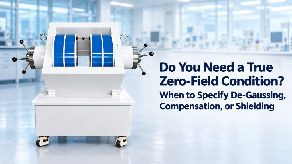
“Zero magnetic field” sounds like a simple specification.
In practice, it is one of the most easily misunderstood requirements in low-field Hall measurements, magnetic sensor calibration, magnetometry, and magnetic-sensitive experiments.
A customer may say:
“We need zero field before the measurement starts.”
But that could mean very different things:
- Reduce the remanent field of an electromagnet after a high-field sweep
- Cancel the Earth’s magnetic field around the sample
- Stabilize the field against elevators, motors, vehicles, or power-line disturbances
- Create a low-field volume for sensor calibration
- Reduce the field inside a shield to the nT range
- Return repeatedly to a reproducible magnetic baseline between measurements
These are not the same engineering problem.
And they should not automatically lead to the same solution.
Depending on the experiment, the correct approach may be degaussing, active magnetic field compensation, passive magnetic shielding, or a combination of all three.
The first step is therefore not choosing hardware.
It is defining what “zero field” actually means for your experiment.
1. There Is Almost No Such Thing as a Practical “Absolute Zero Field”
In laboratory specifications, “zero field” should usually be understood as:
A residual magnetic field below a defined acceptable limit within a defined measurement region and time period.
That is very different from literally demanding:
B = 0 T
A useful zero-field specification therefore needs numbers.
Instead of Saying
“We need zero magnetic field.”
Specify
- Residual field: <10 µT, <1 µT, <100 nT, etc.
- Measurement volume: one point, 10 × 10 × 10 mm³, 100 × 100 × 100 mm³, etc.
- Number of controlled axes: 1D or 3D
- Stability over time
- Allowed field gradient
- Frequency range of disturbances that must be suppressed
- Whether the requirement applies only before measurement or continuously during measurement
Without these definitions, two suppliers can quote completely different systems while both claiming to provide a “zero-field solution.”
2. Why the Earth’s Magnetic Field Already Matters
A laboratory without any magnet turned on is not a zero-field environment.
The Earth itself provides a substantial magnetic background.
NOAA reports that the total geomagnetic field is roughly 25,000–65,000 nT, equivalent to approximately 25–65 µT or 0.25–0.65 G, depending on geographic location. NCEI
For a 1 T electromagnet experiment, this may be negligible.
For an experiment targeting:
- 100 µT
- 50 µT
- 10 µT
- 1 µT
it may dominate the measurement.
And the laboratory field is not simply the Earth’s field.
Other Sources Can Include
- Steel building structures
- Elevators
- HVAC equipment
- Nearby magnets
- Electric motors
- Power supplies
- AC power lines
- Vehicles
- Laboratory furniture containing ferromagnetic material
This is why “turning the electromagnet current to zero” does not mean that the sample sees zero magnetic field.
3. Before Choosing a Solution, Identify Which “Zero-Field Problem” You Actually Have
There are three major problems that are frequently mixed together.
Problem A — The Magnet Retains Field After Current Returns to Zero
This is primarily a remanence and hysteresis problem.
Typical solution:
Degaussing / demagnetization
Problem B — The Laboratory Has an Ambient Magnetic Field
This is primarily an environmental field cancellation problem.
Typical solution:
Active magnetic field compensation
Problem C — External Magnetic Disturbances Must Be Strongly Attenuated
This is primarily an isolation problem.
Typical solution:
Passive magnetic shielding
In very demanding ultra-low-field experiments, these methods may be combined rather than selected individually.
A recent review of magnetic shielding technology similarly treats shielding materials, magnetization control such as degaussing, and active compensation as distinct but complementary approaches to creating ultra-low-field environments. PubMed Central (PMC)
4. What Degaussing Actually Solves
Consider a conventional electromagnet with an iron yoke.
You increase the magnetic field to a high positive value and then reduce the power-supply current back to:
0 A
You might expect:
0 A → 0 T
But a ferromagnetic magnetic circuit has hysteresis.
The iron can retain magnetization after excitation is removed, producing a residual magnetic field in the pole gap.
Degaussing Targets This Residual Magnetization
A degaussing sequence generally applies progressively decreasing magnetic excitation with alternating polarity.
The objective is to reduce the remanent magnetization state of the magnetic circuit and therefore reduce the residual field.
Conceptually:
Large positive field → negative field → smaller positive field → smaller negative field → … → near zero
The exact sequence depends on the magnet, power supply, magnetic circuit, and required residual-field performance.
Degaussing Is Useful When
- An electromagnet has just operated at relatively high field
- The experiment needs a reproducible low-field starting condition
- Hysteresis affects low-field sweeps
- Small coercive fields need to be measured
- Hall or magnetoresistance measurements pass through zero field
- A calibration procedure requires repeatable approach to zero
But there is a critical limitation.
Degaussing the electromagnet does not remove the Earth’s magnetic field.
It also does not continuously suppress external magnetic disturbances.
5. Degaussing a Magnet and Degaussing a Magnetic Shield Are Related—but Not Identical Tasks
The term “degaussing” can also refer to magnetic shielding.
High-permeability shielding materials can develop their own magnetic history and remanence.
For very low-field environments, magnetic shields may therefore need a controlled degaussing or magnetic equilibration process to minimize residual magnetization.
Research on magnetically shielded rooms shows that degaussing can substantially reduce the residual field inside a shielded volume. One published study describes a magnetically shielded room using dedicated degaussing coils to reach the low-nT residual-field regime required for sensitive measurements. PubMed Central (PMC)
The engineering objective is similar:
reduce unwanted remanent magnetization.
But the hardware scale, coil arrangement, acceptance criteria, and operating procedure can be very different from degaussing an electromagnet.
6. What Active Magnetic Compensation Solves
Now imagine that your electromagnet has been successfully degaussed.
Its residual field is very small.
You measure the sample again.
The field still reads:
+42 µT
Nothing is necessarily wrong with the electromagnet.
You may simply be measuring the ambient geomagnetic field.
This is where active magnetic field compensation becomes relevant.
Basic Active Compensation Architecture
A typical system uses:
- Magnetic field sensor
- One-axis or three-axis compensation coils
- Precision current sources
- Control electronics
- Calibration software
- Optional closed-loop feedback
The system generates a magnetic field that opposes the unwanted background field.
For example:
Ambient X field: +28 µT
Compensation coil: −28 µT
Ideal resulting field:
≈0 µT along X
In a three-axis system, the same principle can be applied independently to:
- X
- Y
- Z
This is why 3-axis Helmholtz or vector-coil systems are particularly useful for low-field control.
7. Why Three-Axis Compensation Often Matters
The Earth’s magnetic field is a vector.
Reducing only one component does not create a true low-field vector environment.
Suppose:
- Bx = +30 µT
- By = +10 µT
- Bz = −35 µT
Cancelling Bx alone still leaves substantial residual field in the other directions.
For applications such as:
- Magnetometer calibration
- IMU and compass testing
- Low-field Hall experiments
- Direction-sensitive magnetic sensors
- Weak-field materials research
a three-axis system allows independent adjustment of the complete magnetic-field vector.
Cryomagtech’s Helmholtz coil platforms include 1D, 2D, and 3D configurations intended for controlled field generation, calibration, and applications including geomagnetic compensation. Cryomagtech
8. Open-Loop Compensation vs Closed-Loop Compensation
Not every compensation system needs continuous feedback.
Open-Loop Compensation
The ambient field is measured first.
Fixed current values are then applied to the compensation coils.
This can work well when:
- The laboratory environment is relatively stable
- Measurements are short
- Required accuracy is moderate
- The main objective is cancelling the static geomagnetic offset
It is comparatively simple.
But if the ambient field changes, the compensation current does not automatically change with it.
Closed-Loop Compensation
A field sensor continuously measures the magnetic environment.
The control system continuously adjusts coil current to reduce the residual error.
This is more suitable when:
- Experiments run for long periods
- Environmental field drift matters
- Nearby equipment switches on and off
- Very stable low-field conditions are required
- Repeatability between measurements is important
Recent literature on active magnetic compensation describes the system in terms of compensation coils, magnetic sensing, and feedback/control strategies for suppressing environmental magnetic disturbances. ScienceDirect
9. Active Compensation Is Not the Same as Magnetic Shielding
These two terms are often used interchangeably.
They should not be.
Active Compensation
It generates another magnetic field to cancel an unwanted field.
Conceptually:
Bcompensation ≈ −Bambient
Passive Magnetic Shielding
It uses magnetic materials and structural geometry to reduce the field reaching the protected volume.
The shield does not continuously generate an opposing correction field.
These approaches solve different parts of the problem.
10. When Magnetic Shielding Becomes Necessary
For many ordinary Hall measurements or sensor calibration systems, active compensation can provide a practical low-field environment without constructing a complete shielding enclosure.
But as the required residual field becomes extremely small, external interference becomes increasingly important.
Passive magnetic shielding may be required when:
- Residual field requirements enter the nT range
- Very weak magnetic signals must be measured
- Environmental field fluctuations exceed the experiment tolerance
- High-sensitivity magnetometers are used
- Nearby disturbances cannot realistically be removed
- The experiment requires strong isolation from the surrounding magnetic environment
High-permeability magnetic materials can redirect magnetic flux away from the protected region, reducing the external field inside the enclosure.
Modern ultra-low-field laboratories often combine multiple shielding layers, degaussing, and active compensation rather than relying on one technique alone. PubMed Central (PMC)
11. Why Shielding Alone May Still Not Give You “Zero”
This is another common misunderstanding.
A magnetic shield has a shielding factor.
It does not magically convert:
50 µT → exactly 0 T
Residual magnetic fields can remain because of:
- Shield material magnetization
- Openings and penetrations
- Structural asymmetry
- Environmental field penetration
- Mechanical stress
- Internal magnetic components
- Spatial field gradients
The shielding material itself may also require degaussing.
And if the remaining field must be adjusted precisely, active coils may still be installed inside or around the shield.
This leads to an important system concept:
Shielding reduces the problem.
Degaussing controls remanence.
Active compensation corrects what remains.
12. A High-Performance Zero-Field System May Use All Three
For an ultra-sensitive experiment, the architecture might look like this:
Stage 1 — Passive Shielding
Reduce the external magnetic environment substantially.
Stage 2 — Degaussing
Reduce residual magnetization in the shielding structure.
Stage 3 — Active 3-Axis Compensation
Measure and correct the remaining field.
Stage 4 — Closed-Loop Stabilization
Maintain the required field during the experiment.
This type of combined architecture is relevant to demanding applications such as quantum sensing and ultra-sensitive magnetic measurements.
But it would usually be excessive for a conventional Hall system that only needs a repeatable field near zero.
That difference can represent a very large difference in project cost and complexity.
13. Low-Field Hall Measurements: Do You Really Need “True Zero”?
Hall measurement is a good example of why this specification needs careful definition.
Suppose a Hall system sweeps:
−1 T → 0 → +1 T
If the residual field around zero is a few tens of µT, that may be irrelevant for some semiconductor measurements.
But suppose the target experiment operates only within:
±100 µT
Now the Earth’s magnetic field can be comparable to the entire measurement range.
The required zero-field architecture therefore changes dramatically.
Conventional Hall Measurements
You may primarily need:
- Stable electromagnet current control
- Repeatable field reversal
- Appropriate degaussing
- Reliable field measurement
Very Low-Field Hall or Magnetoresistance Measurements
You may additionally need:
- 3-axis background compensation
- Low-field magnetic sensors
- Environmental field mapping
- Closed-loop field control
- Possibly magnetic shielding
The phrase “Hall measurement” alone does not determine the zero-field requirement.
The actual measurement field range does.
14. Calibration Laboratories Have a Different Zero-Field Problem
Suppose you are calibrating a magnetometer.
You command:
Bx = 0 µT
By = 0 µT
Bz = 0 µT
What does that mean?
It cannot simply mean:
Coil current = 0 A
Because the sensor still sees the ambient laboratory field.
For calibration, “zero field” should usually refer to the field at the device under test, not the electrical output of the coil driver.
That distinction is crucial.
A Calibration System Should Therefore Consider
- Ambient field before compensation
- Coil constant
- Three-axis orthogonality
- Sensor location
- Field uniformity
- Residual field
- Calibration uncertainty
- Temporal drift
A 3-axis field system can then deliberately create:
- Zero or near-zero field
- Positive bias
- Negative bias
- Arbitrary vector directions
That is fundamentally different from merely switching a power supply off.
15. The Most Important Specification May Be the Volume, Not the Number
A supplier says:
Residual field <100 nT
That sounds excellent.
But where?
At one point?
Inside:
- 1 mm³?
- 10 × 10 × 10 mm³?
- 300 × 300 × 300 mm³?
- An entire room?
These are completely different engineering problems.
Point Zeroing Is Relatively Easy
A sensor measures the field at one location.
The coil system adjusts until that sensor reads near zero.
Volume Zeroing Is Much Harder
Now the field must remain low throughout a defined space.
That introduces:
- Field gradients
- Coil geometry
- Environmental nonuniformity
- Nearby ferromagnetic objects
- Sensor placement
- Higher-order compensation requirements
A system that achieves excellent cancellation at the center may perform much worse only a short distance away.
This is why serious specifications should always define a zero-field volume.
16. Field Gradient Can Matter as Much as Residual Field
Imagine:
At the center:
B = 0.1 µT
20 mm away:
B = 8 µT
Does the system provide a zero-field environment?
That depends on the experiment.
For a tiny Hall sensor located exactly at the calibrated center, perhaps yes.
For a large DUT or spatially distributed sensor system, perhaps not.
This is why buyers should distinguish:
Residual field at center
from
field uniformity / field gradient across the usable volume
A single impressive residual-field number does not describe the complete magnetic environment.
17. Static Zero Field and Stable Zero Field Are Also Different
Suppose you successfully compensate the field to:
0.5 µT at 9:00 AM
At 2:00 PM, a nearby elevator starts operating.
Now the field varies by several µT.
Your static compensation was accurate.
Your long-term field environment was not stable.
This introduces another specification:
Temporal Stability
Ask:
- Over what period must the field remain within tolerance?
- Seconds?
- Minutes?
- Hours?
- Overnight?
Frequency Range
Also ask what disturbances matter:
- DC offset
- Very slow drift
- Sub-Hz disturbances
- 50/60 Hz
- Higher-frequency electromagnetic interference
Different mitigation technologies behave differently across frequency.
There is no single “magnetic shielding number” that describes every noise source.
18. De-Gaussing vs Compensation vs Shielding: Practical Comparison
| Requirement | Degaussing | Active Compensation | Magnetic Shielding |
|---|---|---|---|
| Reduce electromagnet remanence | Excellent | Limited | Not the primary purpose |
| Cancel Earth’s field | No | Excellent | Yes, depending on design |
| Correct slowly changing background field | No | Excellent with feedback | Partial |
| Reduce external disturbances | No | Yes, within control bandwidth | Yes |
| Create programmable magnetic field | No | Excellent | No |
| 3-axis vector control | No | Excellent | No |
| Reduce shield remanence | Yes | No | Requires degaussing |
| Large accessible workspace | Easy for magnet only | Possible with large coils | More difficult/costly |
| Very low nT-class environments | Insufficient alone | Often part of solution | Often required |
| System complexity | Low–Moderate | Moderate–High | Moderate–Very High |
The correct choice is determined by the source of the unwanted field, not by which technology sounds more advanced.
19. Three Examples Show Why the Distinction Matters
Example 1 — Electromagnet-Based Materials Lab
Requirement:
- ±1 T electromagnet
- M-H or magnetotransport sweeps
- Reproducible crossing through zero
Likely priority:
Degaussing and controlled bipolar field operation
A full magnetic shielding room would usually be unnecessary.
Example 2 — Magnetometer Calibration Lab
Requirement:
- ±100 µT programmable field
- Geomagnetic cancellation
- X/Y/Z calibration
- Defined uniform region
Likely priority:
3-axis Helmholtz coil + background compensation + calibrated field measurement
Shielding may be added if the required residual field or environmental stability is tighter.
Example 3 — Ultra-Sensitive nT-Level Experiment
Requirement:
- Extremely low residual field
- Very low environmental noise
- Long-term stability
Likely architecture:
Passive shielding + shield degaussing + active compensation
This is no longer simply a coil-system project.
It is a magnetic-environment engineering project.
20. Do Not Specify “Residual Field < X” Without Saying How It Will Be Verified
Acceptance testing is another frequently forgotten detail.
Suppose a purchase specification says:
Residual magnetic field <1 µT
You should also define:
- Which sensor measures it?
- What is the sensor accuracy?
- At what position?
- Along which axes?
- Over what volume?
- After what magnetic history?
- How long after degaussing?
- With which surrounding equipment operating?
- Is the value peak, RMS, average, or vector magnitude?
Otherwise, the specification can be impossible to verify objectively.
Better Acceptance Language
For example:
“After the defined degaussing and compensation procedure, residual field components Bx, By, and Bz shall each remain within the specified tolerance over the defined central measurement region.”
The exact numbers should then match the scientific requirement and measurement capability.
21. Before Requesting a Zero-Field System, Answer These Questions
Magnetic Field Requirement
- What maximum field will the experiment use?
- What minimum field matters scientifically?
- What residual field is acceptable?
- Does zero need to be reproducible or continuously maintained?
Spatial Requirement
- Is zero required at one point?
- What is the DUT size?
- What low-field volume is required?
- Is a field-gradient specification needed?
Environmental Requirement
- What is the measured ambient field?
- Are there elevators, motors, trains, or large electrical equipment nearby?
- Does the field change significantly over time?
Magnet Requirement
- Is an iron-core electromagnet involved?
- What field is applied before returning to zero?
- Is a bipolar power supply available?
- Is automated degaussing required?
Control Requirement
- Single-axis or three-axis?
- Open-loop or closed-loop?
- Is continuous feedback required?
- What sensor will provide feedback?
Shielding Requirement
- Is µT-level performance sufficient?
- Is nT-level performance required?
- Can the experiment be enclosed?
- Does the setup require optical, electrical, vacuum, or mechanical access?
These questions usually reveal the correct system architecture very quickly.
22. How Cryomagtech Approaches Low-Field and Zero-Field Requirements
Cryomagtech supplies electromagnet and Helmholtz coil platforms that can be configured around different magnetic-field control requirements, including:
- Bipolar electromagnet operation
- Controlled low-field sweeps
- 1D / 2D / 3D Helmholtz coil systems
- Programmable vector magnetic fields
- Geomagnetic compensation
- Field sensing
- Closed-loop-capable magnetic field control
- Custom uniform-field volumes
- Integration with magnetic shielding where required
Cryomagtech’s existing Helmholtz system architecture combines coil hardware, current control, field measurement, and software control for field-generation and compensation applications. Cryomagtech Blog
The important engineering step is to identify whether the unwanted field originates primarily from:
the magnet, the laboratory environment, or both.
Only then should degaussing, active compensation, shielding, or a combined architecture be selected.
23. A Simple Decision Framework
Choose Degaussing First When
Your main problem is:
remanent field from an iron-core electromagnet after high-field operation.
Choose Active Compensation When
Your main problem is:
Earth’s field or environmental background field that must be actively cancelled or stabilized.
Choose Magnetic Shielding When
Your main problem is:
external interference that must be strongly attenuated to create an ultra-low-field environment.
Combine Them When
Your requirement reaches the point where:
- residual field is extremely small,
- environmental noise matters,
- long-term stability matters,
- and neither one method alone meets the specification.
This framework prevents a common and expensive mistake:
solving the wrong magnetic-field problem with the wrong hardware.
24. Key Takeaways
- “Zero magnetic field” is not a complete engineering specification.
- A practical zero-field condition must define residual field, volume, gradient, stability, and measurement method.
- Setting electromagnet current to zero does not guarantee zero magnetic field.
- Degaussing primarily addresses remanence and magnetic hysteresis.
- Active compensation primarily cancels ambient and time-varying background magnetic fields.
- Magnetic shielding reduces coupling between the experiment and the external magnetic environment.
- Earth’s magnetic field alone is approximately 25–65 µT, which can dominate low-field experiments. NCEI
- Three-axis compensation is important when the complete magnetic-field vector matters.
- A very low center-field value does not guarantee a large low-field volume.
- Ultra-sensitive experiments may require shielding, degaussing, and active compensation together. PubMed Central (PMC)
- Acceptance criteria should define how and where residual field will actually be measured.
Before asking a supplier for a “true zero-field system,” ask a more useful question:
What unwanted magnetic field are we trying to remove, over what volume, and how close to zero does the experiment genuinely need to be?
That answer usually determines the entire system architecture.
References
NOAA / NCEI – Geomagnetism Frequently Asked Questions
NOAA provides a useful reference for the magnitude and vector components of the Earth’s magnetic field. It reports typical total field intensity of approximately 25,000–65,000 nT, making the source directly relevant to low-field compensation and calibration applications. NCEI
NOAA – Geomagnetism Frequently Asked Questions
Materials – Enhancement of Magnetic Shielding Based on Low-Noise Materials, Magnetization Control, and Active Compensation: A Review
This peer-reviewed review discusses magnetic shielding, degaussing and other magnetization-control methods, and active magnetic compensation as complementary technologies for ultra-low-field environments. PubMed Central (PMC)