
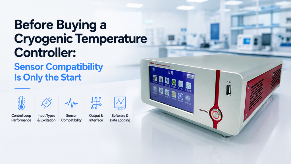
A common cryogenic instrument inquiry begins with one question:
“Does your temperature controller support Cernox?”
It is an important question.
But it is only the beginning.
A cryogenic temperature controller does much more than convert a sensor signal into a temperature reading. In a real cryogenic experiment, the controller may need to excite the sensor correctly, minimize sensor self-heating, store the correct calibration curve, drive one or more heaters, maintain stable PID control, switch between temperature ranges, communicate with other instruments, trigger alarms, and integrate with an automated measurement system.
Two controllers can both claim compatibility with the same temperature sensor and still behave very differently in the same cryostat.
For buyers, the correct question is therefore not simply:
“Which sensors are supported?”
It is:
“Can the complete controller–sensor–heater–cryostat combination measure and control the temperature range we actually need?”
This guide explains the parameters buyers should check before purchasing a cryogenic temperature controller.
1. First Separate Temperature Measurement from Temperature Control
This sounds obvious, but it causes a surprising amount of confusion in quotations.
A cryogenic temperature monitor primarily measures temperature.
A cryogenic temperature controller measures temperature and uses that measurement as feedback to control a heater or another thermal-control device.
The difference matters.
Temperature Monitoring May Require
- One or more sensor inputs
- Sensor excitation
- Resistance or voltage measurement
- Calibration curves
- Data logging
- Alarm functions
- Computer communication
Closed-Loop Temperature Control Also Requires
- A control sensor
- A target setpoint
- PID or another control algorithm
- A heater output
- Sufficient output power
- Compatible heater resistance
- Stable thermal coupling
- Appropriate control-loop tuning
A laboratory saying:
“We need to measure from 4 K to 300 K”
has not yet told the supplier whether it needs to control anywhere within that range.
That distinction should appear in the RFQ.
2. Sensor Compatibility Is More Than a Name in the Datasheet
Suppose a controller specification states:
“Supports Cernox, silicon diode, and Pt RTD sensors.”
That does not yet tell you everything required for a successful measurement.
For each sensor, buyers should check:
- Sensor electrical type
- Resistance or voltage range
- Required excitation
- Temperature range
- Calibration requirements
- Magnetic-field performance
- Number of wires
- Input resolution
- Self-heating limits
Commercial cryogenic controllers illustrate how important this distinction is. Lake Shore’s Model 350, for example, uses dedicated resistance-sensor inputs for Cernox and other RTDs, while additional input types such as diode, capacitance, and thermocouple sensors use different input configurations or option cards.
“Supported sensor” should therefore mean:
electrically measurable, correctly excitable, correctly calibrated, and usable over the required temperature range.
3. Cernox Compatibility: Ask Which Cernox and Over What Range
Cernox is not one universal resistance value.
Different Cernox models are optimized for different temperature ranges and resistance characteristics.
For example, Lake Shore lists different useful ranges for CX-1010, CX-1030, CX-1050, CX-1070, and CX-1080 variants. Depending on model, their useful lower temperature limits differ substantially.
That means:
“Supports Cernox”
is less useful than:
“Can this controller accurately read our specific Cernox model from 1.5 K to 300 K?”
Buyers Should Provide
- Exact sensor model
- Required temperature range
- Calibrated or uncalibrated sensor
- Number of sensors
- Whether the sensor will operate in magnetic field
- Whether it is used for monitoring or active control
This gives the supplier something technically meaningful to evaluate.
4. Calibration Curves Can Be More Important Than the Sensor Connector
Resistance thermometers do not produce a temperature directly.
They produce resistance.
The controller must convert that electrical response into temperature using an appropriate calibration relationship.
Cernox sensors, for example, require calibration; Lake Shore explicitly identifies Cernox RTDs as calibrated sensors rather than fully interchangeable devices following one universal curve.
Ask Whether the Controller Supports
- Factory sensor curves
- User-defined calibration curves
- Individual calibrated sensor data
- Curve upload from PC
- Curve editing
- Sufficient curve points
- Nonvolatile curve storage
Some commercial controllers can store dozens of user calibration curves and upload them from computer software. Lake Shore’s Model 336, for example, provides memory for calibrated or user curves and supports curve upload and editing.
Procurement Question
Do not ask only:
“Does it support Cernox?”
Ask:
“Can I upload and use the calibration table supplied with my exact sensor?”
That is much harder to misunderstand.
5. Standard Curve and Individual Calibration Are Not the Same
Some sensor families offer good interchangeability over certain ranges.
Others require individual calibration for high-accuracy work.
This affects purchasing because you may need to decide between:
- Uncalibrated sensor
- Standard-curve sensor
- Individually calibrated sensor
Why It Matters
The temperature controller may have excellent electrical resolution.
But if the sensor conversion curve is inaccurate, the displayed temperature can still be inaccurate.
A useful way to think about the complete measurement chain is:
Sensor behavior → electrical excitation → electrical measurement → calibration curve → displayed temperature
Every stage contributes to the result.
6. Sensor Excitation Is One of the Most Overlooked Specifications
Resistance sensors must be electrically excited before resistance can be measured.
The excitation may be specified as:
- Current
- Voltage
- AC excitation
- DC excitation
The correct level depends on the sensor and temperature range.
Too Little Excitation
The measured signal may become small compared with:
- Instrument noise
- Cable noise
- Electrical interference
Too Much Excitation
The sensor dissipates electrical power and heats itself.
Then the sensor can become slightly warmer than the object it is supposed to measure.
This is self-heating.
At cryogenic temperatures, that error can become extremely important.
7. Self-Heating Is Why “More Signal” Is Not Always Better
A resistance thermometer dissipates power when current flows through it.
For a resistive sensor:
P = I²R
Increasing excitation current increases the electrical signal—but also increases heating.
At very low temperatures, the sensor may have extremely weak thermal coupling to its surroundings.
Even a very small amount of measurement power can matter.
NIST specifically treats self-heating as an important uncertainty mechanism in cryogenic resistance thermometry and notes that excitation must be chosen carefully to avoid excessive sensor heating.
High-Performance Controllers Address This Differently
For example, Lake Shore’s Model 350 provides multiple excitation-current levels and automatically scales excitation to reduce self-heating as sensor resistance changes. Its ultra-low-temperature configuration can use excitation current down to the nanoampere level for appropriate measurements.
Buyer Question
Ask:
- What excitation levels are available?
- Are they manually selectable?
- Can the controller automatically change excitation?
- How does it prevent self-heating at the lowest temperature?
For a 300 K application, this may be secondary.
For a 300 mK application, it can be fundamental.
8. Your Minimum Temperature Should Drive the Input Architecture
A controller advertised for “cryogenic use” may cover a very broad category.
There is a major difference between systems designed for:
- 77 K
- 20 K
- 4.2 K
- 1.5 K
- 300 mK
- 100 mK
As temperature decreases:
- Sensor resistance may change dramatically
- Sensitivity changes
- Excitation requirements change
- Self-heating becomes more important
- Electrical noise becomes harder to ignore
- Thermal stabilization becomes slower
A controller suitable for a liquid-nitrogen experiment should not automatically be assumed to provide optimized performance in a sub-kelvin refrigerator.
RFQ Advice
Never write only:
“Cryogenic temperature controller required.”
Write:
“Required measurement and control range: 1.5 K to 300 K.”
That one line eliminates enormous ambiguity.
9. Number of Sensor Inputs Is Not the Same as Number of Control Loops
Another datasheet trap:
“Four sensor inputs.”
Buyers sometimes interpret this as:
“Four independent temperature-control channels.”
Not necessarily.
Sensor Inputs Answer
“How many temperatures can I measure?”
Control Loops Answer
“How many temperatures or thermal stages can I actively regulate independently?”
A controller might monitor:
- Sample
- Cold finger
- Radiation shield
- Magnet stage
but actively control only one or two of them.
Commercial controllers illustrate this difference clearly. Lake Shore’s Model 336 has four sensor inputs and four control outputs, but its primary architecture includes two major PID heater loops plus auxiliary outputs.
The exact relationship between inputs and outputs should always be checked.
10. Count the Thermal Stages Before Choosing the Controller
Consider a cryogenic experiment containing:
- Cold head
- Sample stage
- Radiation shield
- Magnet
- Heater stage
The laboratory may want to monitor all five temperatures.
But perhaps only the sample stage requires tight active regulation.
Another system may need to control:
- Sample temperature
- Shield temperature
- Still heater
- Auxiliary heater
simultaneously.
These systems need different controller architectures.
Buyers Should Define
For every sensor:
- Monitor only?
- Control sensor?
- Alarm sensor?
- Backup sensor?
And for every heater:
- Required maximum power?
- Heater resistance?
- Fine control or warm-up?
- Independent loop?
This is much more useful than asking for “four channels.”
11. Heater Output Power Can Make or Break the Control System
A cryogenic temperature controller may provide a heater output—but that does not mean the output can drive your heater properly.
The heater requirement depends on:
- Heater resistance
- Thermal mass
- Cooling power
- Required temperature range
- Desired warm-up speed
- Control stability
A Fine-Control Heater
A sample stage near its target temperature may need only:
- Milliwatts
- Hundreds of milliwatts
- Around one watt
A Warm-Up Heater
A larger cryogenic stage may need:
- Several watts
- Tens of watts
- Even more, depending on the system
Commercial ultra-low-temperature controllers can therefore provide very different heater outputs for different functions. The Model 350, for example, combines a higher-power warm-up output with a lower-power sample heater and additional auxiliary outputs.
Procurement Lesson
Do not ask only:
“How many heater outputs?”
Ask:
“What power can each output deliver into our actual heater resistance?”
12. Heater Resistance Must Match the Output Stage
Maximum wattage alone can also mislead.
Suppose a controller says:
“50 W heater output.”
Whether it can actually deliver 50 W depends on the connected load.
You should check:
- Heater resistance
- Maximum output voltage
- Maximum output current
- Maximum power
- Allowed load range
A 25 Ω heater and a 100 Ω heater may not receive the same maximum power from the same controller.
Send the Supplier
- Heater resistance
- Maximum required power
- Approximate operating temperature
- Whether the heater is already installed
If heater resistance is not yet defined, specify the cryostat and required thermal-control task so the controller and heater can be selected together.
13. One Heater May Need High Power and Another Needs Fine Resolution
Cryogenic systems often contain two different control objectives.
Fast Warm-Up
The objective is to move the system rapidly toward a higher temperature.
This favors:
- Higher heater power
Fine Temperature Stabilization
The objective is to hold the sample near a precise setpoint.
This favors:
- Low-noise output
- Fine resolution
- Stable PID control
- Appropriate low-power range
Using one oversized heater range for everything can make fine regulation more difficult.
A sophisticated controller may therefore provide multiple heater ranges or separate outputs optimized for different thermal jobs.
14. PID Is Not a Checkbox
Almost every modern temperature controller can advertise:
“PID control.”
That tells you very little about how it will behave in your cryostat.
PID performance depends on the complete thermal plant:
- Heater position
- Sensor position
- Thermal mass
- Thermal conductivity
- Cooling power
- Time delay
- Target temperature
The same PID values that work at 100 K may perform badly at 4 K.
Poor Tuning Can Produce
- Overshoot
- Oscillation
- Long settling time
- Temperature drift
- Slow response
Useful Controller Features
Depending on the experiment, look for:
- Manual P/I/D adjustment
- PID autotuning
- Multiple PID zones
- Setpoint ramping
- Automatic output-range selection
The Model 350, for example, supports manual PID adjustment, autotuning, setpoint ramping, and temperature-zone functions that can change settings across different temperature regions.
The lesson is not that every buyer needs all of these functions.
The lesson is that “PID available” is only the starting point.
15. Wide Temperature Ranges May Need Multiple Control Zones
A cryostat operating from 4 K to 300 K does not behave like one thermal system across the entire range.
As temperature changes:
- Heat capacity changes
- Thermal conductivity changes
- Cooling power changes
- Sensor sensitivity changes
- Heater effectiveness changes
One fixed PID configuration may therefore not perform well everywhere.
Zone-Based Control
Some controllers allow different temperature regions to use different:
- PID values
- Heater ranges
- Sensor inputs
- Excitation settings
This can be valuable for automated warm-up and cooldown experiments.
If your experiment routinely sweeps across hundreds of kelvin, ask about zone control.
If you only regulate around 77 K, you may not need it.
16. Sensor Switching Can Extend the Usable Temperature Range
No temperature sensor is ideal everywhere.
A system may use:
- Cernox at low temperature
- Silicon diode across a wider general cryogenic range
- Platinum RTD at higher temperature
- Thermocouple at still higher temperature
Some advanced controllers can automatically change the active control sensor as the temperature crosses predefined zones. The Model 336, for example, supports sensor switching across temperature zones to extend continuous measurement and control over a much wider range.
Procurement Question
Will the experiment require:
- One sensor over the entire range?
or
- Multiple sensors optimized for different ranges?
That can change both the controller and the cryostat wiring.
17. Magnetic Field Changes Sensor Selection
This is particularly important for the type of laboratory that also operates:
- Electromagnets
- Superconducting magnets
- Hall systems
- VSM systems
- Low-temperature magnetic measurements
A temperature sensor may work perfectly at zero field and show a field-dependent error inside a strong magnet.
Cernox Is Popular for a Reason
Cernox sensors were specifically developed for cryogenic applications where low magnetic-field-induced errors are valuable. Lake Shore documents their use across cryogenic temperatures and in substantial magnetic fields, depending on sensor model and operating condition.
Other Sensors Behave Differently
For example:
- Platinum RTDs have their own field limitations
- Silicon diodes can show magnetic-field effects
- Capacitance thermometers may be selected where magnetic-field dependence must be minimized
The correct sensor depends on:
- Temperature
- Magnetic field
- Required accuracy
- Calibration
- Cost
Buyer Question
Instead of:
“Does the controller support Cernox?”
ask:
“We need temperature measurement at 4 K in a 9 T magnetic field. Which sensor and input architecture should we use?”
That is a system-level question.
18. The Sensor Location Can Matter as Much as Sensor Accuracy
Imagine a controller displaying:
4.200 K
The number looks impressive.
But where is the sensor?
It may be measuring:
- Cold finger
- Sample holder
- Cryostat wall
- Magnet
- Heater block
—not the sample itself.
Temperature gradients can exist between these locations.
Common Causes
- Poor thermal contact
- High heat load through wiring
- Heater position
- Radiation
- Sample mounting
- Vacuum quality
- Optical heating
- Electrical dissipation
A highly accurate sensor in the wrong location can give a highly accurate measurement of the wrong temperature.
The controller cannot fix poor thermal design.
19. Two-Wire and Four-Wire Measurement Should Be Discussed
Resistance sensors are connected through wires that also have resistance.
In a two-wire measurement, lead resistance can contribute directly to the measured resistance.
For precision resistance thermometry, four-wire arrangements can substantially reduce this error by separating excitation and voltage-sensing paths.
This Becomes Important When
- Lead wires are long
- Sensor resistance is relatively low
- High measurement accuracy is required
- Cryostat wiring resistance changes with temperature
Buyers should confirm:
- Sensor wiring method
- Connector pinout
- Number of required feedthroughs
- Whether four-wire measurement is supported
This should be resolved before the cryostat wiring harness is built.
20. Thermal EMF Can Affect Resistance Measurements
Different metals and temperature gradients can create thermoelectric voltages in the wiring.
These unwanted voltages can contaminate very small sensor signals.
One method of suppressing such errors is reversing the sensor excitation current and combining the two measurements.
Lake Shore documents current reversal in its resistance-sensor inputs specifically to reduce thermal EMF errors.
Research Buyers Should Ask
Does the input architecture provide:
- Excitation reversal?
- Differential measurement?
- Electrical isolation?
- Appropriate filtering?
These details rarely appear in a simple question about “sensor compatibility.”
21. Electrical Isolation Matters in Complex Experiments
A temperature controller rarely operates alone.
The same experiment may contain:
- Magnet power supply
- Nanovoltmeter
- Current source
- Lock-in amplifier
- Cryostat
- Computer
- RF electronics
- Vacuum gauges
Grounding conflicts can create:
- Noise
- Measurement offsets
- Communication problems
- Ground loops
Isolated sensor inputs can help reduce interaction between different parts of the experiment. Commercial cryogenic controllers such as the Model 336 and Model 350 use isolated sensor-input architectures for this reason.
For a simple standalone cryostat, this may be less critical.
For a multi-instrument physics experiment, it deserves attention.
22. Temperature Resolution and Temperature Accuracy Are Different
A controller may display:
0.001 K
That does not mean the absolute temperature is known to ±0.001 K.
The complete uncertainty can include:
- Sensor calibration
- Input electronics
- Excitation
- Self-heating
- Lead resistance
- Magnetic-field effect
- Thermal gradients
- Mounting
- Long-term sensor stability
Three Different Questions
Buyers should separate:
Display resolution
How many digits can the instrument show?
Measurement resolution
What temperature change can it reliably detect?
Absolute accuracy
How close is the measured temperature to the actual temperature?
A serious quotation should not mix these concepts.
23. Stability Is Different from Accuracy Too
A research experiment may not require extremely high absolute accuracy.
It may instead need excellent stability.
For example, a measurement may require:
“Hold the sample at 10 K within a very narrow variation for four hours.”
That is a different requirement from:
“Measure the absolute temperature at 10 K to the smallest possible uncertainty.”
Temperature Stability Depends On
- Controller noise
- Sensor sensitivity
- PID tuning
- Heater resolution
- Cryostat design
- Environmental disturbances
- Cooling stability
Specify the real experimental objective.
24. Computer Interfaces Are No Longer an Optional Detail
A front-panel controller may be perfectly usable manually.
But modern research workflows often require integration with:
- Python
- LabVIEW
- MATLAB
- Custom automation software
- Magnet controllers
- Hall measurement software
- Data-acquisition systems
Common hardware interfaces include:
- Ethernet
- USB
- GPIB / IEEE-488
- RS-232 or other serial interfaces
For example, Lake Shore’s Model 350 provides Ethernet, USB, and IEEE-488 interfaces and allows most instrument functions to be operated remotely.
The Critical Question Is Not Only the Connector
Ask whether the manufacturer supplies:
- Command documentation
- Programming examples
- Drivers
- Remote setpoint control
- Sensor data access
- Heater-output readback
- Alarm status
- Curve management
An Ethernet connector without a usable command interface does not provide meaningful automation.
25. Think About Integration With Magnet and Transport Measurements
A cryogenic temperature controller may become one component of a larger measurement platform.
For example:
Hall Measurement
The software may need to coordinate:
- Temperature
- Magnetic field
- Measurement current
- Hall voltage
MOKE
The system may synchronize:
- Sample temperature
- Magnetic field
- Optical acquisition
VSM or Magnetic Characterization
The experiment may need:
- Temperature stabilization
- Field sweep
- Magnetic moment measurement
Automated Workflow
A sequence could be:
- Set 20 K
- Wait until stable
- Sweep magnetic field
- Record data
- Set 30 K
- Repeat
Without a usable remote interface, the operator may need to perform every temperature step manually.
26. Alarm and Interlock Functions Matter More Than Buyers Expect
Temperature control also involves equipment protection.
A controller may need to respond when:
- Temperature exceeds a limit
- Sensor becomes disconnected
- Heater output stays at maximum
- Cryogenic cooling fails
- Sample temperature rises unexpectedly
Useful functions may include:
- High alarm
- Low alarm
- Relay output
- Latching alarm
- Heater shutdown
- External interlock
The Model 350, for example, includes programmable temperature alarms and relay functions that can be used for fault signaling or simple control actions.
Buyer Question
What should happen if the temperature sensor fails during an unattended overnight experiment?
If there is no answer, the control architecture is incomplete.
27. Do Not Forget Sensor Failure Behavior
Suppose the control sensor wire breaks.
The controller suddenly reads an invalid temperature.
What happens to the heater?
Possible safe responses include:
- Heater turns off
- Alarm activates
- Relay changes state
- Software stops the experiment
This becomes especially important with:
- High-power heaters
- Valuable samples
- Superconducting magnets
- Long unattended experiments
Fail-safe behavior should be discussed before installation.
28. Manual Front-Panel Operation Still Matters
Automation is important, but laboratories should also consider what happens when the computer is unavailable.
Useful front-panel functions may include:
- Read all temperatures
- Change setpoint
- Adjust heater output
- Configure PID
- Select calibration curve
- View alarms
- Diagnose sensor wiring
A controller that can only perform basic functions through software may be inconvenient during commissioning and troubleshooting.
For laboratory instrumentation, local control and remote control should complement each other.
29. Number of Inputs Should Include Future Expansion
Suppose the current cryostat requires:
- Sample sensor
- Cold-head sensor
Two inputs appear sufficient.
Six months later, researchers add:
- Radiation-shield sensor
- Magnet-stage sensor
- Backup sample sensor
Now the two-channel controller is full.
But Do Not Overbuy Blindly
Eight channels are not automatically better than four.
Ask:
- How many sensors exist today?
- How many are likely within three years?
- Can a separate temperature monitor handle auxiliary sensors?
- Do all channels need control capability?
A temperature monitor can sometimes provide a cheaper expansion path than replacing the main controller.
30. A Controller and a Monitor Can Work Together
Complex cryogenic systems do not necessarily need one enormous controller.
A sensible architecture may be:
Main Controller
Handles:
- Sample control sensor
- Main heater
- Critical thermal stages
Multi-Channel Monitor
Handles:
- Radiation shield
- Magnet
- Cryostat wall
- Gas line
- Auxiliary stages
This can reduce cost while keeping the control architecture clear.
The correct choice depends on how many temperatures must be controlled, not merely observed.
31. Think About Future Sensor Types Before Purchase
Today’s experiment may use a silicon diode.
Tomorrow’s system may need:
- Cernox
- Pt RTD
- Ruthenium oxide
- Thermocouple
- Capacitance thermometer
Changing sensor family may require:
- Different excitation
- Different measurement range
- Different calibration curve
- Different connector
- Additional input module
Some controller families address this with configurable or field-installable input modules. The Model 350, for example, can expand its base RTD architecture with additional diode, capacitance, or thermocouple input options.
If future expansion is credible, ask about it before buying.
32. The Cheapest Compatible Controller May Become the Most Expensive Upgrade
Imagine two products.
Controller A
- Reads the current sensor
- One heater output
- Manual operation
- Limited curve storage
Controller B
- Multiple sensor inputs
- User calibration curves
- Multiple heater ranges
- Remote interface
- Programmable PID zones
- Expansion capability
If the experiment will never change, Controller A may be the correct purchase.
But if the laboratory later adds:
- New cryostat
- Low-temperature sensor
- Additional stage
- Automated magnetic-field measurement
Controller A may need to be replaced entirely.
The Opposite Is Also True
Do not buy Controller B merely because it has more features.
Future-proofing is valuable only when the future requirement is credible.
33. What Buyers Should Put in a Cryogenic Temperature Controller RFQ
A useful RFQ should answer the following.
Temperature Requirements
- Minimum temperature
- Maximum temperature
- Required control range
- Required stability
- Required accuracy
Sensor Information
- Sensor type
- Exact model if available
- Number of sensors
- Calibrated or uncalibrated
- Existing calibration files
- Monitoring or control function
Magnetic Environment
- Maximum magnetic field
- Sensor position relative to field
- Required field-dependent accuracy
Heater Information
- Number of heaters
- Heater resistance
- Maximum required power
- Fine-control or warm-up function
Control Requirements
- Number of independent control loops
- PID control
- Automatic tuning
- Setpoint ramping
- Zone control
Interface Requirements
- Ethernet
- USB
- GPIB
- Serial
- LabVIEW
- Python or custom software integration
Safety Requirements
- Alarms
- Relays
- Overtemperature protection
- Sensor-failure response
- External interlocks
Providing this information can turn a vague product inquiry into a technically meaningful system quotation.
34. A Weak RFQ vs. a Good RFQ
Weak RFQ
“We need a cryogenic temperature controller. Does it support Cernox? Please quote.”
The supplier still does not know:
- Which Cernox
- Temperature range
- Number of sensors
- Heater requirements
- Number of control loops
- Magnetic field
- Interfaces
Any immediate quotation will therefore contain assumptions.
Better RFQ
“We need a cryogenic temperature controller for a 4–300 K sample stage. One calibrated Cernox sensor will be used for closed-loop control, with two additional sensors for monitoring. The system operates inside a superconducting magnet. The sample heater is 50 Ω and requires approximately 1 W maximum. We need programmable PID control, setpoint ramping, Ethernet communication, user calibration-curve upload, and data acquisition from PC.”
Now the supplier can evaluate the actual application.
That is the difference between asking:
“Does it support my sensor?”
and asking:
“Can it control my cryogenic experiment?”
35. How Cryomagtech Approaches Cryogenic Temperature Controller Selection
Cryomagtech evaluates cryogenic temperature controller requirements around the complete measurement and thermal-control loop.
Important project inputs may include:
- Temperature range
- Sensor type and model
- Sensor calibration
- Excitation requirements
- Number of sensor inputs
- Number of control loops
- Heater resistance and power
- Magnetic-field environment
- PID requirements
- Computer interface
- Data-logging requirements
- Future expansion
For buyers already using a particular cryogenic sensor, we recommend providing the exact sensor model and calibration information before final controller selection.
Sensor compatibility is necessary.
It is not sufficient.
36. Practical Buyer Decision Checklist
Before choosing a cryogenic temperature controller, ask:
Sensor
- Does it support the exact sensor type?
- Does the electrical input range match?
- Is the correct excitation available?
- Can sensor self-heating be controlled?
- Can the calibration curve be uploaded?
- Is the sensor suitable for the magnetic field?
Measurement
- What is the real temperature range?
- What resolution is required?
- What absolute accuracy is required?
- What stability is required?
Control
- How many independent loops are required?
- What heater resistance will be used?
- How much heater power is needed?
- Are multiple heater ranges available?
- Are PID zones or ramping required?
Integration
- How many auxiliary temperatures must be monitored?
- Which computer interfaces are required?
- Can the controller be automated?
- Are programming commands documented?
- Are alarm and relay outputs required?
If several of these answers are missing, the controller specification is probably not finished.
37. Key Takeaways
- A cryogenic temperature controller cannot be selected from sensor compatibility alone.
- “Supports Cernox” should lead to questions about the exact sensor model, temperature range, excitation, calibration, and magnetic field.
- Resistance-sensor excitation must balance measurement signal against self-heating.
- Very-low-temperature measurements often require lower excitation and more careful input design.
- Calibration-curve capability is essential when using individually calibrated resistance thermometers.
- Sensor-input count and independent control-loop count are different specifications.
- Heater resistance and heater power must be evaluated together.
- High-power warm-up and fine sample control may require different output ranges.
- PID performance depends on the complete cryostat thermal system, not only on the controller.
- Wide temperature sweeps may benefit from multiple control zones and automatic sensor switching.
- Magnetic field can influence sensor selection and measurement accuracy.
- Remote communication, alarms, curve management, and software integration should be specified before purchase.
- A controller with the correct sensor connector can still be the wrong controller for the experiment.
The wrong purchasing question is:
“Does this controller support Cernox?”
The better question is:
“Can this controller measure our sensor correctly, drive our heater correctly, and maintain the temperature stability our experiment actually requires?”
References
- National Institute of Standards and Technology (NIST) — Calibration of Cryogenic Resistance Thermometers
NIST discusses excitation-dependent self-heating in cryogenic resistance thermometers and why excessive measurement power can introduce temperature errors.
https://nvlpubs.nist.gov/nistpubs/SpecialPublications/NIST.SP.250-91.pdf - Lake Shore Cryotronics — Model 350 Cryogenic Temperature Controller
Technical reference covering Cernox and other sensor inputs, excitation-current selection, self-heating reduction, calibration curves, PID outputs, heater control, alarms, and remote interfaces.
https://www.lakeshore.com/products/categories/overview/temperature-products/cryogenic-temperature-controllers/model-350-cryogenic-temperature-controller