
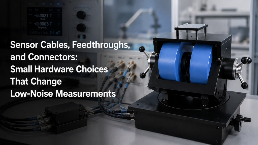
In low-noise laboratory measurements, customers often focus on the main instruments:
- Hall measurement system
- Cryogenic temperature controller
- Gaussmeter or teslameter
- Magnet power supply
- Lock-in amplifier
- Nanovoltmeter
- Data acquisition system
- Magnetic field feedback controller
But many measurement problems do not come from the main instrument.
They come from the small hardware between the sensor and the instrument:
- Sensor cables
- Feedthroughs
- Connectors
- Shielding
- Grounding
- Cable routing
- Contact quality
- Strain relief
- Adapter choices
For Hall measurements, cryogenic measurements, magnetic field feedback, and integrated control systems, small hardware choices can directly affect noise, drift, stability, and repeatability.
This article explains why cables, feedthroughs, and connectors matter in low-noise magnetic and cryogenic measurement systems.
1. Low-Noise Measurement Is a System Problem
A sensitive instrument cannot perform well if the signal path is poor.
For low-level measurements, the signal may be very small:
- Microvolt-level Hall voltage
- Low-current sensor output
- Resistance thermometer signal
- Cryogenic temperature sensor excitation
- Magnetic field probe output
- Feedback signal from a field sensor
- Weak sample voltage in magnetoresistance testing
At these levels, the measurement chain is only as strong as its weakest connection.
Tektronix/Keithley’s Low Level Measurements Handbook emphasizes that generated currents from input cables and induced currents from insufficient shielding can cause errors in sensitive measurements, and recommends low-noise cable and electrostatic shielding for connections and the device under test.
This is why cable and connector planning should not be treated as a final accessory decision.
It is part of the measurement design.
2. Sensor Cables Are Not Just Wires
A sensor cable does more than carry a signal.
It can also introduce:
- Electrical noise pickup
- Leakage current
- Thermal EMF
- Ground loops
- Cable motion noise
- Capacitance
- Crosstalk
- Contact resistance
- Mechanical stress
- Heat leak in cryogenic systems
For magnetic field and cryogenic systems, the cable may connect:
- Hall sensor to field meter
- Temperature sensor to controller
- Sample leads to measurement electronics
- Cryogenic probe to feedthrough
- Power supply feedback signal to controller
- Field sensor to closed-loop control system
If the cable is wrong, the signal may be unstable even when the sensor and instrument are good.
A low-noise system is not made by one expensive instrument.
It is made by a clean signal path.
3. Shielding: Protecting Small Signals from the Environment
Shielding helps reduce noise pickup from external electric fields and electromagnetic interference.
This is especially important near:
- Magnet power supplies
- High-current coil cables
- Switching power supplies
- Motors
- Chillers
- Compressors
- Control cabinets
- RF equipment
- Long cable runs
- Computer and USB devices
For low-level analog signals, shielded cables and twisted-pair wiring are common noise-reduction methods. Campbell Scientific’s measurement noise guidance notes that shielded cable and twisted pair wire are simple and effective methods for reducing noise in low-level signals, and that shields for low-frequency analog signals are often grounded at one end to avoid shield currents.
This point is important: shielding is not only about using a shielded cable.
It is also about how and where the shield is connected.
Poor shielding practice can sometimes create new noise problems.
4. Ground Loops: A Common Source of Hidden Noise
Ground loops happen when there is more than one ground path between parts of a system.
This can allow unwanted current to flow through the signal ground or cable shield.
Symptoms may include:
- 50/60 Hz hum
- Slowly drifting readings
- Different noise when equipment is plugged into different outlets
- Noise changes when a laptop charger is connected
- Noise changes when a chiller or motor starts
- Different readings depending on cable routing
Ground loops are common in systems that combine:
- Magnet power supply
- Measurement instrument
- Computer
- Sensor
- Cryostat
- Chiller
- Control cabinet
- DAQ module
- External trigger lines
The solution depends on the system. It may involve single-point grounding, differential measurement, isolation, shield termination strategy, or better cable routing.
Do not solve grounding problems by random trial and error unless the system is safe and low voltage.
For high-current magnet systems, grounding must also satisfy safety requirements.
5. Twisted Pair, Coaxial, Triaxial, and Shielded Multi-Core Cables
Different measurements need different cable types.
Twisted Pair
Useful for differential signals and reducing magnetic pickup.
Common for:
- Sensor leads
- Low-voltage analog signals
- Temperature sensor wiring
- Differential voltage measurements
Coaxial Cable
Useful when shielding and defined impedance are needed.
Common for:
- Higher-frequency signals
- Certain analog outputs
- Sensor signals
- Instrument connections
Triaxial Cable
Useful for very low-current or high-impedance measurements where guarding may be needed.
The Low Level Measurements Handbook explains that triaxial connections can support guarding by using an inner shield at guard potential and an outer shield connected to ground, while also warning that safety hazards can exist if guard voltage is high.
Shielded Multi-Core Cable
Useful when several signals must be routed together, but crosstalk and shielding must be managed.
Common for:
- Multi-sensor probes
- Cryogenic wiring harnesses
- Control signals
- Multi-axis systems
The correct cable depends on signal type, noise level, voltage, current, frequency, temperature, and mechanical movement.
6. Feedthroughs: Where Measurement Quality Often Changes
Feedthroughs are used when signals must pass through a boundary.
Examples include:
- Vacuum chamber wall
- Cryostat top plate
- Environmental chamber
- Shielded enclosure
- Glovebox
- Metal test chamber
- Water-cooled system panel
- Control cabinet wall
A feedthrough may look like a simple connector, but it can affect:
- Signal integrity
- Shield continuity
- Leakage current
- Thermal leakage
- Vacuum integrity
- Mechanical strain
- Grounding path
- Contact resistance
- Connector compatibility
- Serviceability
For cryogenic and vacuum systems, feedthroughs are especially important because they must satisfy both electrical and environmental requirements.
A poor feedthrough choice can make a good sensor noisy, unstable, or difficult to maintain.
7. Cryogenic Wiring: Electrical Noise and Heat Leak Must Both Be Controlled
In cryogenic measurement systems, wiring must balance two competing needs:
- Good electrical signal quality
- Low heat leak into the cold stage
Thick copper wires may reduce electrical resistance, but they also conduct more heat.
Thin or resistive wires reduce heat leak but may increase voltage drop, noise, or measurement limitations.
Cryogenic wiring may need:
- Low-thermal-conductivity materials
- Twisted pairs
- Shielded leads
- Thermal anchoring
- Strain relief
- Vacuum-compatible insulation
- Careful connector selection
- Sensor-specific wiring configuration
For temperature sensors and low-level sample measurements, wire type and routing can directly affect noise and thermal stability.
This is why cryogenic systems should not be wired like ordinary room-temperature benches.
8. Hall Measurements: Small Voltages Need Clean Wiring
Hall measurements are especially sensitive to wiring and contact quality.
A Hall voltage can be small, and the measurement may need to separate the true Hall signal from offset voltages, contact asymmetry, thermoelectric voltages, and noise.
The Lake Shore Hall Effect Measurement Handbook reviews major sources of measurement errors in Hall measurements and electronic transport characterization.
For Hall systems, cable and connector choices may affect:
- Voltage noise
- Current stability
- Contact resistance
- Reversal measurement quality
- Thermal offsets
- Sample heating
- Shielding effectiveness
- Measurement repeatability
This is why Hall measurement systems often require careful sample wiring, stable contacts, clean shielding, and proper measurement sequence.
A magnet and power supply alone do not guarantee clean Hall data.
9. Connectors: Contact Quality Matters
Connectors can introduce real measurement problems.
Common connector issues include:
- Loose contacts
- Oxidation
- Wrong pinout
- Poor shielding continuity
- Mixed connector materials
- Thermoelectric voltage
- Mechanical vibration
- Strain on solder joints
- Misalignment
- Intermittent connection
- Inadequate current rating
- Inadequate voltage rating
For low-noise systems, connectors should be selected based on:
- Signal level
- Current rating
- Voltage rating
- Shielding requirement
- Temperature range
- Vacuum or cryogenic compatibility
- Number of mating cycles
- Mechanical locking
- Pin assignment clarity
- Serviceability
A connector that is acceptable for control wiring may not be acceptable for microvolt-level measurement.
10. Thermoelectric EMF: Small Temperature Differences Can Create Voltage Errors
When two different metals meet at different temperatures, thermoelectric voltages can appear.
This matters in:
- Low-voltage Hall measurement
- Nanovoltmeter measurement
- Cryogenic sample wiring
- Temperature gradients
- Connector transitions
- Long measurement leads
- Warm-to-cold feedthroughs
- Mixed-metal terminal blocks
The error may be small in ordinary measurements but significant in microvolt-level signals.
Practical ways to reduce thermoelectric errors include:
- Keeping junctions at the same temperature
- Avoiding unnecessary metal transitions
- Using suitable low-thermal EMF connectors
- Allowing thermal stabilization
- Using current reversal or field reversal methods where appropriate
- Keeping connectors away from heat sources
If a measurement changes after touching a connector, moving a cable, or starting a nearby device, the problem may not be the sample.
It may be the connection environment.
11. Cable Motion Noise and Microphonics
Cable movement can create electrical noise.
This can happen through:
- Triboelectric effects
- Changing capacitance
- Mechanical stress at contacts
- Movement in magnetic fields
- Loose shielding
- Vibrating connectors
- Cryostat vibration
- Chiller vibration
- Motion stage cable drag
This matters for:
- Low-current measurements
- High-impedance sensors
- Cryogenic probes
- Moving sample stages
- Rotating fixtures
- Field mapping probes
- Magnetometer calibration systems
Low-noise cables, proper strain relief, and fixed routing can reduce motion-related noise.
In automated systems, cable routing should be designed together with motion paths.
Do not let cables freely swing near the measurement region.
12. High-Current Cables and Signal Cables Should Not Be Treated the Same
Magnet systems often include both high-current cables and low-level signal cables.
High-current cables may connect:
- Power supply to electromagnet
- Power supply to Helmholtz coil
- Amplifier to AC coil
- Control cabinet to load
Signal cables may connect:
- Field sensor
- Hall probe
- Temperature sensor
- Sample voltage leads
- Feedback sensor
- DAQ input
These cables should be separated when possible.
High-current cables can create:
- Magnetic pickup
- Voltage drop
- Heating
- Switching noise
- Electromagnetic interference
- Grounding complications
Low-level signal cables should be routed away from high-current paths, power cables, motors, relays, and switching devices.
Cable layout is part of measurement design, not housekeeping.
13. Feedthrough and Connector Labels Prevent Real Errors
Labeling sounds simple, but it prevents costly mistakes.
A good system should label:
- Sensor channels
- Current leads
- Voltage leads
- Temperature sensor leads
- Heater leads
- Field probe direction
- Feedthrough pinouts
- Shield connections
- Ground points
- Interlock connectors
- Communication ports
For overseas installations and remote support, labeling is especially important.
If the customer sends a photo during troubleshooting, clear labels allow the supplier to identify wiring quickly.
Without labels, support becomes slow and uncertain.
For complex cryogenic or magnetic systems, every connector should have a purpose that can be understood later by someone who did not build the system.
14. Remote Support Depends on Visible, Documented Connections
For overseas laboratories, many support tasks happen remotely.
The supplier may ask for:
- Photos of connectors
- Cable labels
- Feedthrough pinout
- Instrument screenshots
- Wiring diagram
- Sensor channel assignment
- Grounding connection photo
- Noise data before and after cable changes
Remote troubleshooting is much easier when the system includes:
- Labeled cables
- Clear pinout drawings
- Cable routing photos
- Connector part numbers
- Feedthrough diagrams
- Spare mating connectors
- Test points
- Standardized wiring colors
This is one reason why documentation and small hardware organization should be included in the system scope.
15. Common Mistakes in Low-Noise Signal Hardware
Common mistakes include:
- Using ordinary cables for low-level signals
- Running signal cables beside high-current magnet cables
- Grounding cable shields at random points
- Creating ground loops through multiple instruments
- Using unverified adapters
- Mixing connector materials in temperature gradients
- Ignoring feedthrough leakage
- Forgetting cable strain relief
- Moving cables during measurement
- Using magnetic connector hardware near sensors
- Not labeling feedthrough pinouts
- Treating cryogenic wiring as room-temperature wiring
- Assuming the instrument alone determines noise performance
These mistakes are easy to make because the hardware looks small.
But in low-noise measurement, small hardware can create big errors.
16. What to Check Before Finalizing a Measurement System
Before finalizing a Hall, cryogenic, magnetic feedback, or low-noise measurement system, check:
- Signal level
- Sensor impedance
- Required noise floor
- Cable length
- Cable type
- Shielding strategy
- Grounding strategy
- Connector type
- Feedthrough requirement
- Vacuum or cryogenic compatibility
- Temperature gradient
- Motion or vibration
- High-current cable routing
- Field sensor location
- Pinout documentation
- Spare connectors
- Remote troubleshooting needs
If the measurement is critical, do not leave cables and connectors to the last minute.
They should be reviewed as part of the system design.
17. How Cryomagtech Supports Low-Noise Measurement Integration
Cryomagtech supplies magnetic field systems, Hall-related measurement configurations, cryogenic temperature instruments, excitation power supplies, magnetic field sensors, and system integration support for research and industrial laboratories.
For low-noise and field-dependent measurement projects, we can help customers evaluate:
- Sensor cable selection
- Feedthrough and connector requirements
- Signal and power cable separation
- Hall measurement wiring considerations
- Cryogenic sensor wiring
- Magnetic field feedback signal paths
- Grounding and shielding boundaries
- Cable labeling and documentation
- Spare cable and connector planning
- Remote support readiness
Our goal is not only to provide the main instrument.
Our goal is to help customers build a complete measurement path where sensors, cables, feedthroughs, connectors, power supplies, and control software work together.
For low-noise measurements, the small hardware is not small.
It is part of the data quality.
References
- Tektronix / Keithley – Low Level Measurements Handbook
The handbook explains how input cables, generated currents, induced currents, shielding, guarding, and source impedance affect low-level measurement quality.
https://download.tek.com/document/LowLevelHandbook_7Ed.pdf - Lake Shore – Hall Effect Measurement Handbook
This guide reviews Hall measurement methods and major measurement error sources in electronic transport characterization.
https://qdusa.com/siteDocs/productBrochures/Lake_Shore_Hall_Effect_Handbook.pdf - Campbell Scientific – Preventing and Attacking Measurement Noise Problems
This guide discusses shielded cable, twisted pair wiring, grounding practices, and noise reduction in low-level measurement signals.
https://s.campbellsci.com/documents/us/technical-papers/mnoise.pdf
Key Takeaways
- Low-noise measurement quality depends on the full signal path, not only the main instrument.
- Sensor cables can introduce noise, leakage, motion effects, thermal EMF, and grounding problems.
- Shielding works only when the shield connection strategy is correct.
- Feedthroughs affect signal integrity, vacuum or cryogenic compatibility, leakage, and serviceability.
- Connectors must be selected for signal level, shielding, temperature, current rating, and mechanical reliability.
- Hall measurements and cryogenic measurements are especially sensitive to wiring and contact quality.
- High-current magnet cables should be separated from low-level signal cables whenever possible.
- Clear labels, pinout drawings, and spare connectors make remote support much easier.
In low-noise measurement systems, the cable is not just a cable.
It is part of the instrument.