
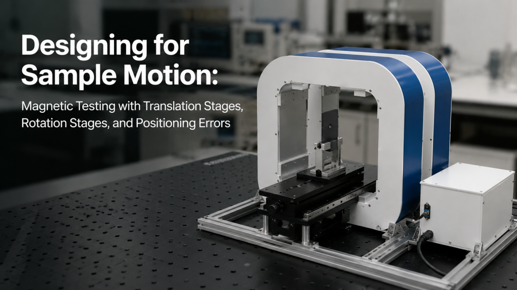
In many magnetic testing projects, the sample does not stay still.
It may need to move through a magnetic field.
It may need to rotate between field directions.
It may need to scan across a field map.
It may need to align with a sensor, optical path, probe, or cryogenic insert.
This creates a practical design question:
“How should the magnet system be designed when the sample must move?”
For electromagnets, Helmholtz coils, magnetic field calibration systems, material testing setups, and custom fixtures, sample motion is not just a mechanical detail. It can directly affect field strength, field uniformity, angular accuracy, repeatability, and data quality.
This article explains how translation stages, rotation stages, and positioning errors affect magnetic testing — and what buyers should check before ordering a system.
1. Why Sample Motion Matters in Magnetic Testing
Many customers define only the magnetic field requirement:
- 0.5 T electromagnet
- 100 mT Helmholtz coil
- ±1% uniformity
- 50 mm working space
- 3-axis field generation
But the real experiment may also require sample motion.
Examples include:
- Moving a sample through different field positions
- Rotating a sensor to test angular response
- Scanning a Hall probe across a field map
- Aligning a sample with optical access
- Moving a cryogenic probe into the field center
- Testing a magnetometer at multiple orientations
- Rotating a material sample under fixed magnetic field
- Translating a device under test through a uniform region
If motion is not considered early, the system may reach the target magnetic field but still fail to support the real experiment.
A magnet system should be designed around both the field and the motion path.
2. The Field Center Is Not Enough
Many magnet systems are specified by center-field performance.
For example:
“The field reaches 1 T at the center of the pole gap.”
That may be true.
But if the sample moves away from the center, the field may change.
For Helmholtz coils, the most uniform field is normally near the geometrical center. A practical Helmholtz coil application guide from Lake Shore defines field uniformity as being within a certain percentage of the center value over a specific cylindrical volume, which shows that uniformity is always tied to a defined region, not unlimited space.
So the real question is not only:
“What is the center field?”
The better question is:
“How much does the field change over the entire sample motion range?”
3. Translation Stages: Moving Through the Field
A translation stage moves the sample along one or more linear axes.
It may move along:
- X axis
- Y axis
- Z axis
- A diagonal path
- A scan line
- A plane
- A vertical insertion path
Translation stages are useful for:
- Field mapping
- Sample alignment
- Probe positioning
- Scanning measurements
- Multi-position testing
- Moving DUTs through a calibration region
- Positioning samples inside an electromagnet gap
- Placing a cryogenic probe at the field center
But translation creates a field-position problem.
If the magnetic field has a gradient, then small position changes can create measurable field changes.
This is not always a defect.
It may simply mean the sample has moved outside the best uniform region.
4. Positioning Error Becomes Field Error
In magnetic testing, positioning error can become field error.
For example, assume the magnetic field changes with position. If the sample is not placed at the intended coordinate, the recorded measurement may represent a different field than expected.
This matters for:
- Hall measurements
- Magnetoresistance testing
- Magnetometer calibration
- MOKE measurements
- Field mapping
- Material characterization
- Sensor response testing
Positioning error may come from:
- Stage repeatability
- Backlash
- Loose fixtures
- Manual adjustment
- Thermal expansion
- Cable pulling
- Stage sag
- Vibration
- Sample holder tolerance
- User handling
A small mechanical error may become a large measurement error if the field gradient is high.
This is why field uniformity and positioning repeatability should be considered together.
5. Rotation Stages: Changing Sample Orientation
A rotation stage changes the angular position of the sample.
It may rotate:
- Around one axis
- Around two axes
- Around three axes
- Manually
- With motorized control
- With encoder feedback
- Inside a coil system
- Between electromagnet poles
Rotation stages are useful for:
- Angular-dependent material testing
- Magnetometer calibration
- IMU and compass testing
- Magnetic anisotropy studies
- Hall probe alignment
- MOKE geometry adjustment
- Sample orientation studies
- Sensor package validation
But rotation introduces different errors from translation.
The sample may rotate, but its active sensing area may also shift away from the intended field center if the rotation axis is not aligned with the sample center.
6. Rotation Axis Error and Runout
A rotation stage is not perfect.
Important rotation-stage error terms may include:
- Angular accuracy
- Repeatability
- Backlash
- Reversal error
- Wobble
- Eccentricity
- Runout
- Tilt
- Center offset
- Lost motion
Rotation stage manufacturers often define and test these errors. For example, an MKS/Newport rotation stage manual describes eccentricity as displacement of the geometric center from the rotation axis and wobble as tilt of the rotation axis during rotation; it also references testing of accuracy, repeatability, and reversal error under controlled conditions.
For magnetic testing, these mechanical errors matter because the sample may not only rotate. It may also move slightly through the field.
If the field is not perfectly uniform over that motion envelope, the measurement may mix angular response with position-dependent field variation.
7. Backlash and Direction-Dependent Results
Backlash or lost motion can cause the final position to depend on the direction of approach.
For example, rotating to 30° from 0° may not produce exactly the same mechanical result as rotating to 30° from 60°.
OptoSigma describes lost motion measurement by positioning from forward and reverse directions and evaluating deviation at stop positions, which is directly relevant to repeatability in rotational positioning workflows.
In magnetic testing, this can produce confusing results:
- Up-angle sweep differs from down-angle sweep
- Repeated angles do not match exactly
- Calibration results depend on sweep direction
- Apparent magnetic hysteresis may partly be mechanical
- Sensor angular response appears noisier than expected
A good test method should define whether angles are always approached from the same direction or whether backlash compensation is used.
8. Fixture Material Matters
Sample motion requires fixtures.
Those fixtures must be selected carefully.
Avoid placing magnetic or conductive materials near the field region unless their effect is understood.
Problematic fixture materials may include:
- Steel screws
- Magnetic bearings
- Ferromagnetic brackets
- Motors near the sample
- Magnetized tools
- Conductive plates in AC fields
- Large aluminum parts near changing fields
- Unknown stainless steel parts
Preferred fixture materials often include:
- Non-magnetic stainless steel, if verified
- Aluminum, for some DC applications
- Brass
- Plastics
- Ceramics
- Fiberglass
- Non-magnetic fasteners
But material choice depends on the application.
For AC fields, even non-magnetic conductive materials may introduce eddy current effects. For low-field calibration, even small magnetic parts can be a problem.
The fixture is part of the magnetic environment.
9. Cable Motion Can Disturb the Measurement
Moving samples often have cables.
These may include:
- Sensor cables
- Probe wires
- Hall leads
- Thermometer wires
- Heater wires
- Signal cables
- Ground wires
- Coaxial cables
- Cryogenic wiring
- Motor cables
Cable motion can create problems:
- Pulling the sample away from position
- Changing grounding conditions
- Introducing electrical noise
- Creating thermal load
- Twisting during rotation
- Moving magnetic connector parts
- Changing loop area in a magnetic field
- Creating strain on fragile contacts
For precision testing, cable management is not cosmetic.
It affects repeatability.
A good motion design should include strain relief, flexible cable loops, clear cable paths, and separation between high-current magnet cables and sensitive signal cables.
10. Translation and Rotation Need Different Field Volumes
A fixed sample may only need a small uniform region.
A moving sample needs a larger usable field volume.
For translation, the uniform region must cover the full travel path where data is recorded.
For rotation, the uniform region must cover the complete envelope swept by the sample and holder.
For example, if a 20 mm long sensor package rotates around an axis that is 5 mm away from the sensing center, the effective swept volume may be larger than expected.
This matters for:
- Helmholtz coil size
- Electromagnet pole diameter
- Pole gap
- Sample holder design
- Field uniformity specification
- Field mapping plan
- Acceptance test region
A common mistake is specifying only the sample size while ignoring the motion envelope.
The supplier needs the full motion envelope, not only the sample dimensions.
11. Motion Can Affect Heat and Duty Cycle
Motion hardware can also change thermal design.
Possible heat sources include:
- Motorized stages
- Stepper motors
- Servo motors
- Encoders
- Drivers
- Control electronics
- Sample heaters
- Cryogenic thermal links
- Vacuum feedthroughs
- Friction or mechanical contact
Inside a compact magnet gap, Helmholtz coil, chamber, or cryogenic environment, this heat may matter.
Motion stages can also block airflow or cooling access.
For water-cooled magnets or coils, the motion system must not interfere with cooling hoses, flow sensors, or leak inspection.
Mechanical motion and thermal management should be reviewed together.
12. Automation Requires Timing Discipline
Automated motion is useful, but it does not remove the need for timing rules.
After a motion step, the system may need time for:
- Mechanical settling
- Vibration decay
- Sensor output stabilization
- Magnetic field settling
- Cable relaxation
- Stage position confirmation
- Thermal stabilization
If the software records data immediately after movement, the data may capture transient effects.
A better automated sequence may be:
- Move stage
- Confirm position
- Wait for mechanical settling
- Set or confirm magnetic field
- Wait for field settling
- Record data
- Log position, field, time, and status
This is slower than blind automation, but the data is more trustworthy.
Fast automation without validation is just fast error generation.
13. Motion Accuracy Should Match the Experiment
Not every project needs a high-end positioning system.
The required motion accuracy depends on the experiment.
Low-demand applications
Manual adjustment may be enough for:
- Demonstrations
- Rough alignment
- Basic sample positioning
- Non-critical screening
Medium-demand applications
A simple translation or rotation stage may be enough for:
- Repeatable material testing
- Sensor checks
- Basic angular response measurement
- Small field scans
High-demand applications
Precision stages may be needed for:
- Calibration systems
- Automated field mapping
- Magnetometer and IMU calibration
- Angular-dependent measurement
- High-gradient fields
- Small samples
- Long repeated sequences
Do not buy motion precision blindly.
Match the motion system to the field gradient, sample size, and measurement uncertainty target.
14. Field Mapping Should Include the Motion Path
If sample motion matters, field mapping should not only measure the center point.
It should verify the relevant path or region.
Examples include:
- Field along the translation axis
- Field over the sample scan line
- Field over a 2D plane
- Field over the rotation envelope
- Field at key angular positions
- Field before and after fixture installation
- Field with the stage present
- Field with cables and holder installed
This is especially important when fixtures, stages, or chambers are made of materials that may influence the field.
For serious acceptance, the measured field region should match the actual test region.
A field map that ignores the sample motion path may not answer the real question.
15. What Buyers Should Provide Before Requesting a Quote
Before requesting a magnet system with sample motion, prepare:
- Sample size
- Sample weight
- Required motion type
- Translation range
- Rotation range
- Required positioning accuracy
- Required repeatability
- Motion speed
- Manual or motorized control
- DUT cable information
- Fixture material preference
- Working temperature
- Field direction
- Required field uniformity volume
- Motion envelope drawing
- Available installation space
- Whether motion must be synchronized with field control
- Whether data logging is required
A simple sketch is often enough for the first review.
But for custom systems, suppliers need more than “we need rotation” or “we need movement.”
They need to understand how motion is used in the measurement.
16. Common Mistakes in Sample Motion Design
Common mistakes include:
- Designing only for the static field center
- Ignoring the full motion envelope
- Using magnetic screws or brackets near the sample
- Placing motors too close to the field region
- Ignoring stage backlash
- Ignoring cable drag
- Assuming rotation does not change sample position
- Forgetting mechanical settling time
- Using field maps that do not cover the motion path
- Choosing a compact magnet gap before checking fixture clearance
- Treating motion accuracy and magnetic uniformity as separate issues
- Recording data immediately after motion without validation
The harsh truth is simple:
If the sample moves, the magnetic requirement moves with it.
17. How Cryomagtech Supports Magnetic Testing with Sample Motion
Cryomagtech supplies electromagnets, Helmholtz coil systems, 3-axis magnetic field systems, excitation power supplies, fixtures, and custom system integration support for research and industrial laboratories.
For projects involving sample motion, we can help customers evaluate:
- Static vs moving sample requirements
- Translation and rotation stage integration
- Working volume and motion envelope
- Field uniformity across the motion path
- Fixture material and sample holder design
- Cable routing and strain relief
- Manual vs motorized operation
- Positioning repeatability considerations
- Field mapping and acceptance scope
- Software synchronization between field and motion
Our goal is not only to generate a magnetic field.
Our goal is to help customers design a test environment where the sample can be positioned, moved, measured, and repeated with confidence.
A magnet system should match the real experiment — including how the sample moves.
References
- Lake Shore – Helmholtz Coil Application Guide
The guide defines magnetic field uniformity over a specified cylindrical volume, showing why the usable field region must be matched to the sample and motion envelope.
https://www.lakeshore.com/docs/default-source/product-downloads/manuals/f011-05-00.pdf - MKS/Newport – Rotation Stage User Manual
The manual describes rotation stage error concepts such as eccentricity, wobble, repeatability, and reversal error, which are directly relevant when rotating samples in magnetic testing.
https://api.p1.mks.com/medias/sys_master/images/images/hb2/hea/9131988516894/URS-B-User-s-Manual.pdf - OptoSigma – Measurement of Rotation Stage Accuracy
OptoSigma explains how lost motion and repeatability are evaluated by positioning from forward and reverse directions, relevant to direction-dependent stage errors.
https://www.optosigma.com/uk_en/product-guides/motorized-stages/measurement-of-rotation-stage-accuracy
Key Takeaways
- Sample motion changes the magnetic testing problem.
- Translation stages require field uniformity along the actual movement path.
- Rotation stages introduce angular error, eccentricity, wobble, backlash, and possible position shift.
- Positioning error can become field error when the sample moves through a field gradient.
- Fixture material, cable motion, and stage construction can affect magnetic measurements.
- Motion envelope is more important than sample size alone.
- Field mapping should cover the real motion path, not only the static center point.
- Automated motion requires position confirmation, settling time, and synchronized data logging.
Do not design a magnet system only around where the sample starts.
Design it around everywhere the sample must move.