When laboratories plan a magnetometer or IMU calibration setup, one architecture question appears very early:
“Should we keep the DUT fixed and change the magnetic field vector, or rotate the DUT inside a magnetic field?”
Both approaches can work.
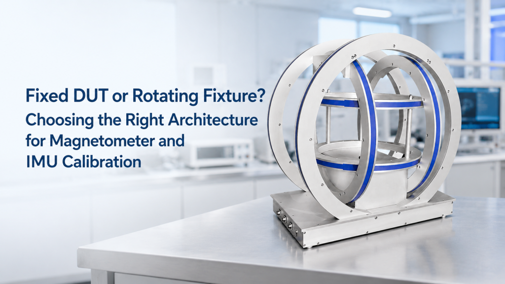
A fixed-DUT system can use a 3-axis Helmholtz coil to generate controlled magnetic field vectors around the device under test.
A rotating-fixture system can physically rotate the magnetometer, IMU, compass module, or sensor package through different orientations.
The right choice depends on calibration goal, accuracy requirement, mechanical constraints, automation level, cable behavior, and whether the user needs to simulate geomagnetic vector conditions.
This article explains the difference between fixed-DUT and rotating-fixture architectures for magnetometer and IMU calibration.
1. What Is the DUT in Magnetometer and IMU Calibration?
DUT means “device under test.”
In this context, the DUT may be:
- 3-axis magnetometer
- Digital compass module
- IMU
- AHRS sensor
- Navigation sensor
- MEMS sensor package
- Smartphone or wearable sensor module
- Drone navigation module
- Vehicle compass unit
- Downhole sensor
- Marine or aerospace magnetic sensor
An IMU usually includes accelerometers and gyroscopes, while some systems also integrate magnetometers for heading or orientation reference. Magnetometers measure magnetic field and can support heading estimation when properly calibrated.
For many of these devices, calibration is not only about one magnetic field value. It is about how the sensor responds to magnetic field direction, amplitude, offset, alignment, and cross-axis effects.
2. The Two Basic Architectures
There are two common calibration architectures:
Architecture A: Fixed DUT + Controlled Magnetic Field
The DUT stays mechanically fixed.
A 3-axis Helmholtz coil or magnetic field generation system creates different magnetic field vectors around the DUT.
This approach changes the field, not the device position.
Architecture B: Rotating Fixture + Fixed or Controlled Field
The DUT is mounted on a rotating fixture, turntable, gimbal, or multi-axis stage.
The magnetic field may be Earth’s field, a controlled field from a coil system, or a partially compensated field environment.
This approach changes the DUT orientation, not only the applied field.
Both methods can produce useful calibration data, but they answer different engineering questions.
3. Fixed DUT Architecture: How It Works
In a fixed-DUT architecture, the sensor remains in one mechanical position while the coil system generates magnetic fields along different axes.
A typical setup may include:
- 3-axis Helmholtz coil
- Three independent current channels
- Stable excitation power supplies
- Field sensor or reference magnetometer
- Non-magnetic DUT holder
- Control software
- Calibration procedure
- Optional magnetic shielding or compensation
This method is especially useful when the goal is to apply known magnetic vectors without disturbing cables, connectors, fixtures, or the DUT’s mechanical state.
A 3-axis Helmholtz coil approach is commonly used in magnetic sensor calibration research, including procedures where triaxial magnetometers are calibrated using controlled fields without physically rotating the sensor.
4. Advantages of Fixed DUT Calibration
A fixed-DUT approach can be attractive when:
- The DUT has cables that should not move
- The DUT is fragile or heavy
- The sensor must remain installed in a fixture
- The test requires automated field sequences
- The calibration needs repeatable magnetic vectors
- Mechanical rotation would introduce alignment errors
- The user wants to simulate different geomagnetic field directions
- The sensor is part of a larger assembly
This architecture reduces mechanical uncertainty.
If the DUT does not move, then cable bending, connector stress, fixture backlash, and repeatability of mechanical positioning become less important.
For production or repeated lab testing, this can make the process cleaner and more automatable.
5. Limits of Fixed DUT Calibration
Fixed-DUT calibration is powerful, but it has limits.
It requires a magnetic field generation system with good control over:
- Field amplitude
- Field direction
- Axis orthogonality
- Field uniformity
- Current stability
- Center positioning
- Cross-axis coupling
- Background field compensation
If the 3-axis coil is not well designed or calibrated, the generated vector field may not be accurate enough.
Also, fixed-DUT calibration may not fully test mechanical orientation effects, such as:
- Mounting misalignment
- Sensor package alignment relative to enclosure
- Gravity-related IMU behavior
- Accelerometer response during orientation changes
- Real-world rotation behavior
So fixed-DUT calibration is excellent for magnetic vector control, but it may not replace every mechanical orientation test.
6. Rotating Fixture Architecture: How It Works
In a rotating-fixture architecture, the DUT is physically moved through different orientations.
The fixture may be:
- Single-axis turntable
- Two-axis gimbal
- Three-axis rotation stage
- Manual rotary fixture
- Motorized calibration rig
- Non-magnetic sample holder
- Custom mechanical jig
The magnetic environment may be Earth’s field, a controlled Helmholtz coil field, or a shielded/compensated field.
This approach is common when the calibration needs to evaluate the sensor response as the device orientation changes.
7. Advantages of Rotating Fixture Calibration
A rotating fixture can be useful when:
- The DUT must be tested in different physical orientations
- The calibration includes accelerometer or gyroscope behavior
- The user wants heading response across rotation angles
- Mechanical mounting errors must be evaluated
- The DUT is compact and easy to rotate
- A lower-cost setup is preferred
- The field environment is stable enough
- Manual calibration is acceptable
For IMUs, physical orientation can matter because accelerometers and gyroscopes respond to motion, orientation, and rotation. If the goal is full inertial sensor behavior, rotating the device may be necessary.
A magnetometer-only calibration may be possible with controlled fields, but an IMU-level calibration often requires thinking about both magnetic and mechanical orientation.
8. Limits of Rotating Fixture Calibration
Rotating the DUT introduces mechanical error sources.
These may include:
- Rotation axis misalignment
- Fixture backlash
- Encoder accuracy
- Cable twisting
- Connector movement
- DUT position shift
- Non-magnetic material selection
- Ferromagnetic screws or bearings
- Motor magnetic interference
- Repeatability of manual positioning
- Rotation center not matching sensor center
For high-accuracy magnetometer calibration, these details matter.
A rotating fixture that contains steel parts or magnetic motors too close to the DUT can disturb the very field being measured.
Also, cable movement can change sensor output indirectly if the cable pulls on the DUT, changes grounding, or moves nearby magnetic materials.
9. The Most Important Question: What Are You Calibrating?
The architecture should follow the calibration goal.
If the goal is magnetometer scale, offset, and cross-axis response
A controlled 3-axis magnetic field system can be highly effective.
The DUT can stay fixed while the field vector changes.
If the goal is compass heading response in real orientations
A rotating fixture may be useful because the device physically changes direction.
If the goal is full IMU calibration
Rotation is often needed because accelerometers and gyroscopes are part of the measurement.
If the goal is production screening
A fixed-DUT coil system may improve automation and reduce fixture wear.
If the goal is field simulation
A 3-axis Helmholtz coil is often better because it can generate controlled vector fields without physically moving the DUT.
The wrong architecture can produce data, but not the data the customer actually needs.
10. Geomagnetic Simulation: Why 3-Axis Helmholtz Coils Matter
Many magnetometer and compass calibration tasks operate near Earth-field levels.
A 3-axis Helmholtz coil can generate controlled magnetic field components along X, Y, and Z axes. This allows the system to create different vector field directions and magnitudes around the DUT.
This is useful for:
- Magnetometer calibration
- Compass testing
- IMU heading validation
- AHRS sensor evaluation
- Geomagnetic field simulation
- Navigation sensor testing
- Sensor array calibration
- Magnetic disturbance studies
Controlled-field systems are especially helpful when the lab wants repeatable magnetic conditions instead of relying only on the local Earth field.
NIST’s magnetic sensing and metrology program describes magnetometers, vector and scalar magnetic measurements, uniform field environments, and magnetic field calibration capabilities, showing why controlled and traceable field conditions matter in serious magnetic measurement work.
11. Fixed DUT vs Rotating Fixture: Practical Comparison
| Factor | Fixed DUT + 3-Axis Coil | Rotating Fixture |
|---|---|---|
| Main control variable | Magnetic field vector | DUT orientation |
| Mechanical movement | Low | Medium to high |
| Cable disturbance | Lower | Higher |
| Automation potential | High | Medium to high |
| Field vector control | Strong if coil is calibrated | Depends on field environment |
| IMU orientation testing | Limited | Stronger |
| Magnetometer vector calibration | Strong | Possible, but mechanically dependent |
| Fixture complexity | Lower mechanically, higher electrically | Higher mechanically |
| Risk of magnetic materials in fixture | Lower if simple holder | Higher if stage contains metal/motors |
| Best use case | Controlled magnetic field simulation | Orientation-dependent device testing |
This table is not a ranking.
It shows that the two architectures solve different problems.
12. Hybrid Architecture: Sometimes the Best Answer
In many serious calibration projects, the best architecture is hybrid.
That means:
- Use a 3-axis Helmholtz coil to generate controlled fields
- Use a simple non-magnetic fixture to position the DUT
- Add limited rotation only where needed
- Keep motors, steel parts, and cables away from the uniform field region
- Use software to coordinate field steps and mechanical positions
A hybrid system can support both magnetic vector control and selected orientation testing.
This is often useful for:
- IMU calibration
- Compass module validation
- Navigation sensor testing
- Sensor fusion experiments
- Production test rigs
- R&D calibration benches
But hybrid systems must be designed carefully because each added mechanical function can introduce magnetic or alignment errors.
13. What Information Suppliers Need Before Recommending an Architecture
Before requesting a calibration system quote, customers should prepare:
- DUT size and weight
- Sensor type and axis definition
- Magnetometer-only or full IMU calibration
- Required field range
- Required field uniformity
- Required field vector directions
- Calibration accuracy target
- Manual or automated test process
- Need for rotation angle control
- Cable and connector constraints
- Allowed magnetic materials near DUT
- Test volume
- Throughput requirement
- Software and data output needs
- Existing equipment to be reused
Without these details, it is easy to quote the wrong architecture.
A customer may ask for a rotating fixture when a fixed-DUT coil system would be more stable.
Or they may ask for a 3-axis coil when the real requirement is full IMU orientation testing.
The architecture should be chosen after the calibration workflow is understood.
14. Common Mistakes in Magnetometer and IMU Calibration Setup
Common mistakes include:
- Treating magnetometer calibration and IMU calibration as the same task
- Using a metal rotation stage inside the field region
- Forgetting cable twisting and connector stress
- Assuming Earth’s field is stable enough for every test
- Ignoring nearby ferromagnetic structures
- Using a 1-axis coil for a 3-axis sensor problem
- Requesting high uniformity without defining test volume
- Placing motors too close to the DUT
- Ignoring axis alignment between coil, fixture, and sensor
- Expecting software correction to solve poor hardware geometry
The biggest mistake is choosing hardware before defining the calibration method.
15. How Cryomagtech Supports Calibration System Architecture
Cryomagtech supplies Helmholtz coil systems, 3-axis magnetic field systems, electromagnets, excitation power supplies, and custom calibration-related configurations for overseas laboratories and industrial users.
For magnetometer and IMU calibration projects, we can help customers evaluate:
- Fixed DUT vs rotating fixture architecture
- 1-axis, 2-axis, or 3-axis field generation
- Required magnetic field range
- Uniformity volume
- DUT holder and fixture constraints
- Non-magnetic mechanical design
- Power supply and control requirements
- Remote installation and training scope
- Field mapping and acceptance support
Our goal is not to force every project into the same structure.
Our goal is to match the calibration architecture to the actual measurement problem.
For some customers, a fixed DUT inside a controlled 3-axis field is the cleanest solution.
For others, a rotating fixture is necessary.
For many serious calibration benches, a carefully designed hybrid system may be the best answer.
References
- NIST – Magnetic Sensing and Metrology
NIST describes magnetic measurement capabilities including magnetometers, vector and scalar magnetic measurements, uniform field environments, and calibration capabilities.
https://www.nist.gov/programs-projects/magnetic-sensing-and-metrology - Ground Calibration with Orthogonality Correction for Tri-Axial Fluxgate Magnetometer
This article describes a method involving a magnetometer placed inside a Helmholtz coil while applying magnetic fields along X, Y, and Z axes without rotating the magnetometer.
https://www.janss.kr/archive/view_article?pid=jass-41-4-271
Key Takeaways
- Fixed-DUT and rotating-fixture architectures solve different calibration problems.
- A fixed DUT inside a 3-axis Helmholtz coil is strong for controlled magnetic vector generation.
- A rotating fixture is useful when real device orientation, heading response, or full IMU behavior must be tested.
- Rotation introduces mechanical errors, cable disturbance, and possible magnetic interference.
- Fixed-DUT systems require well-controlled coil axes, field uniformity, and current stability.
- Hybrid systems can combine controlled fields with selected mechanical orientation tests.
- The best architecture depends on calibration goal, DUT constraints, automation needs, and acceptable error sources.
Do not choose the fixture first.
Choose the calibration method first — then design the magnetic field system and mechanical architecture around it.