
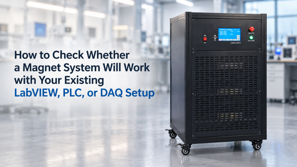
For many engineering laboratories, purchasing a magnet system is not a standalone equipment decision.
The laboratory may already have:
- LabVIEW software
- NI DAQ hardware
- PLC control cabinets
- Industrial PCs
- Existing temperature controllers
- Optical instruments
- Hall probes
- Current or voltage sensors
- Automated test sequences
The new electromagnet, Helmholtz coil, or excitation power supply is expected to become part of that existing architecture.
This leads to a common RFQ statement:
“The magnet system must be compatible with LabVIEW.”
Unfortunately, that sentence is not specific enough to confirm compatibility.
A power supply may have USB, RS-232, RS-485, Ethernet, or analog control and still require substantial integration work before LabVIEW can operate it.
Likewise, an instrument may communicate perfectly with LabVIEW but still be unsuitable for a PLC-based production system or a hardware-triggered DAQ experiment.
To evaluate magnet system integration correctly, buyers should separate four different layers:
Physical interface → Communication protocol → Command/control layer → Timing and system architecture
This article explains how to check each layer before purchasing a magnet system.
1. “Compatible with LabVIEW” Can Mean Several Different Things
Two suppliers may both answer:
“Yes, LabVIEW is supported.”
But they may mean completely different things.
Supplier A
Provides:
- USB port
- Documented ASCII command set
- LabVIEW example VI
Supplier B
Provides:
- RS-232 communication
- Communication protocol document
- No LabVIEW driver
Supplier C
Provides:
- ±10 V analog current command
- Analog current monitor
- TTL trigger
- No digital command interface
Supplier D
Provides:
- Ethernet
- Modbus TCP
- PLC register map
All four systems may potentially be integrated into an automated laboratory.
But the engineering effort is very different.
The correct question is therefore not:
“Does it support LabVIEW?”
Ask:
“Exactly how will my controller send commands to the magnet system and receive status or measurement data?”
2. Start with the Control Architecture
Before discussing connectors, define what the laboratory actually wants to control.
A magnet system may contain:
- Electromagnet or Helmholtz coil
- Excitation power supply
- Hall probe
- Gaussmeter
- Temperature sensor
- Chiller
- Interlocks
- PLC
- Control computer
The external LabVIEW or PLC may need control over only one component—or the complete system.
For example:
Architecture A — Current Control Only
LabVIEW controls the power supply current.
The laboratory’s own DAQ measures everything else.
Architecture B — Field Control
LabVIEW commands a target magnetic field.
A field sensor and local controller close the magnetic-field feedback loop.
Architecture C — Complete Experiment Control
LabVIEW coordinates:
- Field
- Temperature
- Optical source
- Sample current
- Data acquisition
These are very different integration requirements.
3. Decide Which System Should Be the Master Controller
One of the most important architecture questions is:
Who is in charge?
Possible master controllers include:
- Supplier’s Windows software
- LabVIEW
- PLC
- Industrial PC
- Real-time controller
- Customer DAQ application
Avoid architectures where two controllers can independently command the same power supply without clearly defined ownership.
For example:
- Supplier software commands +10 A.
- PLC simultaneously commands 0 A.
- LabVIEW requests −5 A.
Which command wins?
A well-defined system should have one clear control hierarchy.
4. The First Layer Is the Physical Interface
Start by asking which physical interfaces are actually available.
Typical examples include:
- USB
- RS-232
- RS-485
- Ethernet
- GPIB
- CAN
- Analog ±10 V
- 0–10 V
- 4–20 mA
- Digital I/O
- TTL trigger
This tells you how signals physically enter and leave the instrument.
It does not yet tell you what those signals mean.
5. A USB Port Does Not Automatically Mean LabVIEW Control
This is an important distinction.
USB may be used for:
- Virtual COM port
- Vendor-specific USB protocol
- USBTMC instrumentation
- Firmware update only
- Data logging
- Dedicated manufacturer software
Therefore, asking:
“Does it have USB?”
is weaker than asking:
“Can the USB interface be controlled through a documented protocol, and is that protocol accessible through LabVIEW?”
The same principle applies to Ethernet.
6. NI-VISA Can Simplify Instrument Communication
For LabVIEW laboratories, one useful integration path is a message-based instrument interface accessible through VISA.
NI describes VISA as a standard instrumentation I/O API. NI-VISA can provide access to instruments using interfaces including serial, USB, Ethernet, GPIB, PXI, and VXI.
This can be useful when a power supply supports a documented command interface such as:
- ASCII commands
- SCPI-like commands
- Serial command strings
- TCP socket commands
A simplified LabVIEW sequence might look conceptually like:
- Open VISA session
- Send current command
- Read status
- Read measured current
- Repeat
- Close session
But VISA solves only the communication-access layer.
It does not invent the command language of the instrument.
7. Ask for the Command Set, Not Just the Port
Suppose a magnet power supply uses RS-232.
That still does not tell the programmer how to control it.
The supplier should ideally provide commands for functions such as:
- Set current
- Read current
- Enable output
- Disable output
- Change polarity
- Read voltage
- Read fault status
- Clear fault
- Identify instrument
For example, a conceptual command set might look like:
SET:I 5.000MEAS:I?OUTPUT ONFAULT?
The exact syntax will vary by manufacturer.
Without documentation, the customer may physically connect to the instrument but have no reliable way to operate it.
8. A LabVIEW Driver Is Helpful—but Not Always Necessary
Buyers often request:
“Please provide a LabVIEW driver.”
That can be valuable.
But a dedicated LabVIEW driver is not always mandatory if the supplier provides:
- Stable communication protocol
- Complete command documentation
- Example messages
- Response format
- Error codes
A competent LabVIEW programmer can often build a custom VI around a documented command set.
Therefore, distinguish between:
Native LabVIEW Driver Available
Lowest integration effort.
LabVIEW Example Available
Useful starting point.
Protocol Document Only
Integration possible but customer programming required.
Proprietary Software Only
External control may be limited.
These should not all be described simply as “LabVIEW compatible.”
9. VISA Compatibility Does Not Define the Magnet-Control Logic
Suppose LabVIEW can successfully send:
Current = 10 A
That proves communication.
It does not prove:
- Correct field
- Correct polarity
- Safe sweep rate
- Field stabilization
- Cooling status
- Interlock handling
Therefore, system integration needs both:
communication logic
and
magnet-control logic.
10. PLC Integration Usually Needs a Different Mindset
A PLC-based laboratory often prioritizes:
- Reliability
- Defined states
- Interlocks
- Deterministic sequences
- Industrial communication
Rather than sophisticated scientific user interfaces.
Typical PLC communication may involve:
- Modbus RTU
- Modbus TCP
- Profinet
- EtherNet/IP
- OPC UA
- Analog I/O
- Digital I/O
The correct interface depends on the existing automation architecture.
11. RS-485 Does Not Automatically Mean Modbus
This is another common procurement mistake.
RS-485 describes an electrical communication layer.
Modbus defines a communication protocol.
A device can use:
RS-485 + Modbus RTU
but it could also use:
RS-485 + proprietary protocol.
The Modbus Organization describes Modbus as an application-layer protocol that can operate over different underlying communication networks, including serial and Ethernet implementations.
Therefore:
RS-485 port ≠ guaranteed Modbus compatibility.
Always ask for the actual protocol.
12. Modbus Integration Requires a Register Map
If the supplier states:
“Modbus supported,”
the next question should be:
“Please provide the Modbus register map.”
A useful register map may define:
- Target current
- Actual current
- Output voltage
- Output enable
- Polarity
- Temperature
- Fault code
- Interlock status
It should also specify:
- Register address
- Data type
- Scaling
- Read/write permission
- Byte order where relevant
Without this information, “Modbus supported” remains incomplete.
13. Modbus TCP and Modbus RTU Are Not the Same Connection
The control engineer should know whether the proposed system uses:
Modbus RTU
Often transmitted over:
- RS-485
- Serial communication
Modbus TCP
Communicated through:
- Ethernet
- TCP/IP
The underlying protocol concepts are related, but network configuration and physical architecture differ.
That distinction should be clear before the equipment arrives.
14. OPC UA May Be Relevant for Higher-Level Automation
For larger industrial or institutional systems, OPC UA may be used to exchange structured information between:
- Controllers
- Instruments
- SCADA
- Manufacturing systems
- Enterprise software
The OPC Foundation describes OPC UA as a platform-independent architecture intended to support information exchange and command/control between diverse industrial devices and systems.
This may be attractive for a large automated laboratory.
But it is normally far more capability than a simple benchtop magnet experiment needs.
Architecture should follow the actual project.
15. Analog Control Can Be Extremely Useful
Digital communication is not always the best solution.
Many excitation power supplies provide an external analog command such as:
±10 V command → ±100% current
For example:
- +10 V → +20 A
- +5 V → +10 A
- 0 V → 0 A
- −5 V → −10 A
- −10 V → −20 A
This can integrate naturally with a DAQ analog-output channel.
Advantages can include:
- Simple architecture
- Fast updates
- Easy waveform generation
- No serial command latency
But analog control also has limitations.
16. Analog Command Accuracy Depends on Both Devices
If a DAQ generates ±10 V to command magnet current, final accuracy depends on:
- DAQ analog-output accuracy
- Power-supply analog-input accuracy
- Noise
- Scaling
- Ground reference
- Cable quality
Therefore, specifying:
External ±10 V control
does not automatically define field accuracy.
The complete signal chain must be considered.
17. Ask Whether Analog Control Is Current Command or Voltage Command
A power supply may provide analog input for:
- Output current
- Output voltage
- Field command
- Some selectable function
These are not equivalent.
For electromagnet operation, laboratories often want current regulation because magnetic field is primarily controlled through magnet current.
Verify exactly what the analog signal controls.
18. Analog Monitor Outputs Can Be Equally Important
Useful power supplies may provide outputs such as:
- Current monitor
- Voltage monitor
- Fault state
- Temperature alarm
For example:
0–10 V output = measured current
This allows the customer’s DAQ to record the real power-supply response independently of the command signal.
That is valuable for automated experiments.
19. Command Signal and Measurement Signal Should Be Separated
Suppose LabVIEW sends:
5.000 V
to command approximately 10 A.
Do not automatically record:
Current = 10 A
in the experimental dataset simply because that was the requested value.
Where measurement accuracy matters, record actual feedback from:
- Power-supply current monitor
- Digital measured current
- Current transducer
- Field sensor
The difference is:
setpoint vs measured value.
20. A Field Feedback Signal May Be More Valuable Than Current Feedback
For precision magnetic-field experiments, the laboratory may care about:
B
rather than:
I.
The system can therefore include:
- Hall probe
- Gaussmeter
- Analog field output
- Digital field readout
This allows LabVIEW or another controller to record the actual field.
For higher-precision systems, it may also be used for closed-loop field regulation.
21. Decide Where the Closed Loop Should Run
This is a major architecture decision.
Imagine:
Target = 100 mT
There are at least three approaches.
Current-Controlled Open Loop
LabVIEW commands current using a calibration curve.
PC-Based Field Feedback
LabVIEW reads the gaussmeter and adjusts power-supply current.
Local Embedded Field Controller
The magnet controller closes the field loop internally, while LabVIEW sends only the desired field.
These architectures have different:
- Response times
- Stability
- Software complexity
- Failure modes
For demanding applications, the feedback-loop location should be defined before purchase.
22. Avoid Slow PC Loops for Fast Control Requirements
A Windows PC running LabVIEW can be excellent for:
- Supervisory control
- Sequence management
- Data logging
- Slow feedback
But normal desktop software is not necessarily deterministic enough for every high-speed control loop.
If the experiment requires tightly controlled real-time response, consider:
- Dedicated controller
- FPGA
- Real-time platform
- Local power-supply control
rather than assuming a conventional Windows loop will always be sufficient.
23. DAQ Integration Requires a Timing Discussion
Many laboratories say:
“We use NI DAQ.”
That still leaves several important questions:
- Analog input?
- Analog output?
- Digital I/O?
- Counter?
- Trigger?
- Hardware timing?
- Sample clock?
These determine what synchronization is actually possible.
NI’s DAQmx documentation distinguishes software-controlled operations from hardware triggers and synchronized timing. It supports analog and digital trigger mechanisms, including start and reference triggers for acquisition.
This matters when magnet state must be synchronized with another measurement.
24. Software Timing and Hardware Timing Are Different
Suppose LabVIEW performs:
- Set field
- Wait 100 ms
- Read detector
This is software-sequenced timing.
For many quasi-static magnetic experiments, that is perfectly acceptable.
But another experiment may require:
- External trigger edge
- Synchronized analog acquisition
- Precise waveform timing
That may require hardware-based triggers rather than software delays.
The buyer should therefore define timing accuracy, not merely automation.
25. TTL Trigger Inputs Can Be Valuable
A magnet controller or power supply may provide digital trigger functions such as:
- Start sweep
- Enable output
- Capture status
- Advance sequence
Similarly, the system may provide outputs such as:
- Field stable
- Sweep complete
- Fault
- Ready
These signals can simplify synchronization with:
- DAQ
- Laser
- Camera
- Spectrometer
- Oscilloscope
For tightly synchronized measurements, a simple TTL line can sometimes be more useful than an elaborate Ethernet interface.
26. Ask What the Trigger Actually Does
“Trigger input available” is not enough.
Ask:
- Voltage level?
- TTL?
- Rising or falling edge?
- Minimum pulse width?
- What action occurs?
- What is the response latency?
- Can the trigger be disabled?
- Is there a trigger output?
The trigger must match the intended experiment.
27. “Field Stable” Is Different from “Command Received”
Suppose LabVIEW commands:
500 mT
The power supply may acknowledge the command immediately.
But the magnetic field may require time to settle.
An integrated system may therefore need separate states:
- Command accepted
- Current reached target
- Field reached tolerance
- Measurement ready
For precision automated measurements, this distinction is important.
28. Define the Field-Settling Criterion
A measurement sequence might require:
Do not collect data until field is within ±0.1% of target for 500 ms.
That is far more precise than:
Wait 1 second after changing field.
The correct approach depends on:
- Magnet inductance
- Power supply
- Field sensor
- Measurement speed
If settling logic matters, it should be discussed during integration.
29. Power-Supply Inductance Limits Matter
An electromagnet is an inductive load.
The power supply must change current through that inductance.
This affects:
- Ramp rate
- Voltage requirement
- Field reversal
- Dynamic waveform capability
Therefore, an external DAQ producing a perfect high-frequency waveform does not guarantee that the magnet field will reproduce it.
The complete chain is:
DAQ waveform → power-supply response → magnet L/R behavior → magnetic field
All four must be considered.
30. DC, Low-Frequency, and Dynamic Field Control Are Different Projects
A magnet system may be excellent for:
- DC magnetic field
but unsuitable for:
- 100 Hz sinusoidal field
because of:
- Coil inductance
- Power-supply voltage
- Eddy-current effects
- Thermal load
Therefore, if LabVIEW or DAQ will generate waveforms, specify:
- Frequency range
- Amplitude
- Waveform
- Number of axes
- Continuous duration
during the RFQ stage.
31. Four-Quadrant Power Supplies Change Integration Possibilities
For experiments requiring smooth bipolar current, a four-quadrant supply can provide controlled operation through:
- +I
- 0
- −I
and can actively source or sink power depending on load and operating mode.
This is particularly relevant for:
- Automated hysteresis
- Fast field reversal
- Waveform generation
- Bipolar Helmholtz coils
The control interface should be evaluated together with the power topology.
32. A Relay-Reversed Supply Is Not Equivalent to Four-Quadrant Control
Two systems may both claim:
±20 A operation
but achieve it differently.
System A
Electronic four-quadrant bipolar operation.
System B
Unipolar supply + polarity relay.
Both may be acceptable for slow static experiments.
But System B may be poorly suited to:
- Smooth zero crossing
- Frequent reversal
- Dynamic waveforms
Therefore, automation requirements should influence power-supply selection.
33. PLC Projects Need Defined State Machines
A PLC often benefits from clear operating states such as:
- OFF
- READY
- RUN
- FAULT
- EMERGENCY STOP
The PLC may also monitor:
- Cooling
- Overtemperature
- Magnet current
- Door interlock
- External enable
This is more robust than treating the power supply as a single analog output.
For industrial-style systems, defining these states early can simplify commissioning.
34. Safety Interlocks Should Not Depend Only on LabVIEW
A PC application should not normally be the only protection against conditions such as:
- No cooling water
- Coil overtemperature
- Overcurrent
- Emergency stop
Critical safety and hardware protection functions should usually exist at the equipment/control level according to the system design.
LabVIEW or PLC can monitor their status.
But losing a Windows communication connection should not remove basic equipment protection.
35. Clarify What Happens When Communication Is Lost
This is an excellent pre-purchase question:
What happens if Ethernet, USB, or serial communication disappears while the magnet is energized?
Possible behaviors include:
- Maintain current
- Ramp to zero
- Disable output
- Enter fault
- Wait for timeout
No single behavior is universally correct.
The correct response depends on the experiment and safety architecture.
But it should be known before commissioning.
36. PLC Communication Failure Needs the Same Discussion
If the power supply is controlled through Modbus and the PLC stops communicating:
- Does the last command remain active?
- Is there a watchdog?
- Can timeout be configured?
- Does output turn off?
This should be part of the control specification.
37. Remote Enable Is Useful for System-Level Control
Some excitation supplies provide:
- External enable
- Inhibit
- Interlock input
A PLC or safety system can then determine whether magnet output is permitted.
This is different from continuously commanding current.
A useful architecture can separate:
Permission to operate
from
requested operating value.
38. Digital Status Outputs Can Simplify PLC Integration
Useful hardwired status signals may include:
- Ready
- Output enabled
- Fault
- Overtemperature
- Cooling OK
Even when digital communication exists, these simple signals can be valuable for machine-level interlocks.
39. LabVIEW, PLC, and DAQ May All Be Used Together
A sophisticated laboratory does not necessarily choose only one.
For example:
PLC
Handles:
- Safety
- Chiller
- Interlocks
- Equipment state
LabVIEW
Handles:
- Experimental sequence
- User interface
- Magnet commands
- Data management
DAQ
Handles:
- Analog signals
- Timing
- Hardware triggers
- High-speed acquisition
This can be an excellent architecture if responsibilities are clearly separated.
40. Avoid Duplicate Measurement Paths Unless They Serve a Purpose
Suppose:
- Power supply reports current digitally.
- DAQ reads current monitor analog signal.
- External ammeter measures current.
That may be useful for validation.
But if all three values appear in the software without clear naming, users can become confused.
Define which value is:
- Command
- Internal feedback
- External verification
Data architecture should be intentional.
41. Synchronizing Magnet Control with Optical Measurements
MOKE and magneto-optical experiments may require coordination between:
- Magnetic-field sweep
- Laser
- Detector
- Lock-in amplifier
- Camera
A possible sequence is:
- Set field
- Wait for stability
- Trigger acquisition
- Read optical signal
- Advance field
For slow hysteresis measurements, software sequencing may be enough.
For dynamic experiments, hardware triggering may become necessary.
42. Synchronizing Magnet Control with Hall Measurements
An automated Hall system may require:
- Set +B
- Wait
- Apply +I
- Measure voltage
- Apply −I
- Measure
- Set −B
- Repeat
That means LabVIEW may need to control:
- Power supply
- Current source
- Switching matrix
- Voltmeter
- Temperature controller
A documented command architecture becomes very important as instrument count increases.
43. Synchronizing Magnet Control with Cryogenic Experiments
A low-temperature experiment may involve:
- Temperature controller
- Magnet power supply
- Vacuum instruments
- Measurement electronics
The experiment may require:
At each temperature → wait for temperature stability → run magnetic-field sequence
This is a supervisory automation problem.
It rarely requires high-speed real-time control, but it does require:
- Reliable communications
- Error handling
- Status queries
- Sequence logic
44. Ask Whether External Control Locks Out the Local Front Panel
Some instruments allow:
- Simultaneous local and remote operation.
Others enter:
- Remote mode
and lock the front panel.
Either approach can work.
But users should know:
- Can an operator manually override current?
- Does remote control disable local buttons?
- How is control returned locally?
This matters during troubleshooting.
45. Ask Whether Supplier Software Can Run Simultaneously
Another common question is whether:
- Manufacturer software
- Customer LabVIEW program
can connect to the instrument at the same time.
Sometimes:
- Yes.
Sometimes:
- Only one communication session is allowed.
Sometimes:
- Two programs can connect but commands may conflict.
Do not assume multi-client control unless documented.
46. Driver Version and Operating System Matter
A LabVIEW integration that worked on one computer may depend on:
- NI-VISA version
- USB driver
- Windows version
- .NET runtime
- Vendor driver
For long-life research equipment, buyers should retain:
- Drivers
- Manuals
- Example code
- Protocol documentation
Protocol-level integration often has better long-term survivability than relying entirely on one proprietary application.
47. Open Protocols Can Reduce Lifecycle Risk
If the instrument exposes a documented protocol, the laboratory has more options later.
For example, the same equipment may eventually be controlled through:
- LabVIEW
- Python
- C#
- MATLAB
- PLC gateway
This is particularly valuable for university systems expected to operate for many years.
It does not mean every project needs an open API.
But long-term software strategy is worth considering.
48. Cybersecurity Matters for Network-Connected Systems
If a magnet controller sits on an institutional Ethernet network, ask:
- Fixed IP or DHCP?
- Which ports are used?
- Is authentication supported?
- Can remote write control be disabled?
- Does it need internet access?
For isolated laboratory LANs, requirements may be simple.
For corporate or national-laboratory networks, IT approval can become part of installation.
Discuss it before shipment.
49. Do Not Put Real-Time Control on the Cloud
Cloud access can be useful for:
- Monitoring
- Logging
- Diagnostics
But critical real-time control should not normally depend on unpredictable internet latency.
Keep time-critical and safety-critical control close to the equipment.
Remote supervisory access is a different layer.
50. A Compatibility Test Should Happen Before the PO Where Possible
For important projects, ask the supplier for enough information to perform an integration review before ordering.
Useful materials include:
- Communication protocol
- Command list
- Modbus register map
- LabVIEW example
- Analog I/O specification
- Trigger description
- Connection diagram
The buyer’s automation engineer can then determine whether integration is straightforward.
That is much better than discovering after delivery that:
“Ethernet” means only the supplier’s proprietary Windows application.
51. Example Code Is Stronger Evidence Than “Supported”
Suppose LabVIEW is mandatory.
Evidence strength might look like:
Strong
Working LabVIEW VI + protocol documentation.
Good
Protocol documentation + successful communication example.
Moderate
Documented VISA-accessible command set.
Weak
“USB supported.”
The more critical integration is, the stronger evidence buyers should request.
52. Ask for a Simple Remote-Control Demonstration
For major projects, a useful pre-shipment test can be:
- Connect external PC
- Send target current
- Read actual current
- Reverse polarity
- Read fault/status
- Return to zero
If this works through the promised interface, much of the communication risk is already reduced.
53. Test With the Customer’s Real Control Architecture When Integration Is Critical
For particularly important projects, factory or pre-shipment integration testing may use:
- Customer PLC model
- NI DAQ model
- Representative LabVIEW VI
- Same communication protocol
This is not necessary for every project.
But it can be valuable when integration failure would delay a large installation.
54. Define Who Writes the Integration Software
This is a commercial issue as much as a technical issue.
Possible arrangements include:
Supplier Responsibility
Supplier delivers complete LabVIEW integration.
Customer Responsibility
Supplier provides protocol; customer programs its own solution.
Shared Responsibility
Supplier controls magnet subsystem; customer integrates it into the overall experiment.
This should be explicit in the quotation.
Otherwise:
Customer thinks:
“LabVIEW compatible means you will write our LabVIEW application.”
Supplier thinks:
“LabVIEW compatible means we provide RS-232 commands.”
Both believe they agreed.
They did not.
55. Clarify Whether Integration Support Is Included
Integration may require:
- Calls with engineers
- Protocol troubleshooting
- Example code
- Remote testing
- Custom commands
For complex projects, clarify whether this support is:
- Included
- Limited
- Optional engineering service
before PO.
56. A Practical Compatibility Matrix
Before purchasing, create a simple table.
| Requirement | Existing Lab | Magnet System | Compatible? |
|---|---|---|---|
| Main control | LabVIEW | External digital control | Check |
| Interface | Ethernet | Ethernet | Physical only |
| Protocol | VISA TCP/IP | ASCII TCP | Likely |
| Set current | Required | Supported | Yes |
| Read current | Required | Supported | Yes |
| Bipolar control | Required | ±I supported | Yes |
| Analog command | ±10 V | ±10 V input | Yes |
| Trigger input | TTL | TTL input | Verify logic |
| Field feedback | Analog AI | Gaussmeter output | Yes |
| PLC protocol | Modbus TCP | Optional | Confirm |
| Fault output | Digital input | Relay output | Confirm |
| Emergency stop | Hardwired | Interlock | Yes |
Notice that matching connectors alone is only the first row of the engineering analysis.
57. Questions for LabVIEW Users
Before requesting a quotation, tell the supplier:
Communication
- LabVIEW version
- Windows version
- Preferred interface
- VISA required?
- Existing instrument drivers?
Commands
- Set current?
- Set magnetic field?
- Read current?
- Read voltage?
- Read field?
- Read fault?
Automation
- Field sweep?
- Repeated sequence?
- Temperature coordination?
- External instruments?
Timing
- Software timing sufficient?
- Hardware trigger required?
- Required response time?
This makes “LabVIEW compatible” measurable.
58. Questions for PLC Users
Specify:
PLC Platform
- Siemens
- Allen-Bradley
- Beckhoff
- Mitsubishi
- Omron
- Other
Communication
- Modbus RTU
- Modbus TCP
- Profinet
- EtherNet/IP
- OPC UA
- Analog I/O
Control
- Current setpoint
- Output enable
- Reset fault
- Field setpoint
Feedback
- Current
- Voltage
- Field
- Temperature
- Fault
- Interlock status
Safety
- Hardware emergency stop
- Watchdog
- Communication-loss behavior
This lets the supplier design the correct interface.
59. Questions for DAQ Users
Provide:
- DAQ model
- Analog-output range
- Analog-input range
- Digital I/O levels
- Trigger requirements
- Sample rate
- Hardware timing requirement
Then define:
- What signal the DAQ will generate
- What signal it will measure
For example:
AO0: ±10 V magnet-current command
AI0: ±10 V current monitor
AI1: ±10 V gaussmeter field output
PFI0: measurement trigger
That is much more useful than saying:
“We have NI DAQ.”
60. A Better RFQ for LabVIEW Integration
Instead of:
The system must support LabVIEW.
Write:
Our laboratory uses LabVIEW on Windows. We require external control of magnet current, output enable, bipolar polarity, and current/status readback. Ethernet or RS-232 communication is acceptable. Please provide the communication protocol and available LabVIEW example VI or VISA command documentation. Data must also include actual current and fault status.
Now the supplier can give a meaningful answer.
61. A Better RFQ for PLC Integration
Instead of:
PLC communication required.
Write:
The magnet system will be integrated into an existing Siemens PLC architecture. Modbus TCP or Profinet is preferred. Required functions include current setpoint, output enable, actual current readback, fault status, and cooling interlock status. Please provide protocol/register documentation and communication-loss behavior.
This immediately exposes compatibility boundaries.
62. A Better RFQ for DAQ-Controlled Field Generation
Instead of:
DAQ control required.
Write:
We use an NI multifunction DAQ. We prefer external ±10 V analog control corresponding to bipolar magnet current, with analog current monitor and TTL trigger capability. Required waveform range is DC–10 Hz. Please confirm command scaling, input impedance, monitor scaling, bandwidth, and magnet/power-supply response with the proposed load.
Now both sides understand the real experiment.
63. How Cryomagtech Approaches Automation Integration
Cryomagtech magnet and field-generation systems can be evaluated according to the customer’s existing automation architecture rather than assuming one universal control method.
Depending on the project, integration requirements may include:
- Excitation power supply
- Bipolar current control
- Analog ±10 V command
- Current monitoring
- USB / serial / Ethernet communication
- External triggering
- Magnetic-field feedback
- LabVIEW integration
- PLC communication
- DAQ control
- Automated field sequences
👉 Product link placeholder: Cryomagtech Excitation Power Supplies & Bipolar Magnet Power Supplies
For complete magnetic-field projects:
👉 Product link placeholder: Cryomagtech Electromagnet & Helmholtz Coil Systems
For customized projects, providing the existing LabVIEW / PLC / DAQ architecture during the RFQ stage can help define the correct communication interface before manufacturing begins.
64. Key Takeaways
Checking magnet system integration with LabVIEW, PLC, or DAQ requires more than comparing connector names.
Buyers should verify four layers.
Layer 1 — Physical Interface
- USB
- RS-232
- RS-485
- Ethernet
- Analog
- Digital I/O
Layer 2 — Protocol
- VISA-accessible command interface
- Proprietary serial protocol
- Modbus RTU
- Modbus TCP
- OPC UA
- Analog scaling
Layer 3 — Control Capability
- Set current
- Set field
- Enable output
- Reverse polarity
- Read current
- Read field
- Read faults
Layer 4 — Timing and System Architecture
- Software sequence
- Hardware trigger
- Closed-loop feedback
- PLC state machine
- Real-time requirements
- Safety interlocks
The most important procurement principle is:
A matching connector proves that two devices can be physically connected.
A documented protocol proves that they can exchange information.
A defined control architecture proves that they can actually perform the experiment together.
Before purchasing a magnet system for an automated laboratory, define all three.
That can prevent one of the most common integration failures in research equipment procurement:
a magnet power supply that works perfectly on its own—but cannot participate in the laboratory workflow the customer actually intended.
References
1. National Instruments — NI-VISA and NI-DAQmx
NI documentation describes VISA as a standard instrumentation I/O API that can provide a common programming interface across serial, USB, Ethernet, GPIB, and other instrument connections. NI’s DAQmx documentation also distinguishes software sequencing from hardware triggering and synchronization, which is important when integrating magnet control with timed data acquisition.
Check source:
NI – Using VISA in LabVIEW
Check source:
NI – DAQmx Triggering Techniques Using LabVIEW
2. Modbus Organization — Modbus Protocol
The Modbus Organization defines Modbus as an application-layer protocol used for exchanging process information between industrial devices and explains that Modbus can operate over different underlying physical networks. This is why an RS-485 or Ethernet connector alone does not establish Modbus compatibility.
Check source:
Modbus Organization – Introduction to Modbus
Check source:
Modbus Organization – Protocol Specifications