
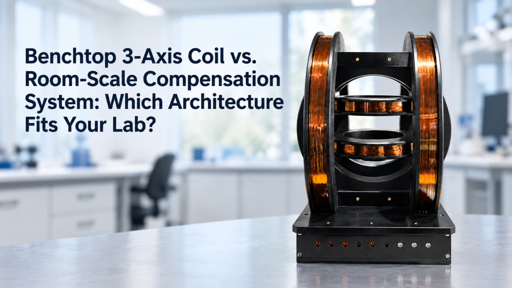
A customer asking for a 3-axis Helmholtz coil system may actually be describing two very different experiments.
One laboratory may want to place a magnetic sensor inside a desktop coil set and generate controlled X, Y, and Z magnetic fields for calibration.
Another may want to reduce Earth’s field, elevator disturbances, vehicle interference, or building magnetic noise across a large experimental area.
Both projects involve three-axis magnetic-field control.
But they are not the same system.
A benchtop 3-axis coil is primarily a local field-generation and calibration platform.
A room-scale magnetic compensation system is primarily an environmental field-control platform.
The distinction affects almost everything:
- Coil size
- Uniform-field volume
- Maximum field
- Sensor architecture
- Feedback control
- Field mapping
- Gradient compensation
- Power electronics
- Installation
- Cost
- Commissioning
This article explains how buyers can determine which architecture actually fits their laboratory before requesting a quotation.
1. Start with the Question: Generate a Field or Remove a Field?
This is the most important distinction.
Benchtop 3-Axis Coil
The primary question is:
What magnetic field do we want to generate at the device under test?
Typical objectives include:
- Sensor calibration
- Magnetometer characterization
- Geomagnetic-field simulation
- Compass testing
- Device orientation testing
- Low-field materials research
Room-Scale Compensation System
The primary question is:
What unwanted magnetic field exists in the laboratory, and how much of it must be cancelled over the experimental space?
Typical objectives include:
- Ambient magnetic-field cancellation
- Reduction of low-frequency interference
- Compensation of Earth’s field
- Stabilization of sensitive magnetometers
- Biomagnetic experiments
- Quantum sensing
- Large low-field experimental zones
These two questions lead to very different system architectures.
2. What a Conventional 3-Axis Helmholtz Coil Actually Does
A conventional Helmholtz pair consists of two similar coils positioned coaxially and separated by approximately one coil radius.
This geometry is designed to produce a relatively uniform magnetic field around the midpoint between the coils. (wikipedia.org)
A three-axis system combines three approximately orthogonal coil pairs.
The result allows independent control of:
- Bx
- By
- Bz
and therefore the total magnetic-field vector.
Typical operation might involve:
- +50 µT X
- −20 µT Y
- +10 µT Z
or:
- Rotate a constant-magnitude field through different directions
- Sweep one axis while keeping the others fixed
- Cancel Earth’s field at one defined central location
This makes three-axis Helmholtz coils highly useful for controlled local magnetic-field experiments.
3. Benchtop Systems Are Built Around a Defined Central Working Volume
A benchtop system usually has one clearly defined region of interest.
That may contain:
- Magnetometer
- IMU
- Electronic compass
- Magnetic sensor
- Small device
- Biological sample
- Test fixture
The engineering question is normally:
How large must the controlled uniform-field region be?
For example:
- 30 × 30 × 30 mm
- 50 mm DSV
- 100 × 100 × 100 mm
- Larger customized volumes
The coil geometry is then optimized around that local region.
The entire room does not need to experience the same field.
4. Room-Scale Compensation Starts with a Completely Different Volume
A room-scale system may need to control the magnetic environment across:
- An optical table
- A human-sized measurement region
- A large cryogenic apparatus
- Multiple magnetometers
- A cubic-meter experimental zone
Now the design question becomes:
How much of the room must remain magnetically controlled?
That change in scale is fundamental.
A compensation system capable of producing excellent cancellation at one point may perform poorly one meter away.
Therefore, room-scale design is driven by spatial field distribution, not simply center-field strength.
5. A Large Coil Is Not Automatically a Room Compensation System
One common misunderstanding is:
“If we make the Helmholtz coil much larger, we have a room-scale compensation system.”
Not necessarily.
A large three-axis Helmholtz structure can generate controlled fields over a larger region.
But real laboratory magnetic disturbances may include:
- Uniform background field
- Spatial gradients
- Localized magnetic sources
- Time-varying disturbances
A simple uniform-field coil can cancel the first component.
It may not adequately cancel the others.
This is why advanced room systems may use many individually controlled coil elements rather than only three coil pairs.
6. Scaling Up a Helmholtz Coil Changes Field Efficiency
The magnetic field at the center of a conventional Helmholtz pair is proportional to coil turns and current and inversely related to coil radius.
In simplified form:
B ∝ NI / R
where:
- N = turns
- I = current
- R = coil radius
Therefore, increasing coil dimensions while maintaining the same target field can require:
- More turns
- More current
- More copper
- Higher voltage
- More power
The large physical volume itself changes the electrical design. (wikipedia.org)
A room-sized coil should therefore not be viewed as a desktop coil multiplied by a simple scale factor.
7. Benchtop Systems Usually Prioritize Field Generation
For a calibration-oriented system, important specifications may include:
- Maximum field per axis
- Field resolution
- Field accuracy
- Uniformity
- Orthogonality
- Current stability
- Repeatability
The system may intentionally generate many field values.
For example:
−100 µT → 0 → +100 µT
or:
0 → 360° vector-field rotation
The goal is controlled excitation.
8. Room Compensation Systems Usually Prioritize Residual Field
A compensation project uses a different performance language.
Instead of asking:
“What maximum field can the coil generate?”
the more relevant questions may be:
- What ambient field exists before compensation?
- What residual field remains afterward?
- Over what volume?
- At what frequencies?
- What gradients remain?
For example:
Ambient field: 40 µT
may matter less than:
Residual field after compensation: <X nT over the required volume
The success metric changes from field generation to field suppression.
9. Earth’s Field Cancellation Can Fit Either Architecture
Geomagnetic cancellation sits between the two categories.
If the objective is:
Cancel Earth’s field around one small sensor
a benchtop three-axis coil may be sufficient.
The laboratory can measure the local Bx, By, and Bz components and apply approximately opposite fields.
But if the objective is:
Create a near-zero-field environment across a large experimental area
then room geometry, gradients, building interference, and sensor feedback become much more important.
The phrase:
“Earth-field compensation”
therefore does not identify the system architecture by itself.
10. Open-Loop Control Is Often Enough for Calibration
A benchtop calibration system may operate in open loop.
The relationship may be:
Command → Current → Calibrated magnetic field
For example:
- X-axis current = 1 A
- Known calibration coefficient = 100 µT/A
- Expected field ≈ 100 µT
If coil geometry and current are stable, this can provide repeatable controlled fields.
A gaussmeter or reference magnetometer may periodically verify the calibration.
For many sensor-calibration applications, this architecture is practical and sufficient.
11. Active Compensation Usually Needs Field Sensors
A room-scale compensation system often needs to know what the environment is doing continuously.
This requires magnetic-field sensors such as:
- Fluxgate magnetometers
- Optically pumped magnetometers
- Other precision vector sensors
The control chain becomes:
Environmental disturbance → Sensor → Controller → Coil driver → Compensation coil → Corrected field
This is fundamentally different from simply commanding a known current.
12. Closed-Loop Feedback Changes the System Architecture
In active compensation, the objective is typically to generate a field that opposes a measured disturbance.
Conceptually:
Bcompensation ≈ −Bdisturbance
But the real system must determine:
- Which sensor represents the field of interest?
- How quickly should correction occur?
- Which coil channel should respond?
- How should multiple sensors be combined?
- What happens when the disturbance is spatially nonuniform?
This adds:
- Feedback algorithms
- DAQ
- Real-time control
- Sensor calibration
- System identification
to what otherwise appears to be a simple coil project.
13. One Feedback Sensor Does Not Describe an Entire Room
A three-axis magnetometer measures three field components at one location.
If a room-scale system uses only one sensor, it can optimize the field at that point.
That does not guarantee that another point one meter away experiences the same compensation.
The field may contain gradients.
Therefore, larger systems may need:
- Multiple sensors
- Field mapping
- Gradient estimation
- More coil degrees of freedom
The correct sensor architecture depends on the required compensation volume.
14. Room-Scale Systems Often Need Gradient Control
Suppose the field is:
- 10 µT at one side of the experiment
- 8 µT at the other side
A uniform −9 µT compensation field cannot make both locations zero simultaneously.
One becomes:
+1 µT
while the other becomes:
−1 µT.
This is a gradient problem.
Advanced compensation systems may therefore generate both:
- Uniform fields
- Magnetic-field gradients
That usually requires more than three simple control channels.
15. Nature Research Shows Why Large-Volume Compensation Becomes Different
A Scientific Reports study developed a lightweight magnetically shielded room with active magnetic shielding for highly sensitive optically pumped magnetometer measurements.
Rather than treating the problem as a simple desktop Helmholtz-coil task, the researchers mapped fields across the room and used a wall-mounted multi-coil architecture to cancel remnant magnetic fields over a large volume.
Their active system reduced the field in a central cubic-meter region to the sub-nanotesla scale, illustrating how large-volume compensation becomes a combination of coil geometry, field mapping, sensing, shielding, and control.
This is a useful real-world example of the architectural difference.
16. Room Geometry Becomes Part of the Magnetic Design
For a benchtop coil, the laboratory normally places the system on a table.
For a room-scale system, the room itself may determine:
- Coil dimensions
- Coil positions
- Wall clearance
- Door access
- Ceiling height
- Sensor placement
The design may need to accommodate:
- Optical tables
- Cryostats
- Human access
- Equipment racks
- Doors
- Windows
The magnetic-field system becomes part of the laboratory architecture.
17. Conventional Helmholtz Geometry May Not Maximize Access
A three-axis Helmholtz coil surrounds the central working region.
That is acceptable for many devices.
But for large experiments, researchers may need unobstructed:
- Human access
- Optical access
- Equipment movement
- Sample replacement
In such cases, alternative geometries may include:
- Rectangular coils
- Square coils
- Biplanar coils
- Window coils
- Wall-mounted coil arrays
The Nature study above used coils integrated near the walls rather than a conventional human-enclosing Helmholtz structure partly to preserve usable space.
18. Passive Shielding and Active Compensation Solve Different Problems
A room-scale low-field environment may include both:
Passive Magnetic Shielding
Uses high-permeability materials to redirect external magnetic flux.
Active Magnetic Compensation
Measures unwanted field and generates an opposing electromagnetic field.
These approaches can be combined.
Passive shielding can significantly reduce the incoming disturbance.
Active compensation can then reduce:
- Residual field
- Slow drift
- Selected dynamic disturbances
A desktop Helmholtz system normally does not require a shielded room unless the measurement target is extremely small.
19. Shielding Changes the Coil Behavior
A compensation coil installed near high-permeability shielding does not necessarily behave as it would in free space.
The magnetic material can alter:
- Field magnitude per ampere
- Field shape
- Spatial uniformity
The Scientific Reports study specifically notes that interactions between compensation coils and MuMetal walls can distort the field and must be considered during design and calibration.
This is another reason room-scale systems require site-specific engineering.
20. Benchtop Systems Are Usually More Portable
A typical desktop three-axis coil can often be:
- Moved between benches
- Reinstalled relatively easily
- Recalibrated using a local reference sensor
This makes it attractive for:
- University teaching
- Sensor development
- R&D laboratories
- Shared calibration facilities
The system architecture can remain largely independent of the building.
21. Room-Scale Systems Are Much More Site-Specific
A room compensation system may depend on:
- Room dimensions
- Steel structures
- Nearby equipment
- Building magnetic noise
- Sensor positions
- Shielding materials
Moving it to another laboratory may require:
- New field mapping
- New coil calibration
- New feedback parameters
In some cases, the physical coil structure may also need redesign.
The installation location is effectively part of the system specification.
22. Ambient Magnetic Noise Should Be Measured Before Designing a Large Compensation System
Before selecting a room-scale architecture, measure the actual disturbance.
Useful questions include:
- What is the DC background?
- How large are slow fluctuations?
- Are disturbances periodic?
- Are elevators nearby?
- Are large motors operating?
- Are other magnets used nearby?
The answer determines whether the project primarily needs:
- Static offset cancellation
- Low-frequency feedback
- Gradient control
- Passive shielding
- Some combination
Designing the coil before characterizing the environment can lead to unnecessary complexity—or insufficient performance.
23. Frequency Content Matters
Not all magnetic disturbances change at the same speed.
Possible sources include:
Nearly Static
- Earth’s magnetic field
- Structural steel
Slow
- Temperature-driven drift
- Moving vehicles
- Elevators
Periodic
- 50/60 Hz electrical systems
- Motors
Transient
- Switching equipment
- Moving ferromagnetic objects
The compensation bandwidth should match the disturbances that matter to the experiment.
A system optimized for static geomagnetic cancellation is not automatically suitable for rapid interference suppression.
24. Higher Feedback Bandwidth Is Not Automatically Better
Fast compensation sounds desirable.
But increasing bandwidth can introduce:
- Sensor noise
- Amplifier noise
- Phase delay
- Control instability
The controller must balance:
- Disturbance rejection
- Noise
- Stability
Therefore, feedback bandwidth should follow the measured environmental spectrum rather than an assumption that “faster is always better.”
25. Benchtop Calibration Needs Better Knowledge of the Generated Field
For sensor calibration, the primary objective may be absolute field accuracy.
The system may therefore require:
- Calibrated field coefficient
- High-stability current source
- Reference gaussmeter
- Precise geometry
If the system commands:
50.000 µT
the customer may care about how closely the actual field matches that number.
This is different from a compensation system, where minimizing residual field may matter more than the absolute calibration of a large commanded field.
26. Compensation Systems Need Better Knowledge of the Environmental Field
For room compensation, the focus shifts toward:
- Sensor noise
- Field mapping
- Feedback stability
- Environmental variation
A system may not need to generate +100 µT with metrological accuracy.
It may instead need to keep residual variation below a much smaller threshold.
The measurement architecture follows the objective.
27. Uniformity Specifications Should Not Be Compared Directly Across Architectures
A benchtop system may specify:
±0.5% over 50 mm DSV
A room-scale system may instead specify:
Residual field <X nT over a 1 m³ region
These are not equivalent uniformity specifications.
One describes how closely the generated field follows a target value.
The other describes the remaining environmental field after compensation.
Buyers should avoid applying a desktop-coil datasheet metric directly to a room-scale cancellation project.
28. Three-Axis Control Does Not Automatically Mean Vector Accuracy
A three-axis system may generate X, Y, and Z independently.
But accurate vector-field generation also depends on:
- Axis orthogonality
- Cross-coupling
- Coil calibration
- Ambient field
- Sensor orientation
For calibration systems, these effects may be represented in a correction matrix.
For large compensation systems, the same concept may expand into a much larger response matrix involving multiple sensors and coils.
29. Multi-Coil Compensation Is a Matrix-Control Problem
Suppose a room has:
- 8 coil channels
- 6 magnetic sensors
Changing current in one coil may affect every sensor.
The control system therefore needs to understand:
How each coil influences each measurement location.
This can be represented as a system response matrix.
The controller can then calculate the combination of coil currents that best reduces the measured disturbance.
That is fundamentally more complex than commanding three independent Helmholtz axes.
30. Calibration Effort Scales with System Complexity
For a benchtop system, calibration might require:
- Measure X coefficient
- Measure Y coefficient
- Measure Z coefficient
- Verify orthogonality
For room compensation, commissioning may require:
- Map environmental field
- Map each coil field
- Characterize multiple sensors
- Calculate response matrix
- Optimize controller
- Verify residual field across the target volume
The hardware cost is therefore only part of the project.
Commissioning methodology matters significantly.
31. Power Requirements Are Driven by Different Priorities
A benchtop system may need a relatively high field in a modest volume.
That can mean:
- Higher field per unit space
- Significant coil current
- Possible active cooling
A room-scale compensation system often operates at much lower field amplitudes.
But it has:
- Much larger coils
- More channels
- Larger physical structure
Power requirements therefore cannot be predicted from field amplitude alone.
32. Cooling Requirements Can Be Very Different
A small three-axis coil generating tens of millitesla continuously may dissipate substantial heat.
It may require:
- Forced-air cooling
- Water cooling
A room-scale system generating tens of microtesla may use much lower current density despite the larger coil dimensions.
However, channel count and continuous operation still matter.
Thermal design should be evaluated from:
- Resistance
- Current
- Duty cycle
- Number of active axes
not simply physical size.
33. Room Compensation Systems Need Stronger Safety and Fault Logic
If a benchtop calibration sequence stops, the experiment may simply pause.
If a room-scale compensation system supporting a sensitive experiment fails, the background magnetic field may suddenly return.
Users should therefore define:
- Sensor-failure response
- Amplifier-failure response
- Communication loss
- Maximum current limits
- Emergency shutdown
- Restart behavior
Fault management becomes part of the system architecture.
34. Human Movement Can Become a Design Variable
For room-scale experiments involving people or moving equipment, the target volume is not static.
The system may need low residual fields over the entire motion range.
The Scientific Reports active-shielding study highlights this challenge in wearable OPM measurements: compensation had to remain useful across a sufficiently large region to allow participant motion rather than optimizing only one stationary point.
A benchtop calibration system rarely faces this requirement.
35. Local Magnetic Objects Matter More in Large Spaces
A room-scale compensation system may coexist with:
- Tables
- Chairs
- Equipment racks
- Cameras
- Pumps
- Cables
Ferromagnetic objects can introduce local spatial distortion.
The room should therefore be evaluated in something close to its actual working configuration.
A perfectly mapped empty room may behave differently after large equipment is installed.
36. Which Architecture Fits Sensor Calibration?
A benchtop three-axis Helmholtz coil is usually the stronger starting point when the primary objective is:
- Calibrate one sensor
- Test several small sensors sequentially
- Simulate Earth’s field
- Generate defined vector fields
- Measure orientation error
The critical specifications should focus on:
- Uniform volume
- Field accuracy
- Range
- Resolution
- Orthogonality
- Repeatability
37. Which Architecture Fits IMU and Electronic Compass Testing?
Again, a local three-axis system is usually appropriate.
Possible workflows include:
- Rotate the magnetic-field vector
- Test heading response
- Simulate geomagnetic conditions
- Measure hard/soft iron correction performance
If the device under test is small, surrounding an entire laboratory with compensation coils would normally be unnecessary.
38. Which Architecture Fits Sensitive Quantum Sensors?
This depends heavily on the experiment.
For testing the sensor itself:
Benchtop coil system
may be appropriate.
For operating a highly sensitive sensor continuously inside a noisy building:
Room-scale compensation and/or passive shielding
may become necessary.
The distinction is:
Sensor characterization vs sensor operating environment.
39. Which Architecture Fits Biomagnetic Measurements?
Applications such as:
- Magnetoencephalography
- Magnetocardiography
- Magnetomyography
can involve magnetic signals far smaller than normal laboratory environmental fields.
Large-volume shielding and active compensation may therefore become central to the experiment.
A simple tabletop coil set is unlikely to solve the whole environmental problem.
40. Which Architecture Fits Large Cryogenic Experiments?
If the objective is simply to apply a known low magnetic field to one cryostat:
a customized local coil system may be enough.
If the objective is to stabilize the entire magnetic environment around:
- Large cryostat
- Sensitive detector arrays
- Multiple sensors
a larger compensation architecture may be justified.
The equipment envelope and required residual field should drive the decision.
41. When a Hybrid Architecture Makes Sense
The choice is not always binary.
A laboratory may combine:
- Room-scale environmental compensation
- Local three-axis calibration coils
The room system reduces:
- Earth’s field
- Building drift
- External interference
The local system provides:
- Fine controlled fields
- Calibration sweeps
- Experimental excitation
This can be a powerful architecture for extremely sensitive experiments.
42. Do Not Overbuild a Room System for a Local Problem
Room-scale compensation is technically impressive.
It is also more complex.
If the actual requirement is:
Calibrate a 30 mm magnetometer
then a large active compensation room may introduce unnecessary:
- Cost
- Installation
- Field mapping
- Control complexity
- Maintenance
The smallest architecture that meets the experimental requirement is usually the better engineering solution.
43. Do Not Undersize a Local Coil for an Environmental Problem
The opposite mistake also occurs.
A customer may purchase a large desktop Helmholtz coil hoping to eliminate magnetic interference throughout a room.
The central field may look excellent.
But sensitive equipment outside the central uniform region may still experience:
- Gradients
- Dynamic disturbances
- Spatial variation
A local coil should not be expected to control an environment it was never designed to encompass.
44. Questions to Answer Before Requesting a Quote
Experimental Objective
- Generate a known magnetic field?
- Cancel ambient magnetic field?
- Both?
Target Volume
- Sensor dimensions
- Fixture dimensions
- Required uniform-field volume
- Required compensation volume
Magnetic Range
- Maximum controlled field
- Ambient DC field
- Expected disturbances
- Required residual field
Axes
- One axis
- Three uniform axes
- Gradient compensation required?
Control
- Open loop
- Closed loop
- Feedback required?
Sensors
- Existing reference magnetometer?
- Number of feedback sensors
- Required sensor noise level
Dynamics
- DC only
- Slow compensation
- Required feedback bandwidth
Environment
- Room dimensions
- Nearby magnetic sources
- Passive shielding
- Existing equipment
These answers usually reveal which architecture is appropriate.
45. A Practical RFQ for a Benchtop 3-Axis System
Instead of:
We need a three-axis magnetic-field system.
A more useful request might say:
Application: three-axis magnetometer calibration.
Device dimensions: 50 × 50 × 30 mm.
Required uniform region: 80 × 80 × 80 mm.
Required field range: ±100 µT per axis.
Required uniformity: ±0.5%.
DC and low-frequency operation required.
Independent X/Y/Z control required.
Existing reference magnetometer available.
Now the supplier can configure an appropriate local field-generation system.
46. A Practical RFQ for a Room Compensation System
Instead of:
We need a large Helmholtz coil to cancel Earth’s field.
A better request might say:
Application: ambient-field compensation around a sensitive magnetometer experiment.
Required compensation volume: approximately 1 × 1 × 1 m.
Current ambient field: approximately Earth’s-field level.
Major disturbances include nearby elevator and building electrical equipment.
Required residual field: to be defined after site survey.
Three-axis uniform-field compensation required; gradient compensation to be evaluated.
Closed-loop active compensation preferred.
Room dimensions and magnetic survey data available.
That immediately signals a very different project.
47. How Cryomagtech Approaches Local and Large-Scale Field Control
Cryomagtech can evaluate magnetic-field systems according to the required controlled volume and control objective, rather than treating every three-axis project as the same Helmholtz coil.
For local calibration and field-generation applications, configurations may include:
- 3-axis Helmholtz coil systems
- Independent bipolar X/Y/Z control
- Geomagnetic-field simulation
- Sensor calibration
- DC and low-frequency field generation
- Custom uniform-field volumes
👉 Product link placeholder: Cryomagtech 3-Axis Helmholtz Coil Systems
For larger environmental-control projects, system evaluation may involve:
- Large coil structures
- Active magnetic compensation
- Multiple magnetic-field sensors
- Feedback control
- Field mapping
- Uniform-field and gradient compensation
- Custom laboratory geometry
👉 Product link placeholder: Cryomagtech Active Magnetic Field Compensation Solutions
The correct architecture should be selected only after the laboratory defines what volume it wants to control and whether the objective is to generate, cancel, or stabilize magnetic field.
48. Key Takeaways
A 3-axis Helmholtz coil system and a room-scale magnetic compensation system may use similar electromagnetic principles, but they solve different problems.
Choose a Benchtop 3-Axis Coil When You Primarily Need
- Sensor calibration
- Defined vector-field generation
- Geomagnetic simulation
- Small or medium uniform working volume
- Open-loop or straightforward closed-loop control
- Portable laboratory use
Consider Room-Scale Compensation When You Primarily Need
- Environmental magnetic-field cancellation
- Large controlled volume
- Multiple sensitive sensors
- Dynamic disturbance suppression
- Gradient reduction
- Integration with passive magnetic shielding
Consider a Hybrid System When You Need Both
- Stable low-field environment
- Precision local field generation
The most important procurement principle is:
Do not begin by asking how large the coil should be.
Begin by asking:
“Am I trying to control the field around my device—or control the magnetic environment around my experiment?”
That answer usually determines the architecture.
References
1. Wikipedia — Helmholtz Coil
The Helmholtz coil reference explains the conventional two-coil geometry, the relationship between coil radius and spacing, and why the arrangement produces an approximately homogeneous magnetic field around the center.
Check source:
Wikipedia – Helmholtz Coil
2. Scientific Reports — A Lightweight Magnetically Shielded Room with Active Shielding
This Nature Portfolio study provides a real example of room-scale active magnetic-field compensation. The researchers combined passive shielding, magnetic-field mapping, multiple compensation coils, and active control to reduce residual magnetic fields across a large working volume for highly sensitive OPM measurements.
Check source:
Scientific Reports – A Lightweight Magnetically Shielded Room with Active Shielding