
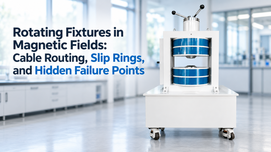
Rotating fixtures in magnetic fields are widely used for angle-dependent material measurements, magnetometer calibration, sensor characterization, anisotropy studies, and multi-axis magnetic testing.
At first glance, the mechanical requirement seems simple:
“Rotate the sample from 0° to 360° inside the magnetic field.”
In practice, the rotating stage is often not the difficult part.
The real engineering problems appear around the stage:
- How should sensor and measurement cables move?
- Can the cables tolerate repeated rotation?
- Is a slip ring required?
- Will a slip ring introduce electrical noise or contact resistance?
- Can the motor, bearings, fasteners, or encoder disturb the magnetic field?
- Will cable torque shift the sample angle?
- Can the full assembly rotate without colliding with the magnet poles or Helmholtz coil frame?
For precision magnetic experiments, the rotating fixture must therefore be treated as part of the measurement system—not as a simple mechanical accessory.
1. Why Rotating Fixtures Become a Magnetic Measurement Problem
A magnetic rotation experiment normally combines several subsystems:
- Magnetic field source
- Sample or device under test
- Rotating stage or goniometer
- Position encoder
- Electrical measurement cables
- Sensor cables
- Motor and motor driver
- Temperature or optical connections
- DAQ or control software
Each subsystem may work perfectly by itself.
Problems appear when they are integrated.
For example, a stage may provide excellent angular resolution on the bench, but once cables are attached, cable torsion can apply a restoring torque to the fixture. A slip ring may solve unlimited rotation mechanically, but introduce additional contact noise into a sensitive electrical measurement.
This is why fixture architecture should be considered before the magnet system is finalized.
2. First Question: Do You Actually Need Mechanical Rotation?
Before designing a rotating fixture, ask whether the experiment requires the DUT to rotate physically.
Option A — Rotate the DUT
The magnetic field remains fixed while the sample or sensor rotates.
This is useful when the experiment specifically needs to measure orientation-dependent behavior relative to:
- Gravity
- Mechanical axes
- Optical geometry
- Sample crystallographic direction
- External instrumentation
Typical applications include:
- Angular magnetoresistance measurements
- Magnetic anisotropy characterization
- Hall or transport measurements
- Magnetometer calibration
- Magnetic material orientation studies
Option B — Keep the DUT Fixed and Rotate the Magnetic Field
A 3-axis Helmholtz coil can generate different X, Y, and Z field components while the DUT remains mechanically stationary.
By changing the current in each axis, the resultant magnetic field vector can be rotated electronically.
This architecture can eliminate many mechanical problems:
- No rotating sensor cable
- No slip ring
- No cable winding
- Reduced mechanical backlash
- Easier automation
- Less fixture-induced vibration
For some magnetometer and sensor calibration applications, electronically rotating the field is therefore cleaner than physically rotating the DUT.
However, these two architectures are not always equivalent. If the experiment depends on physical sample orientation, optical geometry, gravity, mechanical loading, or another fixed laboratory reference, mechanical rotation may still be necessary.
3. Cable Routing: The First Hidden Failure Point
Cable routing is often treated as a detail that can be solved after the stage is installed.
That is a mistake.
Limited-Angle Rotation
If the experiment only requires motion such as:
- ±45°
- ±90°
- ±180°
a properly designed flexible cable loop may be preferable to a slip ring.
The cable should have enough service length to move without becoming tight, but not so much that it enters the magnetic gap or interferes with the fixture.
Important design points include:
- Minimum bend radius
- Strain relief near connectors
- Cable torsion
- Repeated flexing life
- Clearance throughout the full angular range
- Separation between power and low-level signal cables
NASA workmanship guidance for wiring and harnesses specifically emphasizes strain relief, proper support, prevention of excessive flexing, and protection against abrasion at sharp edges. These principles become especially important when a cable is repeatedly moved by a rotating fixture.
Cable Torque Can Become an Angle Error
A cable is also a mechanical spring.
When it twists, it generates torque.
For a large industrial rotary stage, this may be insignificant. For a small precision sample holder, however, cable torque can contribute to:
- Angular offset
- Backlash-like behavior
- Different positions when approaching from opposite directions
- Poor repeatability near small angle steps
This becomes particularly relevant when customers expect precise angular scans but mount several relatively stiff cables on a lightweight sample holder.
The electrical connection is therefore part of the mechanical error budget.
4. When Does a Slip Ring Become Necessary?
A slip ring provides electrical connections between stationary and rotating structures.
It becomes attractive when the system requires:
- Continuous 360° rotation
- Multiple revolutions
- Automated repetitive scans
- Long-duration rotation
- Several electrical connections to a rotating DUT
Instead of allowing the cables themselves to twist, electrical circuits pass through rotating contacts.
That solves one problem—but creates several new design questions.
5. Slip Rings Are Not Electrically Invisible
A common procurement mistake is to specify a slip ring only by:
- Number of channels
- Maximum current
- Maximum voltage
- Shaft diameter
For measurement systems, that is not enough.
Contact Resistance
A slip ring contains sliding electrical contacts.
Those contacts are not ideal zero-resistance connections, and their behavior can change during rotation.
For ordinary power lines, this may be acceptable.
For sensitive measurements, variations in contact resistance can matter significantly.
Electrical Noise
Slip-ring contacts can also introduce electrical noise.
IEEE research on slip-ring and brush contacts has specifically evaluated electrical noise together with friction and wear, demonstrating that the rotating electrical interface itself can become a measurable noise source.
This is especially important for:
- Low-voltage Hall signals
- Bridge sensors
- Resistance measurements
- Thermocouples
- Analog magnetometers
- Low-level current measurements
- Precision sensor calibration
A slip ring that works perfectly for motor power may therefore be inappropriate for a microvolt-level measurement channel.
6. Do Not Route Every Signal Through the Same Slip Ring
The phrase “we need a 12-channel slip ring” does not contain enough information for engineering selection.
The signal types matter.
Typical Circuits May Include
- Motor power
- Encoder signals
- Hall sensor output
- Thermocouple signals
- Four-wire resistance measurement
- Analog voltage
- Digital communication
- Trigger lines
- Ground or shielding connections
These signals have very different requirements.
Motor current can generate switching noise and electromagnetic interference. Low-level analog signals may require much better shielding and isolation.
Whenever possible, high-current and sensitive signal paths should therefore be considered separately rather than treated as identical slip-ring channels.
7. Magnetic Compatibility Is Often More Important Than Mechanical Compatibility
A rotating fixture can fit perfectly inside a magnetic system and still ruin the experiment.
The reason is magnetic material.
Components close to the measurement region may include:
- Steel screws
- Bearings
- Motor housings
- Gearboxes
- Connectors
- Slip-ring housings
- Position sensors
- Cable shields
- Structural brackets
Some components may become magnetized or distort the local field.
This can cause:
- Field asymmetry
- Position-dependent background signals
- Calibration errors
- Hysteresis between scans
- Apparent sample signals that are actually fixture signals
For low-field calibration work, magnetic cleanliness can be particularly important because the fixture-generated disturbance may become comparable with the field being measured.
“Non-magnetic fixture” should therefore not mean only that the main sample holder is aluminum.
The complete rotating assembly should be reviewed.
8. Motors and Encoders Can Also Disturb the Experiment
Motorized rotation simplifies automation, but the motor itself is an electromagnetic device.
Depending on the system geometry, a stepper motor, servo motor, brake, or magnetic encoder located too close to the test region may influence the magnetic environment.
Several approaches can reduce the risk:
- Increase the distance between the motor and homogeneous field region
- Use a mechanical shaft to locate the motor farther away
- Evaluate non-magnetic structural components
- Select encoder technology appropriate for the field environment
- Verify background field with the complete fixture installed
- Perform measurements with the motor powered and unpowered
The important point is simple:
A fixture should be validated in its installed configuration—not only as an isolated mechanical stage.
9. Electromagnets Create a Different Mechanical Constraint
Rotating fixtures inside electromagnets face another limitation: pole-gap geometry.
The available working space may be defined by:
- Pole diameter
- Pole gap
- Sample holder width
- Rotation radius
- Cable exit direction
- Optical access
- Probe access
A sample may fit comfortably when positioned at 0°, but collide with a pole face when rotated to 60° or 90°.
Check the Full Rotation Envelope
The correct mechanical question is not:
“Does the sample fit in the gap?”
It is:
“Does the complete rotating envelope—including holder, connectors, cables, probes, and fasteners—fit throughout the required angular range?”
This distinction prevents many integration problems.
10. 3-Axis Helmholtz Coils Offer More Working Space—but Different Risks
For many calibration applications, a 3-axis Helmholtz coil provides a larger and more open working volume than a conventional electromagnet.
That can make integration easier for:
- Turntables
- Multi-axis gimbals
- Magnetometers
- IMUs
- Navigation sensors
- Larger DUT fixtures
However, the DUT and fixture still need to remain inside the specified homogeneous field region.
A mechanically convenient mounting point is not automatically the correct magnetic measurement position.
The rotation axis, DUT sensing point, and magnetic field center should therefore be defined relative to one another.
11. The Most Common Hidden Failure Points
When reviewing a rotating magnetic fixture, we recommend checking more than the stage specifications.
Mechanical
- Cable becomes tight near the end of travel
- Connector hits magnet pole or coil frame
- Cable torque changes angular repeatability
- Gear backlash affects bidirectional scans
- Fixture flexes under cable load
- Rotation center does not coincide with DUT sensing center
Electrical
- Slip-ring resistance changes during rotation
- Motor noise couples into measurement channels
- Shielding is interrupted at the rotary interface
- Ground loops appear after integration
- Sensitive and power circuits share inappropriate routing
Magnetic
- Steel fasteners disturb the local field
- Motor magnets are too close to the DUT
- Bearings or brackets become magnetized
- Slip-ring materials introduce field distortion
- Fixture position changes the magnetic background
Control
- Stage angle and magnetic field data are not synchronized
- DAQ records before the stage settles
- Cable tension causes actual angle to differ from commanded angle
- Rotation direction changes measurement repeatability
These problems are rarely visible in a product datasheet.
They appear during real experiments.
12. What to Specify Before Requesting a Rotating Magnetic System
A useful technical request should include:
- Required magnetic field range
- Electromagnet or Helmholtz coil preference
- Required homogeneous volume
- DUT dimensions and weight
- Rotation axis
- Angular range
- Required angular resolution
- Required repeatability
- Continuous or limited rotation
- Manual or motorized rotation
- Number and type of electrical connections
- Lowest expected measurement signal
- Optical access requirements
- Temperature sensor connections
- Vacuum or cryogenic interfaces, if applicable
- Required DAQ, PLC, or software synchronization
A photograph or dimensional drawing of the intended DUT assembly is often more useful than several pages of generic specifications.
13. How Cryomagtech Approaches Rotating Magnetic Field Fixtures
For angle scanning, magnetic sensor calibration, material testing, and orientation-dependent measurements, the magnetic field source and mechanical fixture should be considered as one integrated architecture.
Depending on the application, the better solution may be:
- Fixed field + rotating DUT
- 3-axis magnetic field + fixed DUT
- Electromagnet + single-axis rotating fixture
- 3-axis Helmholtz coil + multi-axis sensor fixture
- Custom magnetic system with synchronized motion and field control
Cryomagtech supplies Electromagnet and 3-Axis Helmholtz Coil systems for laboratory magnetic field generation and can evaluate the magnetic working space together with fixture, DUT, access, and control requirements.
👉 Product link placeholder: Cryomagtech 3-Axis Helmholtz Coil & Electromagnet Systems
For rotating experiments, the best system is not necessarily the one with the highest field or the most precise stage.
It is the one in which the magnetic, mechanical, electrical, and control architectures still work together after everything has been installed.
References
- IEEE Xplore — Friction, Wear, and Noise of Slip Ring and Brush Contacts for Synchronous Satellite Use
Relevant to slip-ring contact noise, friction, wear, and rotating electrical interfaces.
IEEE source - NASA — Workmanship Standard for Crimping, Interconnecting Cables, Harnesses, and Wiring (NASA-STD-8739.4A)
Relevant to strain relief, cable support, excessive flexing, and abrasion protection.
NASA standard PDF
Key Takeaways
- A rotating stage should be treated as part of the magnetic measurement system.
- Limited-angle rotation can often use carefully managed flexible cables instead of slip rings.
- Continuous rotation may require slip rings, but contact resistance and electrical noise must be considered.
- Cable torque can create real angular and repeatability errors.
- Motors, bearings, fasteners, and slip-ring components can disturb the magnetic field.
- 3-axis Helmholtz coils can sometimes eliminate mechanical DUT rotation entirely by rotating the magnetic field vector electronically.
- Electromagnet fixtures must be checked against the complete rotational envelope, not only the static sample dimensions.
- The most reliable design considers magnetic field, mechanics, cabling, signal integrity, and automation together.