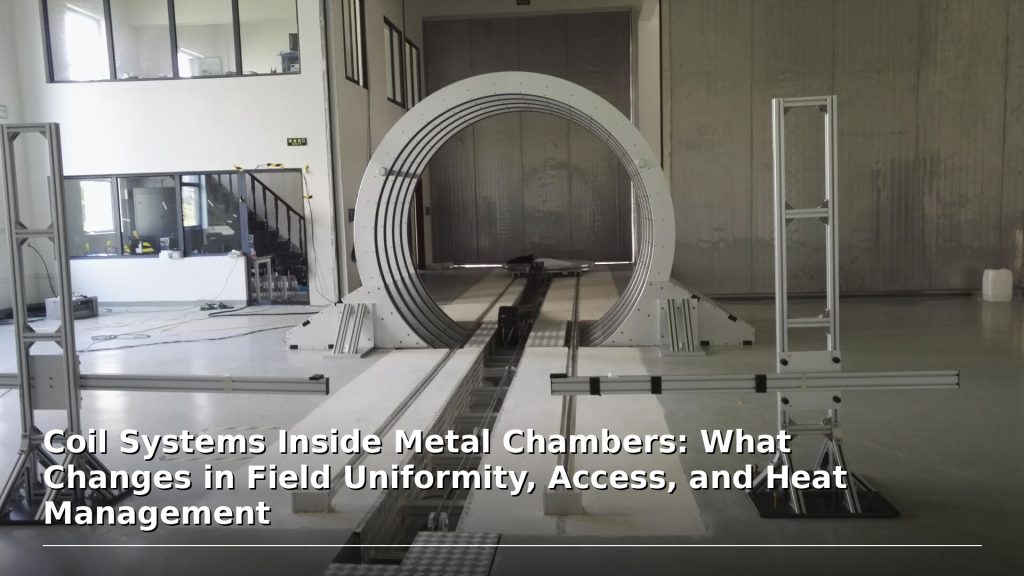
Installing a coil system inside a metal chamber sounds simple at first:
“We already have a chamber. Can we put a Helmholtz coil inside it?”
“We need a magnetic field inside this enclosure.”
“The sample is inside a metal test chamber. Can you design a coil around it?”
“We only need a small field, so it should be easy, right?”
Not always.
For Helmholtz coils, 3-axis coil systems, magnetic field calibration setups, and special environment applications, a metal chamber is not just a passive container. It can affect magnetic field uniformity, access, wiring, heat removal, calibration, and even the basic feasibility of the system.
This article explains what changes when a coil system must work inside or around a metal chamber.
1. Why Metal Chambers Matter in Coil System Design
A coil system is normally designed around open space, defined geometry, and predictable field distribution.
A metal chamber changes that environment.
Depending on material, thickness, shape, openings, distance from the coil, and field type, the chamber may affect:
- Magnetic field distribution
- Field uniformity
- Field amplitude
- Eddy currents
- Heating
- Cable routing
- Cooling path
- Mechanical access
- Sensor placement
- Calibration method
- Acceptance testing
This is especially important for:
- Helmholtz coil systems
- 3-axis magnetic field systems
- Magnetometer calibration chambers
- Sensor test chambers
- Environmental test chambers
- Vacuum chambers
- Metal wind tunnels
- Shielded enclosures
- Industrial test fixtures
A coil that works well in open air may not behave the same way inside a metal chamber.
2. Field Uniformity Can Change
Helmholtz coils are commonly used to produce a region of nearly uniform magnetic field. A standard Helmholtz coil consists of two matched coils on the same axis carrying equal current in the same direction. (wikipedia.org)
However, that “nearly uniform” field assumes a controlled geometry.
When a metal chamber is placed near the coil or around the field region, it may disturb the field.
This can happen because of:
- Ferromagnetic material pulling magnetic flux
- Conductive material generating eddy currents under time-varying fields
- Chamber walls being too close to the coil
- Ports and openings breaking symmetry
- Bolts, frames, and brackets introducing local distortion
- Large metal panels changing boundary conditions
The result may be a field that is no longer as uniform as expected.
For calibration or sensor testing, this matters. A field that is uniform in simulation without the chamber may not be uniform after installation inside the real chamber.
3. Chamber Material Is Critical
Not all metal chambers behave the same way.
Ferromagnetic materials
Steel or other ferromagnetic materials can strongly affect magnetic field distribution. They may attract, guide, or distort magnetic flux.
This can be useful in magnetic shielding, but problematic if the goal is a clean uniform field in a test volume.
Non-magnetic conductive materials
Aluminum, copper, and some stainless steels may not strongly attract magnetic flux under DC conditions, but they can still create issues in AC or changing fields.
Time-varying magnetic fields can induce eddy currents in conductive structures. These induced currents may oppose the applied magnetic field and change the field amplitude, phase, and uniformity.
Stainless steel
Some stainless steels are mostly non-magnetic, while others may show magnetic behavior depending on grade, processing, welding, or mechanical work.
So the supplier should not simply be told “it is stainless steel.”
The grade, thickness, and location matter.
4. DC Fields and AC Fields Behave Differently
A metal chamber may affect DC and AC magnetic fields differently.
DC or static fields
For DC fields, ferromagnetic materials are the main concern. A steel chamber can redirect flux and distort the intended field.
Non-magnetic conductive materials may have less effect once the field is stable, although transient behavior during current ramping can still matter.
AC or time-varying fields
For AC fields, conductive metals become more important because of eddy currents.
Eddy currents are loops of electric current induced inside conductors by changing magnetic fields. These currents create their own magnetic fields and can oppose the original field change. (wikipedia.org)
This means an AC coil inside a metal chamber may experience:
- Reduced field amplitude
- Phase shift
- Extra heating in metal walls
- Frequency-dependent behavior
- Distorted field distribution
- Higher power demand
- Lower usable field at the sample position
For AC coil systems, chamber material and frequency cannot be ignored.
5. Openings, Ports, and Windows Break Symmetry
Real chambers are rarely perfect cylinders or boxes.
They often include:
- Cable ports
- Vacuum flanges
- Optical windows
- Feedthroughs
- Doors
- Hinges
- Handles
- Mounting rails
- Sensor ports
- Cooling connections
- Access panels
These features can affect field symmetry.
For example, a large metal door on one side of a chamber may distort the field differently from the opposite side. A flange near the sample region may introduce local distortion. A cable feedthrough may limit where the coil can be placed.
When field uniformity matters, chamber geometry should be included early in the design review.
A simple external dimension is not enough.
6. Access Becomes an Engineering Constraint
Inside a metal chamber, space is usually limited.
The coil system must share space with:
- DUT or sample
- Sample holder
- Sensor fixture
- Thermal stage
- Vacuum hardware
- Optical path
- Cables
- Cooling tubes
- Motion mechanism
- Measurement probes
- Chamber walls and ports
This can affect:
- Coil diameter
- Coil spacing
- Axis arrangement
- Number of coil layers
- Wire routing
- Connector location
- Field center position
- Sample loading method
- Maintenance access
For 3-axis coil systems, access becomes even harder because multiple coil sets must fit around the same working volume.
A compact design may be possible, but smaller coils often mean higher current, tighter thermal limits, smaller uniform region, or more difficult mechanical integration.
There is no free geometry.
7. Heat Management Becomes More Difficult
A coil inside a metal chamber generates heat.
That heat must go somewhere.
In open air, heat can be removed by natural convection, forced air, or water cooling. Inside a chamber, heat removal may be limited by:
- Restricted airflow
- Poor ventilation
- Chamber sealing
- Vacuum conditions
- Small internal volume
- Limited fan use
- Heat-sensitive samples
- Temperature-controlled environment
- Cable and feedthrough limits
If the chamber is sealed or poorly ventilated, coil temperature may rise faster than expected.
This can cause:
- Resistance increase
- Field drift
- Insulation stress
- Shorter duty cycle
- Thermal expansion
- Damage to nearby components
- Reduced measurement stability
For continuous operation or higher fields, water cooling or external heat extraction may be required.
8. Vacuum Chambers Add Another Layer of Difficulty
If the coil is inside a vacuum chamber, the challenge becomes much harder.
In vacuum, there is little or no convective cooling.
Heat removal depends mainly on:
- Conduction through supports
- Radiation
- Water-cooled structures
- Thermal straps
- Feedthrough design
- Coil insulation compatibility
- Vacuum-compatible materials
Standard coil insulation, adhesives, plastics, fans, and connectors may not be suitable for vacuum use.
Vacuum applications may require:
- Low-outgassing materials
- Vacuum-compatible wiring
- Special feedthroughs
- Careful thermal design
- Bake-out compatibility if required
- Separate acceptance criteria
A coil that is safe in air may overheat in vacuum if the heat path is not designed correctly.
9. Metal Chambers Can Change Calibration and Acceptance
When a coil system is installed inside a chamber, factory testing and final performance may not be identical.
Factory tests may be done in open conditions, while the final installation may include:
- Chamber walls
- Ports
- Steel frames
- Local magnetic materials
- Customer fixtures
- Different cable routing
- Different grounding
- Different cooling conditions
- Different sensor positions
This means the acceptance plan should clearly separate:
- What can be verified before shipment
- What depends on the customer’s chamber
- What must be verified after installation
- Whether field mapping should include the chamber
- Whether simulation includes chamber geometry
- Whether the chamber material is known
For serious projects, a field map without the chamber may be useful, but not final proof of installed performance.
10. Simulation May Be Necessary
If the metal chamber is close to the coil or sample region, simulation may be needed.
Simulation can help evaluate:
- Field distortion from chamber walls
- Effect of ports and openings
- Coil position sensitivity
- Working volume
- Uniformity changes
- AC eddy current effects
- Heat and cooling constraints
- Whether a larger or different coil geometry is required
But simulation only works when the input is real.
The supplier may need:
- Chamber dimensions
- Wall thickness
- Material grade
- Port locations
- Sample position
- Required field direction
- Required field range
- DC or AC operation
- Frequency range
- Available space
- Cooling constraints
- Access requirements
If the customer cannot provide chamber drawings or material information, simulation becomes much less reliable.
11. Field Mapping Inside the Chamber May Be Required
For calibration-related applications, field mapping inside the actual chamber is often the safest way to verify performance.
Field mapping may check:
- Center field
- Uniformity region
- Field direction
- Field gradient
- Axis orthogonality
- Field-current relationship
- Background field
- Effect of chamber doors or ports
- Repeatability after opening and closing
NIST’s magnetic sensing and metrology program describes capabilities for magnetic sensor performance measurement and synthetic field environments for testing sensor performance in application environments, which highlights why controlled and verified magnetic field environments matter for sensor-related work. (nist.gov)
For customers using coils inside chambers for magnetometer, IMU, or sensor calibration, the final chamber environment may be part of the calibration system.
12. Cable and Feedthrough Design Matters
A chamber-based coil system needs a practical way to bring power and signals in and out.
This may involve:
- Cable glands
- Vacuum feedthroughs
- Shielded connectors
- High-current feedthroughs
- Waterproof or sealed connectors
- Temperature-rated cables
- Strain relief
- Grounding design
- Connector labeling
- Service access
For high-current coil systems, cable routing affects:
- Voltage drop
- Heating
- Noise
- Safety
- Mechanical stress
- Maintenance
For sensitive sensors, signal cables should be separated from high-current coil cables when possible.
Inside a small chamber, this separation is not always easy.
That is why cable routing should be considered early, not after the coil is already built.
13. Magnetic Cleanliness Inside the Chamber
For low-field and calibration applications, even small magnetic parts can matter.
Potential problems include:
- Steel screws
- Magnetic bearings
- Tool marks or clamps
- Motor shafts
- Spring clips
- Magnetic connectors
- Work-hardened stainless steel parts
- Nearby speakers or motors
- Magnetized tools
If the goal is geomagnetic simulation, sensor calibration, or low-field compensation, these small items can create local field errors.
A metal chamber may look clean mechanically but still be magnetically dirty.
For demanding applications, non-magnetic material selection and demagnetization procedures may be needed.
14. Questions to Answer Before Requesting a Coil System
Before requesting a coil system for a metal chamber, prepare the following information:
- Is the coil inside the chamber or outside the chamber?
- What is the chamber material?
- Is it ferromagnetic, non-magnetic stainless steel, aluminum, or another alloy?
- What is the wall thickness?
- What are the internal dimensions?
- Where is the sample or DUT located?
- What field strength is required?
- Is the field DC or AC?
- If AC, what frequency and waveform are needed?
- What uniformity volume is required?
- What access ports and windows exist?
- Are there metal fixtures near the field region?
- Is cooling available?
- Is the chamber sealed, ventilated, or under vacuum?
- Are drawings or photos available?
- Is final field mapping required inside the chamber?
These answers can save weeks of back-and-forth.
15. Common Mistakes in Chamber-Based Coil Projects
Common mistakes include:
- Treating the chamber as empty space
- Ignoring chamber material
- Ignoring wall thickness
- Designing the coil without port locations
- Assuming open-air field uniformity still applies
- Forgetting eddy currents in AC applications
- Placing magnetic screws near the sample
- Ignoring cooling in sealed chambers
- Assuming factory field mapping applies after installation
- Providing no chamber drawing
- Defining field strength but not working volume
- Asking for a compact coil without accepting thermal or uniformity trade-offs
Most failures in these projects are not caused by the coil alone.
They come from ignoring the chamber as part of the system.
16. How Cryomagtech Supports Coil Systems for Metal Chambers
Cryomagtech supplies Helmholtz coil systems, 3-axis magnetic field systems, electromagnets, excitation power supplies, and custom coil configurations for research and industrial laboratories.
For chamber-based coil projects, we can help customers evaluate:
- Coil placement inside or outside the chamber
- Field uniformity and working volume
- Chamber material influence
- DC vs AC field feasibility
- Heat management and duty cycle
- Cable and feedthrough requirements
- Field mapping and acceptance conditions
- Whether simulation is needed before final design
Our goal is not only to provide a coil.
Our goal is to help customers understand how the chamber changes the magnetic, mechanical, thermal, and acceptance conditions of the complete system.
For chamber-based applications, the coil and the chamber must be treated as one integrated environment.
References
- Wikipedia – Helmholtz Coil
A Helmholtz coil is used to produce a region of nearly uniform magnetic field, typically using two matched coils carrying equal current in the same direction.
https://en.wikipedia.org/wiki/Helmholtz_coil - Wikipedia – Eddy Current
Eddy currents are induced loops of electric current inside conductors caused by changing magnetic fields; they create magnetic fields that can oppose the original field change.
https://en.wikipedia.org/wiki/Eddy_current - NIST – Magnetic Sensing and Metrology
NIST describes magnetic sensor measurement and synthetic field environments for accurately testing sensor performance in application environments.
https://www.nist.gov/programs-projects/magnetic-sensing-and-metrology
Key Takeaways
- A metal chamber can change field uniformity, field amplitude, access, heating, and acceptance conditions.
- Ferromagnetic materials can distort magnetic flux, while conductive metals can create eddy current effects under changing fields.
- DC and AC coil applications behave differently inside metal chambers.
- Chamber ports, doors, windows, and feedthroughs can break field symmetry.
- Heat management is harder in sealed, compact, or vacuum chambers.
- Factory test results may not fully represent final installed performance inside the customer’s chamber.
- Chamber drawings, material information, and sample position are essential for a meaningful coil system proposal.
A coil system inside a metal chamber is not just a coil placed in a box.
It is an integrated magnetic, mechanical, thermal, and measurement environment.