Generating an AC magnetic field is easy.
Generating a clean, truly sinusoidal AC field is not.
In many laboratory setups, the focus is on:
- Frequency range
- Field amplitude
But experienced users know the real challenge lies in:
👉 field quality
This includes:
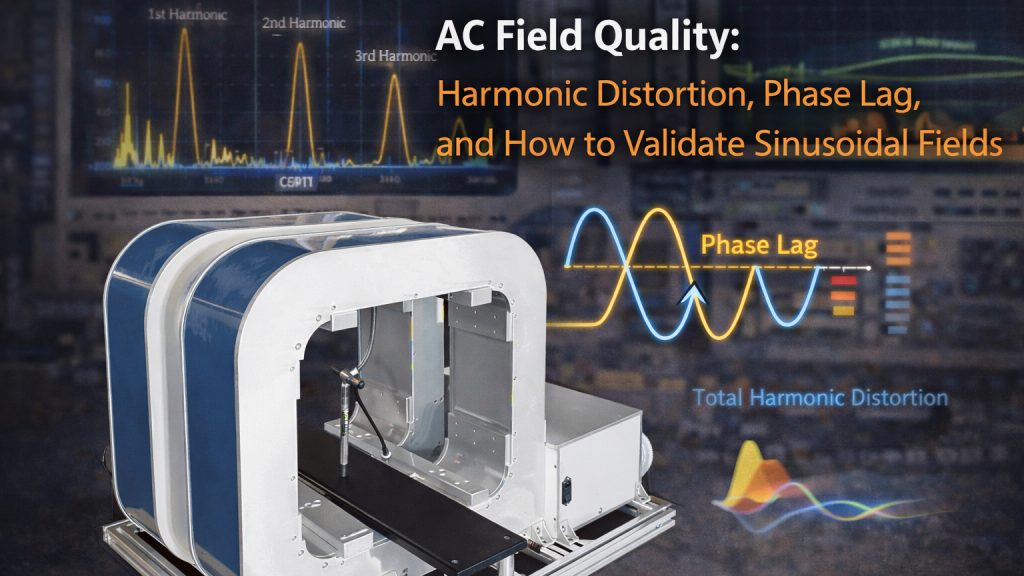
- Harmonic distortion
- Phase lag
- Stability under load
If these are not controlled, your “AC field” may not be sinusoidal at all.
1. What Defines AC Field Quality
An ideal AC magnetic field should be:
- Pure sinusoidal waveform
- Stable amplitude
- Predictable phase relationship
In reality, deviations occur due to:
- Nonlinear components
- Power electronics behavior
- Coil impedance characteristics
According to Wikipedia:
https://en.wikipedia.org/wiki/Harmonic_distortion
Harmonic distortion represents unwanted frequency components added to the fundamental signal, altering waveform purity.
2. Harmonic Distortion: When a Sine Wave Is Not a Sine Wave
What Causes Harmonics
- Nonlinear amplifier response
- Core material effects (if present)
- Power supply switching artifacts
- Saturation behavior at high current
Why It Matters
A distorted waveform leads to:
- Incorrect magnetic excitation
- Measurement artifacts
- Misinterpretation of material properties
In applications such as:
- Magnetic susceptibility
- AC loss measurements
- Lock-in detection
👉 Even small harmonic content can corrupt results.
3. Phase Lag: The Hidden Timing Error
In AC systems, current and magnetic field are not always perfectly aligned.
Sources of Phase Lag
- Coil inductance
- Cable impedance
- Control loop delay
- Measurement system latency
Practical Impact
- Field does not match input signal timing
- Lock-in detection loses accuracy
- Dynamic measurements become unreliable
According to IEEE research on AC systems, phase accuracy is critical in high-precision measurement environments.
4. Coil and Drive Interaction: The Real System Behavior
A coil is not just a passive element.
It behaves as:
- Resistance (R)
- Inductance (L)
- Parasitic capacitance (C)
Together, they form a frequency-dependent system.
What This Means
- At low frequency → mostly resistive
- At higher frequency → inductive effects dominate
- Near resonance → complex behavior
Result:
👉 The output field waveform depends on both the coil and the driver
Not just one of them.
5. Why “AC Capability” Specs Are Misleading
Many systems claim:
- “Supports AC operation”
- “Up to XX Hz frequency”
But do not specify:
- Harmonic distortion (THD)
- Phase accuracy
- Stability under load
Typical Reality
- Signal looks sinusoidal at no load
- Distorts significantly when connected to real coils
This is where most systems fail in actual experiments.
6. How to Validate AC Field Quality
If you cannot measure it, you cannot trust it.
Recommended Validation Methods
1. Oscilloscope Measurement
- Measure current waveform directly
- Check for distortion and asymmetry
2. Hall Probe or Pickup Coil
- Measure actual magnetic field waveform
- Compare with input signal
3. FFT Analysis
- Identify harmonic components
- Quantify Total Harmonic Distortion (THD)
4. Phase Measurement
- Compare reference signal vs field response
- Determine phase lag across frequency range
7. Calibration: Not Optional for Precision Work
Calibration ensures that:
- Measured field matches expected waveform
- Phase relationships are understood
- System response is predictable
Without Calibration
- Results may be repeatable but wrong
- Systematic errors remain hidden
With Calibration
- Data becomes physically meaningful
- Experimental confidence increases
8. How Cryomagtech Supports Clean AC Field Generation
At Cryomagtech, AC field quality is treated as a system-level challenge.
We consider:
- Coil impedance across frequency
- Driver linearity and control strategy
- Harmonic suppression
- Phase stability under load
👉 Product link placeholder: Cryomagtech AC Magnet Field Systems & Drive Solutions
Instead of specifying only frequency and amplitude,
we focus on:
- Waveform integrity
- Repeatable dynamic performance
- Measurement-grade field quality
Because in AC applications:
👉 a distorted sine wave is not just imperfect—it is misleading.
References
- Wikipedia – Harmonic Distortion
https://en.wikipedia.org/wiki/Harmonic_distortion - IEEE – AC signal integrity and distortion analysis
https://ieeexplore.ieee.org/
Key Takeaways
- AC field quality depends on waveform purity, not just amplitude
- Harmonic distortion introduces measurement errors
- Phase lag affects timing-sensitive experiments
- Coil and driver must be considered as a coupled system
- Validation requires measurement, not assumptions
- Calibration is essential for reliable results
If your experiment depends on AC magnetic fields,
what matters is not whether you can generate AC—
👉 but whether that AC is actually sinusoidal.