
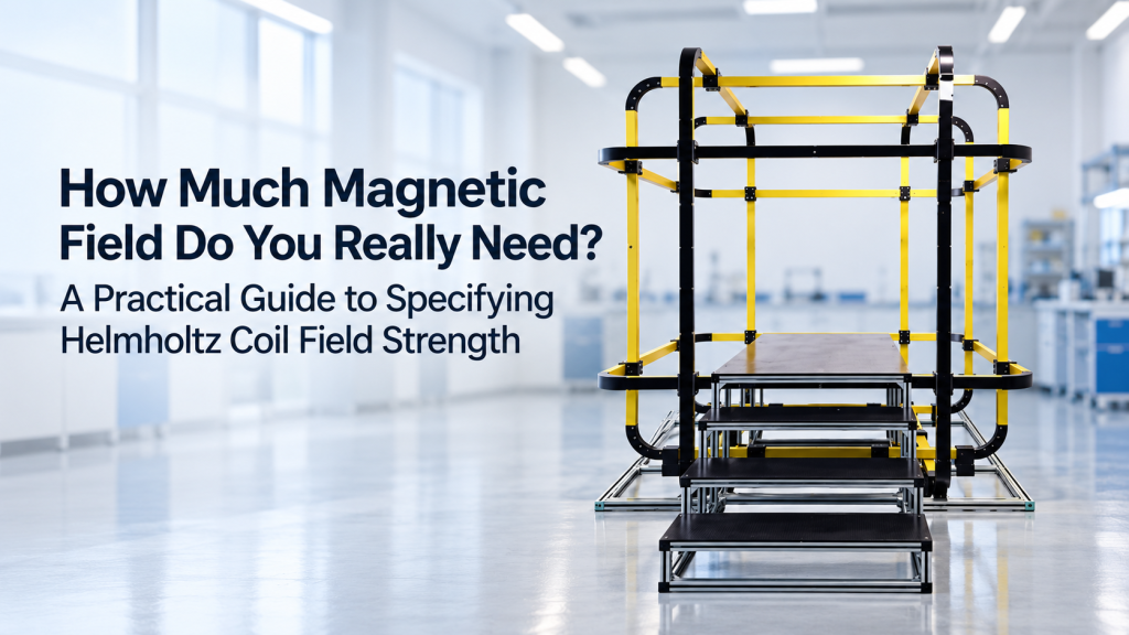
“How much magnetic field do you need?”
For many buyers, this is one of the hardest questions in a Helmholtz coil RFQ.
The first answer is often:
“As high as possible.”
Or:
“Our experiment probably needs 10 mT, so let us specify 50 mT just to be safe.”
That sounds cautious. In practice, it can push the entire Helmholtz coil system in the wrong direction.
Higher field strength may require:
- More ampere-turns
- Higher-current power supplies
- Larger conductor cross-sections
- More electrical power
- More cooling
- Higher system weight
- Higher cost
- Reduced AC bandwidth
- Greater thermal drift
- Different coil geometry
At the same time, a larger working volume usually requires larger coils—and larger coils generally need more current or turns to generate the same magnetic field.
So the correct question is not:
“What is the highest field we can afford?”
It is:
“What magnetic field does the experiment actually require, under what conditions, and how much engineering margin is genuinely useful?”
This guide explains how to answer that question before specifying a Helmholtz coil system.
1. Start with the Experiment, Not the Coil
Before selecting a Helmholtz coil field strength, define what the magnetic field is supposed to do.
Different experiments can require completely different field ranges.
Typical applications include:
- Magnetometer calibration
- IMU and electronic compass testing
- Hall sensor characterization
- Geomagnetic field simulation
- Earth-field cancellation
- Magnetic sensor testing
- Magnetic immunity testing
- Low-field material experiments
- Bias-field generation
- Vector magnetic field simulation
A system designed for geomagnetic compensation may operate primarily in the tens of microtesla range.
A system intended for magnetic sensor characterization may require hundreds of microtesla or several millitesla.
Another application may need tens of millitesla or more.
These should not automatically be treated as the same Helmholtz coil.
2. Put the Field Requirement in the Correct Unit First
One surprisingly useful step is to normalize all field requirements into one unit.
Common units are:
- Tesla (T)
- Millitesla (mT)
- Microtesla (µT)
- Gauss (G)
Useful conversions:
- 1 T = 1,000 mT
- 1 mT = 1,000 µT
- 1 T = 10,000 G
- 1 G = 100 µT
- 1 mT = 10 G
So:
50 µT = 0.05 mT = 0.5 G
while:
50 mT = 500 G
Those values differ by a factor of 1,000.
That is not a small specification difference.
It can define a completely different power, conductor, cooling, and cost architecture.
3. Use the Earth’s Magnetic Field as a Useful Reality Check
For magnetometer, compass, IMU, navigation, and geomagnetic simulation projects, the Earth’s magnetic field provides a useful reference scale.
NOAA states that the total intensity of Earth’s magnetic field is roughly 25,000–65,000 nT, equivalent to approximately 25–65 µT or 0.25–0.65 G, depending on location. NCEI
That gives buyers an immediate sanity check.
Example: electronic compass testing
If the primary goal is:
- Simulating normal geomagnetic conditions
- Testing heading response
- Measuring low-field sensor offsets
- Cancelling local Earth field
then a system designed for several tesla—or even hundreds of millitesla—would usually be solving a completely different problem.
A range such as:
- ±50 µT
- ±100 µT
- ±200 µT
may already provide meaningful testing headroom depending on the DUT and test method.
The correct value should come from the sensor specification and test protocol, not from a desire to maximize the headline magnetic field.
4. Why Helmholtz Coil Field Strength Depends on Coil Size
For an ideal circular Helmholtz coil pair, the magnetic field at the center is:
B = (4/5)³ᐟ² × μ₀NI / R
where:
- B = magnetic field
- μ₀ = permeability of free space
- N = number of turns per coil
- I = current
- R = coil radius
For the classic Helmholtz geometry, the two identical coils are separated by a distance equal to their radius. This arrangement suppresses the second-order spatial variation of the field around the center, creating the characteristic uniform region. Wikipedia
The practical engineering relationship is:
B ∝ NI / R
That simple relationship explains a large part of Helmholtz coil design.
Higher field requires more ampere-turns
To increase B, you generally need:
- More current I
- More turns N
- Or both
Larger coils work against field strength
If R increases while everything else remains unchanged:
The center field decreases.
So when a customer asks for both:
- A very large open working volume
and:
- A very high magnetic field
the project becomes substantially more demanding.
5. Working Volume and Field Strength Compete with Each Other
This is one of the most important procurement relationships to understand.
Suppose two buyers both need 10 mT.
Buyer A
DUT size:
20 × 20 × 10 mm
Buyer B
DUT size:
500 × 500 × 500 mm
These are not remotely equivalent coil requirements.
The second system needs a dramatically larger coil structure.
As coil dimensions increase, maintaining the same field generally requires more ampere-turns. That can increase:
- Copper quantity
- Electrical resistance
- Supply voltage
- Supply current
- Power
- Heat
- Structural requirements
- Overall cost
Therefore, never specify Helmholtz coil field strength without also specifying the usable working volume.
A requirement such as:
“50 mT Helmholtz coil required”
is incomplete.
A much better requirement is:
“50 mT within a 100 × 100 × 100 mm usable region.”
Now engineering can actually begin.
6. Do Not Confuse Coil Diameter with Uniform Field Volume
A 500 mm coil does not mean you have a 500 mm region of high-uniformity magnetic field.
The useful homogeneous region is only part of the physical coil aperture.
The tighter the required uniformity, the smaller the useful region generally becomes.
For example, these are very different specifications:
- ±5% over 200 mm
- ±1% over 200 mm
- ±0.1% over 200 mm
- ±0.01% over 200 mm
A buyer asking for “large coils” should therefore answer two separate questions:
Physical access requirement
How large must the opening be to accommodate:
- DUT
- Fixture
- Cables
- Probe
- Rotation platform
- Thermal chamber
Magnetic uniformity requirement
Over what volume must the field meet the specified uniformity?
Those two dimensions should not be assumed to be identical.
7. Higher Field Is Not Free: Current Is Only the Beginning
It is tempting to think:
“If 5 A gives us 5 mT, we can simply use 50 A to get 50 mT.”
The physics may be approximately linear within the appropriate operating range.
The engineering is not.
Increasing current affects several things at once.
Resistive heating follows I²R
Coil heating approximately follows:
P = I²R
If the coil resistance remained constant, doubling current would produce roughly four times the resistive heating.
Increasing current from:
5 A → 10 A
does not simply double the thermal challenge.
It can approximately quadruple the I²R heating for the same resistance.
That affects:
- Conductor size
- Insulation
- Coil temperature
- Cooling
- Thermal drift
- Continuous duty capability
This is why unnecessary magnetic field margin can become expensive surprisingly quickly.
8. Why “Just Add More Turns” Is Not a Free Solution Either
The Helmholtz equation suggests another possibility:
If more turns increase field, why not simply add many more turns instead of increasing current?
Because turns also have consequences.
More turns mean more conductor length.
That generally increases:
- Resistance
- Inductance
- Coil volume
- Voltage requirement
- Weight
For DC applications, additional turns may sometimes be an efficient engineering choice.
For AC applications, higher inductance can become a serious constraint.
So there is no universal rule saying:
more current is better
or:
more turns are better.
The correct combination depends on:
- Required field
- Coil dimensions
- DC or AC operation
- Frequency
- Duty cycle
- Cooling
- Available power supply
9. DC Field Strength and AC Field Strength Are Not the Same Specification
This is an extremely common RFQ mistake.
A buyer may request:
Magnetic field: ±20 mT
But does that mean:
- ±20 mT DC?
- ±20 mT at 1 Hz?
- ±20 mT at 50 Hz?
- ±20 mT at 1 kHz?
These are completely different engineering conditions.
Why frequency matters
A coil has:
- Resistance
- Inductance
For AC operation, inductive reactance increases with frequency.
Conceptually:
Xₗ = 2πfL
where:
- Xₗ = inductive reactance
- f = frequency
- L = inductance
As frequency rises, the power supply may require increasingly high voltage to maintain the desired current.
So a system capable of:
20 mT DC
does not automatically produce:
20 mT at 1 kHz.
A better AC specification
Instead of:
Field ≥20 mT, AC capable
write:
20 mT peak at 50 Hz
or provide a field-versus-frequency envelope.
For example:
- 20 mT at DC–10 Hz
- 10 mT at 100 Hz
- 2 mT at 1 kHz
if those are the actual experimental requirements.
10. Define the Normal Operating Field Before the Maximum Field
One of the best ways to avoid overspecification is to define two values.
Normal operating field
The range used during most experiments.
Example:
±2 mT
Maximum required field
The highest field genuinely needed for occasional tests.
Example:
±3 mT
Now the supplier understands the duty profile.
That is much more useful than simply requesting:
Maximum field ≥10 mT
when 95% of experiments operate below 2 mT.
11. How Much Safety Margin Should You Add?
Engineering margin is sensible.
Unlimited margin is not.
Suppose your actual test requires:
±5 mT
Possible specifications might be:
- ±5 mT
- ±6 mT
- ±7.5 mT
- ±10 mT
- ±20 mT
Which one is correct?
There is no universal percentage.
The margin should cover real uncertainties such as:
- Future test variation
- Background field compensation
- DUT tolerances
- Calibration range
- Power-supply operating headroom
- Field loss caused by integration constraints
- Expected future applications
A practical approach
Instead of saying:
“Double it for safety.”
ask:
What condition could realistically require more field than our current test maximum?
If there is no credible answer, 100% extra field may simply be unnecessary cost.
For many projects, a moderate engineering margin above the verified operating requirement is more rational than automatically specifying 2×, 5×, or 10× the required field.
12. Separate “Experimental Margin” from “System Headroom”
These are two different ideas.
Experimental margin
The researcher may need:
- 5 mT today
- Possibly 6 mT for future DUTs
So the experiment might justify a 6–7 mT usable range.
Engineering headroom
The coil and power supply may internally be designed so they are not operated continuously at their absolute thermal or electrical limit.
That is the manufacturer’s engineering responsibility.
The buyer does not necessarily need to turn that internal engineering headroom into a much larger published field requirement.
If both buyer and supplier independently add large safety factors, the final system can become severely oversized.
13. Background Magnetic Field Must Be Included in the Calculation
For low-field applications, the ambient magnetic field can be comparable to the field you are trying to generate.
Suppose you want the DUT to experience:
+50 µT along X
but the ambient X component is:
−30 µT
The coil may need to generate approximately:
+80 µT
to reach the desired net field.
Similarly, generating a near-zero magnetic environment requires the system to cancel ambient components.
NOAA describes the Earth’s field using X, Y, Z and other components, and notes that the total intensity varies significantly with geographic location. NCEI
For geomagnetic simulation, therefore define:
- Ambient field
- Required compensated field
- Required simulated field
- Margin for environmental variation
This is more useful than specifying an arbitrary maximum coil field.
14. 3-Axis Systems Need Special Attention to Field Strength
For a 3-axis Helmholtz coil system, “100 µT field” can mean several different things.
Interpretation A
Each axis can independently produce:
±100 µT
Then the maximum possible simultaneous vector magnitude is:
√(100² + 100² + 100²) ≈ 173 µT
if all three axes are driven to maximum together.
Interpretation B
The required resultant vector magnitude is:
100 µT in any direction
That is a different design statement.
Interpretation C
The system must generate:
- X = ±100 µT
- Y = ±100 µT
- Z = ±50 µT
Again, different.
For vector calibration systems, specify per-axis requirements and resultant-field requirements separately.
15. Do All Three Axes Need the Same Maximum Field?
Not necessarily.
Equal-axis specifications look neat on a datasheet, but experiments do not always require them.
For example:
- X: ±5 mT
- Y: ±5 mT
- Z: ±2 mT
may be perfectly valid if the test protocol is asymmetric.
However, equal field capability can simplify:
- Software
- Calibration procedures
- Vector field synthesis
- DUT orientation testing
The decision should come from the application rather than aesthetics.
16. Field Uniformity May Matter More Than Maximum Field
Consider two coil systems:
System A
Maximum field:
20 mT
Uniformity:
±0.1% over the DUT volume
System B
Maximum field:
50 mT
Uniformity:
±5% over the same volume
Which is better?
There is no answer until you know the experiment.
For precision sensor calibration, System A could be far more useful despite having less than half the headline field strength.
A magnetic calibration system should therefore never be evaluated only by maximum field.
At minimum, consider:
- Maximum field
- Uniformity
- Uniform volume
- Stability
- Accuracy
- Repeatability
17. Stability Can Matter More Than Additional Field Range
Suppose your magnetometer calibration uses:
±100 µT
Would you rather have:
System A
Maximum: ±500 µT
Excellent long-term stability
or:
System B
Maximum: ±5 mT
Poor thermal stability during long tests
If your experiment never exceeds ±100 µT, the extra field capability of System B may provide no meaningful benefit.
For long calibration runs, coil heating and current-source stability can directly affect field reproducibility. A larger maximum-field rating is not automatically a better calibration platform.
18. Continuous Field and Short-Duration Field Should Be Specified Separately
Another important distinction is duty cycle.
A coil may be able to generate a certain high field briefly but require reduced current for continuous operation.
For example, a project might need:
- 10 mT continuous
- 20 mT for 30 seconds
- Return to 10 mT afterward
That may allow a very different design from:
20 mT continuously for eight hours.
Always tell the supplier:
- Required continuous field
- Peak field
- Peak duration
- Rest interval
- Daily operating duration
Thermal design follows the real operating profile.
19. Cooling Method Can Change as Field Requirements Increase
Moderate field levels and duty cycles may allow passive or forced-air cooling.
Higher power levels can make water cooling more appropriate.
Cryomagtech’s current Helmholtz coil product architecture includes air-cooled and water-cooled options, with the final configuration depending on field strength, coil size, duty cycle, and thermal requirements. Cryomagtech
This creates an important procurement chain:
Higher field → higher electrical demand → more heat → stronger cooling requirements → more system infrastructure
So an apparently small increase in requested field can sometimes push the project across an engineering threshold.
20. Larger Current Also Means a Larger Power Supply
The coil is only one part of the system.
The required current and voltage determine the excitation electronics.
A stronger field may require:
- Higher-current constant-current supply
- Higher compliance voltage
- Bipolar output
- Larger cables
- More robust connectors
- Higher mains power
- Additional cooling
For multi-axis systems, these requirements can multiply across several channels.
A 3-axis system with three high-power channels can therefore be much more expensive than a low-field 3-axis calibration platform even if the mechanical coil structure looks similar.
21. Do You Need Open-Loop or Closed-Loop Field Control?
Another question affects how much practical field margin is needed.
Open-loop system
The coil field is controlled primarily through current:
Current command → coil → magnetic field
The field can be calculated or characterized using the coil constant.
Closed-loop system
A field probe measures the actual field and provides feedback:
Field target → controller → current source → coil → field probe → feedback
Closed-loop control can be useful where actual magnetic field rather than current is the primary controlled variable.
Cryomagtech’s Helmholtz Coil Systems can integrate the coil set with programmable power electronics, gaussmeter instrumentation, and PC control for field generation and calibration applications. Cryomagtech
Suggested target page: Cryomagtech Helmholtz Coil Systems
22. A Practical Example: Magnetometer Calibration
Suppose a magnetometer will normally measure geomagnetic fields.
The test requirements might be:
- Normal operating region: ±65 µT
- Calibration sweep: ±100 µT
- Offset evaluation: around zero field
- Three-axis vector testing
- DUT size: 50 × 50 × 20 mm
- Continuous operation
- High field stability
Would specifying:
±50 mT
make the system better?
Probably not for this application.
That is 500 times the ±100 µT calibration range.
The higher field could require substantially different power electronics, thermal design, and coil winding without improving the actual geomagnetic calibration.
A better specification would focus on:
- ±100 or ±150 µT usable per-axis range
- Required uniform volume
- Low-field resolution
- Zero-field performance
- Stability
- Background compensation
- Vector accuracy
That is an application-driven specification.
23. Another Example: Hall Sensor Characterization
Now consider a Hall sensor that must be characterized from:
−10 mT to +10 mT
The requirements might be:
- ±10 mT test range
- Bipolar sweep
- 5 mT continuous normal operation
- 10 mT maximum test point
- ±0.5% uniformity over the DUT
- DC to 10 Hz
- Continuous laboratory operation
A reasonable design discussion might consider some additional operating headroom.
But jumping immediately to:
±100 mT
without another application reason could unnecessarily increase:
- Current
- Power
- Cooling
- Coil size optimization pressure
- Power supply cost
The experimental requirement—not the desire for a larger specification number—should control the design.
24. A Third Example: Large DUT, Modest Magnetic Field
Suppose the required magnetic field is only:
1 mT
That sounds easy.
But the DUT measures:
800 × 600 × 500 mm
and the entire DUT must sit within a useful uniform-field region.
Now the dominant engineering problem may not be field strength.
It may be:
- Coil dimensions
- Uniform volume
- Mechanical frame
- Structural rigidity
- Winding quantity
- Power consumption
- Installation space
- Shipping
A “low-field” project can therefore still become a large engineering system.
This is why field strength should never be specified independently from geometry.
25. Cost Does Not Scale Linearly with Magnetic Field
Buyers sometimes assume:
“If 10 mT costs X, then 20 mT should cost approximately 2X.”
That is not necessarily how system design behaves.
There may be thresholds where increasing field requires:
- Thicker conductor
- New winding geometry
- Larger power supply
- Water cooling instead of air cooling
- Higher-capacity chiller
- Different insulation
- Larger electrical cabinet
- Stronger connectors
The cost curve can therefore contain engineering steps rather than a smooth linear increase.
The most economical field specification is usually the one that achieves the experiment with sensible—not arbitrary—headroom.
26. Standard Coil or Customized Helmholtz Coil?
Cryomagtech currently offers single-, dual-, and three-axis Helmholtz coil configurations, including circular, square, high-uniformity, and customized large-coil architectures. Cryomagtech
Standard solutions can be attractive when the requirements fit existing combinations of:
- Coil dimensions
- Field range
- Uniform region
- Number of axes
- Power
- Cooling
Customization becomes more likely when buyers simultaneously require:
- Large DUT
- Large uniform volume
- High field
- Tight uniformity
- High AC frequency
- Long continuous operation
- Restricted installation space
The more extreme requirements are combined, the more important it becomes to define which ones are genuinely mandatory.
27. The Five Parameters That Should Be Specified Together
If you remember only one section from this article, make it this one.
Do not send a supplier only:
“We need a 20 mT Helmholtz coil.”
Send these five parameters together.
1. Required Field Strength
Example:
±20 mT
2. Usable Uniform Volume
Example:
100 × 100 × 100 mm
3. Uniformity
Example:
≤±1% relative to center field
4. Frequency / Waveform
Example:
DC to 20 Hz sinusoidal
5. Duty Cycle
Example:
20 mT continuous for up to 2 hours
Those five parameters already describe the project much more accurately.
28. A Better Helmholtz Coil RFQ Template
A practical RFQ can include:
Application
What are you testing or calibrating?
DUT Size
- Length
- Width
- Height
- Fixture dimensions
Magnetic Field
- Normal operating field
- Maximum field
- Bipolar or unipolar
- Per-axis requirement
- Resultant vector requirement
Uniformity
- Required percentage
- Defined working volume
Frequency
- DC only
- AC frequency range
- Waveform
- Field amplitude at maximum frequency
Operating Mode
- Continuous
- Intermittent
- Peak duration
- Daily operating time
Number of Axes
- 1D
- 2D
- 3D
Control
- Manual
- PC
- Open-loop
- Closed-loop
Environment
- Ambient laboratory
- Magnetic shielding
- Vacuum chamber
- Thermal chamber
- Metal enclosure
This information is far more valuable than simply asking for “the strongest coil available.”
29. Questions to Ask Before Adding More Field Margin
Before increasing your maximum field specification, ask:
Will the DUT ever actually experience this field?
If no, reconsider it.
Is the extra range required by a future test standard?
If yes, document that range.
Is the margin intended to compensate the Earth’s field?
If yes, calculate the required vector compensation rather than adding an arbitrary large number.
Is the margin required because field falls with coil size?
That should be handled during coil design, not guessed by the buyer.
Is the supplier expected to operate continuously at maximum field?
If yes, state it explicitly.
Does the same field have to be achieved at the maximum AC frequency?
If yes, this may strongly affect power electronics.
Would higher maximum field compromise low-field resolution or system cost?
If yes, consider whether one architecture should really cover both requirements.
These questions usually expose whether the requested margin is engineering-driven or simply psychological.
30. How Cryomagtech Approaches Helmholtz Coil Field Selection
A Helmholtz coil should be selected as a system, not from one magnetic field number.
Cryomagtech’s Magnet & Field Systems include Helmholtz coil configurations for applications such as:
- Magnetometer calibration
- IMU testing
- Magnetic sensor calibration
- Geomagnetic compensation
- Uniform bias-field generation
- Vector field simulation
- Research magnetic environments
Available system architectures include 1D, 2D, and 3D configurations, with coil geometry, field range, power electronics, field measurement, control, and cooling selected according to the application. Cryomagtech
👉 Product link placeholder: Cryomagtech Helmholtz Coil Systems for Uniform Magnetic Field Generation
Suggested product category: Cryomagtech Helmholtz Coils
When requesting a configuration, it is more useful to tell us:
“We need ±5 mT continuously over a 150 mm cubic region with ±1% uniformity.”
than:
“Please offer your highest-field 300 mm Helmholtz coil.”
The first statement describes an experiment.
The second describes a product search.
31. Key Takeaways
When specifying Helmholtz coil field strength:
- Start with the actual experiment
- Define normal operating field before maximum field
- Add justified margin rather than arbitrary multiples
- Specify field strength together with working volume
- Remember that larger coils generally require more ampere-turns for the same field
- Higher current increases resistive heating approximately with I²R
- More turns also increase resistance and inductance
- DC and AC field ratings should be treated separately
- State field amplitude at the required frequency
- Distinguish continuous field from short-duration peak field
- Define per-axis and resultant requirements for 3-axis systems
- Include ambient field when working near geomagnetic field levels
- Do not sacrifice uniformity and stability just to obtain a larger maximum-field number
- Remember that higher field can trigger larger power supplies and more demanding cooling
- Give the supplier the DUT size, uniform volume, frequency, duty cycle, and field requirement together
The most expensive Helmholtz coil is not necessarily the one with the highest quotation.
It can also be the system that was overspecified, oversized, and overpowered for an experiment that never needed the extra field in the first place.
The goal is not to buy the highest magnetic field.
The goal is to buy enough magnetic field, in the right volume, with the right stability and uniformity, under the actual operating conditions of your experiment.
References
1. NOAA National Centers for Environmental Information — Geomagnetism FAQ
NOAA reports that the Earth’s total magnetic field intensity is roughly 25,000–65,000 nT (25–65 µT) depending on location. This provides a useful reference for geomagnetic simulation, compass testing, IMU testing, and low-field magnetometer calibration. NCEI
NOAA — Geomagnetism Frequently Asked Questions
2. Wikipedia — Helmholtz Coil
The Helmholtz coil reference describes the classic coil geometry and center-field relationship:
B = (4/5)³ᐟ² μ₀NI/R
showing directly why magnetic field depends on current, number of turns, and coil radius. Wikipedia