
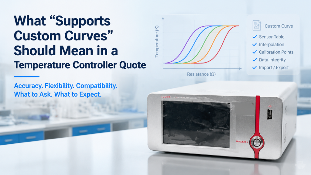
A cryogenic temperature controller quotation may contain a short sentence such as:
“Supports custom sensor curves.”
At first glance, this sounds clear.
But it can mean very different things:
- The controller contains several built-in standard curves.
- The user can select a sensor category but cannot upload individual calibration data.
- The supplier can load one custom curve at the factory.
- The buyer can upload curves independently.
- The controller accepts lookup tables but not polynomial coefficients.
- The controller stores a curve but uses it only for display.
- The curve can be used for temperature control, alarms, ramps, and data logging.
- The controller accepts only a limited number of points.
- The controller supports the curve mathematically but not the sensor’s electrical input.
These are not equivalent capabilities.
For Cernox-type resistance sensors, silicon diodes, Pt100 sensors, calibrated RTDs, and other cryogenic thermometers, a usable custom-curve function must cover more than file uploading.
The controller must be able to excite the sensor correctly, measure its electrical response, convert that response into temperature, assign the correct curve to the correct channel, preserve the curve after power loss, and apply the converted temperature to control and safety functions.
This article explains what temperature controller custom curves should mean in a serious quotation—and what buyers should verify before placing an order.
1. Why Temperature Sensors Need Response Curves
Most electronic temperature sensors do not directly produce a reading in kelvins.
They produce an electrical response related to temperature, such as:
- Resistance
- voltage
- thermoelectric voltage
- current
- another calibrated electrical quantity
The temperature controller measures that electrical response and converts it into temperature using a defined relationship.
Examples include:
- Resistance versus temperature
- voltage versus temperature
- temperature versus resistance
- temperature versus voltage
- polynomial coefficients
- interpolation tables
The conversion relationship is commonly referred to as a sensor curve, calibration curve, response curve, or temperature-response table.
2. Standard Curve vs. Custom Curve
A controller may contain two broad curve types.
Standard Curve
A standard curve represents the typical response of a sensor family.
Examples may include generic curves for:
- Silicon diode sensors
- platinum RTDs
- selected NTC resistance sensors
- thermocouples
A standard curve can be useful when interchangeability accuracy is acceptable.
Custom Curve
A custom curve represents:
- One individually calibrated sensor
- a user-developed sensor
- a sensor batch
- a nonstandard device
- a corrected standard sensor
- a specific calibration certificate
- a laboratory-defined response function
One commercial temperature-controller example includes built-in curves for silicon diodes, platinum RTDs, ruthenium oxide RTDs, and thermocouples, while also providing non-volatile storage for multiple 200-point calibrated or user-defined curves.
The quotation should state clearly whether “custom curve” means an individual sensor calibration or only selection from built-in standard curves.
3. A Custom Curve Does Not Create Sensor Compatibility
This is the most important purchasing distinction.
A controller may be able to store a resistance-versus-temperature table but still be unsuitable for the sensor.
Electrical compatibility must come first.
The controller must support the sensor’s:
- Electrical response type
- resistance or voltage range
- excitation method
- excitation current or voltage
- input resolution
- measurement accuracy
- lead configuration
- polarity requirements
- expected sensitivity
- self-heating limits
A file format cannot correct incompatible input hardware.
4. Sensor Curve Support Has Three Separate Layers
A serious quotation should address three layers.
Layer 1: Electrical Compatibility
Can the controller correctly measure the sensor?
Layer 2: Mathematical Compatibility
Can it convert the measured sensor value into temperature using the required curve?
Layer 3: Operational Compatibility
Can that converted temperature be used for:
- Closed-loop PID control
- setpoint ramps
- alarms
- output limits
- temperature zones
- data logging
- remote commands
- safety shutdown
A statement such as “supports custom curves” is incomplete unless all three layers are addressed.
5. Cernox-Type Sensor Support
Cernox-type sensors are cryogenic resistance thermometers.
For practical compatibility, the controller may need to support:
- The sensor’s full resistance range
- suitable resistance excitation
- four-wire measurement
- appropriate autoranging
- low measurement power
- individual calibration data
- the required temperature range
- stable readings in the intended magnetic environment
The custom curve must convert the measured resistance into temperature over the calibrated range.
But curve storage alone does not prove that the controller’s resistance-measurement hardware is suitable.
6. Silicon Diode Sensor Support
A silicon diode thermometer generally requires controlled current excitation and voltage measurement.
A controller intended for diode sensors should define:
- Excitation current
- voltage measurement range
- input resolution
- supported diode polarity
- built-in standard curves
- individual calibrated curve support
- valid temperature range
- overrange and underrange behavior
A resistance-input channel cannot necessarily measure a diode sensor correctly merely because the controller can store a voltage-temperature table.
7. Pt100 Sensor Support
A Pt100 is a platinum resistance thermometer with a nominal resistance of 100 Ω at 0°C.
A controller may support it through:
- A built-in standard platinum response curve
- a standard RTD equation
- an individually calibrated custom curve
- polynomial coefficients
- a lookup table
The buyer should confirm:
- Two-, three-, or four-wire support
- measurement-current level
- resistance range
- lead-resistance compensation
- temperature range
- standard curve used
- individual calibration support
- whether cryogenic use is genuinely supported
A controller that reads a Pt100 near room temperature may not automatically provide the required accuracy over an extended low-temperature range.
8. Built-In Curves Are Not Individual Calibrations
A standard sensor curve represents expected family behavior.
An individually calibrated sensor may be supplied with values specific to its serial number.
The individual curve may improve accuracy by accounting for sensor-to-sensor variation.
The buyer should therefore ask:
- Is the quoted sensor calibrated individually?
- Is a standard family curve being used?
- Is a custom curve file included?
- Who loads the curve?
- Does the controller retain the sensor serial number?
- Is the curve linked to a calibration certificate?
- What accuracy applies with each option?
A standard curve and an individual calibration curve should not be described as the same deliverable.
9. “Calibrated Sensor” and “Custom Curve” Are Different Deliverables
A calibrated sensor may be supplied with:
- Calibration points
- fitted coefficients
- interpolation equations
- uncertainty information
- calibration range
- sensor serial number
- calibration date
- traceability information
A custom curve is the digital representation loaded into the controller.
The curve may be derived from the calibration, but it is not automatically the complete calibration record.
The buyer should receive both when individual calibration is included:
- The calibration documentation
- The controller-compatible curve file
10. Curve Storage Capacity Must Be Stated
The quotation should state how many user curves the controller can store.
Useful questions include:
- How many built-in curves are available?
- How many custom curves can be stored?
- Are custom and standard curves stored separately?
- Does one curve occupy one sensor channel permanently?
- Can one curve be assigned to several channels?
- Can curves be deleted and replaced?
- Is storage retained after power loss?
- Are any slots reserved by the manufacturer?
One commercial controller example stores up to 39 individual 200-point calibrated or user curves in non-volatile memory. That is a product-specific capability, not a universal industry rule.
11. Curve Point Capacity Matters
A controller may limit each custom curve to:
- 20 points
- 50 points
- 100 points
- 200 points
- another fixed number
- a memory-based total
The point limit affects how accurately a nonlinear sensor response can be represented.
A sparse table may be adequate where:
- The response is smooth.
- temperature accuracy requirements are moderate.
- calibration points are placed intelligently.
- interpolation errors remain acceptable.
A denser table may be useful where:
- Sensor sensitivity changes rapidly.
- the temperature range is wide.
- high accuracy is required.
- the sensor response is strongly nonlinear.
The quotation should state the maximum number of points per curve.
12. More Points Do Not Automatically Mean More Accuracy
A 200-point curve is not automatically more accurate than a 50-point curve.
Accuracy also depends on:
- Quality of the original calibration
- calibration uncertainty
- distribution of points
- interpolation method
- numeric precision
- sensor stability
- excitation accuracy
- measurement noise
- self-heating
- thermal installation
Hundreds of poor-quality data points do not create a high-quality thermometer.
Curve capacity and calibration quality should be evaluated separately.
13. Curve Direction Must Be Defined
A sensor table may be written as:
- Temperature versus resistance
- resistance versus temperature
- temperature versus voltage
- voltage versus temperature
The controller may require one particular direction.
For example:
| Sensor Units | Temperature |
|---|---|
| Resistance | Kelvin |
or:
| Temperature | Sensor Units |
|---|---|
| Kelvin | Resistance |
The quotation should identify the accepted structure.
Otherwise, the buyer may receive calibration data that requires conversion before it can be loaded.
14. Accepted Units Must Be Defined
A controller may expect:
Temperature Units
- Kelvin
- degrees Celsius
- another defined scale
Sensor Units
- Ohms
- kilohms
- volts
- millivolts
- logarithmic resistance
- thermocouple voltage
Unit confusion can create severe errors.
For example:
- 1.2 kΩ entered as 1.2 Ω
- millivolts entered as volts
- Celsius values entered as kelvins
- log resistance entered as linear resistance
The curve file and controller interface should identify units explicitly.
15. Numeric Precision Should Be Specified
The controller should retain enough numeric precision for:
- Sensor units
- temperature values
- fitted coefficients
- interpolation
- remote readback
Questions include:
- How many significant digits can be stored?
- Is scientific notation accepted?
- Are very high resistances supported?
- Are sub-kelvin temperature values stored with sufficient resolution?
- Does file import round the data?
- Does displayed resolution differ from internal resolution?
A calibration file may contain high-resolution values that are degraded when imported into a controller with limited numeric storage.
16. Interpolation Method Matters
The controller must estimate temperatures between calibration points.
Possible methods include:
- Linear interpolation
- logarithmic interpolation
- polynomial fitting
- spline interpolation
- Chebyshev functions
- segmented equations
- manufacturer-specific algorithms
The quotation should state or document the interpolation method.
This matters because cryogenic sensor responses can be highly nonlinear.
The same calibration points can produce slightly different temperatures when different interpolation methods are used.
17. Calibration Points Should Cover the Real Operating Range
Suppose a sensor is calibrated from 1.4 K to 325 K.
The loaded curve should cover the temperatures the system will actually use.
Buyers should check:
- Lowest calibrated temperature
- highest calibrated temperature
- point density near critical regions
- sensor sensitivity across the range
- overlap between fitted sections
- behavior near curve endpoints
NIST’s cryogenic resistance-thermometer work describes comparison calibrations tied to ITS-90 over defined temperature ranges and emphasizes the use of calibrated thermometers, interpolation methods, and associated uncertainties.
A curve should not be assumed valid outside its documented calibration range.
18. Extrapolation Behavior Must Be Defined
What happens when the sensor reading falls outside the loaded curve?
Possible controller behavior includes:
- Display an overrange condition
- display an underrange condition
- return an invalid reading
- hold the nearest endpoint temperature
- extrapolate mathematically
- disable heater output
- activate an alarm
- continue operating with a warning
For temperature control, uncontrolled extrapolation can be risky.
The quotation should state:
- Whether extrapolation is allowed
- how far it is allowed
- how invalid readings are indicated
- what the heater output does
- whether alarms can be activated
19. The Curve Must Be Monotonic Where Required
Many temperature sensors have a response that consistently increases or decreases with temperature over a defined range.
A curve file containing:
- Reversed points
- duplicate sensor values
- out-of-order data
- local non-monotonic sections
- incorrect units
may fail to import or produce ambiguous conversions.
The controller or curve software should validate the curve before activation.
The buyer should ask whether the system checks:
- Point order
- duplicate points
- monotonicity
- valid units
- allowed range
- maximum point count
- missing data
20. File Format Must Be Disclosed
“Uploadable” is not useful unless the file format is known.
Possible formats include:
- CSV
- TXT
- XML
- JSON
- proprietary curve file
- polynomial coefficient file
- manually entered table
Ask:
- Is a file template provided?
- Are column headers required?
- What delimiter is used?
- Is a decimal point required?
- Are comments allowed?
- Is scientific notation accepted?
- What encoding is supported?
- Can spreadsheet data be converted easily?
- Is proprietary software required?
The buyer should receive a sample curve file before ordering when custom sensors are important.
21. Upload Method Must Be Defined
A controller may support curve loading through:
- Front panel
- USB
- Ethernet
- RS-232
- GPIB
- SD card
- vendor software
- SCPI commands
- Python driver
- factory service only
These options provide different levels of independence.
A buyer who regularly replaces calibrated sensors may need user-managed uploading.
A laboratory using one permanent sensor may be satisfied with factory loading.
The quotation should say exactly who can load, edit, export, and replace curves.
22. “Factory Loadable” Is Not the Same as “User Uploadable”
A supplier may say that custom curves are supported but require the buyer to send the calibration file back to the factory.
That may be acceptable for some projects.
But it creates:
- Longer replacement time
- dependence on the vendor
- possible service charges
- international support delays
- risk if the original curve is lost
The quotation should distinguish among:
- Factory-loaded only
- distributor-loaded
- user-uploadable
- remotely uploadable
- front-panel editable
- command-interface programmable
23. Curve Editing Should Be Controlled
Users may need to:
- Add a point
- correct a file
- change metadata
- replace a sensor
- extend a calibration range
- delete an old curve
But uncontrolled editing creates risk.
A useful controller or curve-management tool should support:
- Backup before modification
- clear curve identification
- change date
- version number
- import validation
- export
- deletion protection
- audit trail, where required
An accidental curve edit can change every temperature result produced by that channel.
24. Curves Should Be Exportable
A buyer should be able to back up custom curves.
Ask whether curves can be:
- Read from the controller
- exported to a file
- copied to another controller
- archived with project data
- compared with the original file
- restored after service
- transferred during controller replacement
Curve storage without export capability creates a single point of failure.
25. Curve Metadata Should Be Preserved
Useful metadata includes:
- Curve name
- sensor manufacturer
- sensor model
- sensor serial number
- calibration date
- calibration range
- sensor-unit type
- temperature coefficient
- curve version
- source file name
- responsible laboratory
- notes
The controller may not store every metadata field internally.
If not, the external curve register should preserve them.
A file called Curve_01.txt is not sufficient for long-term traceability.
26. Curve Assignment Must Be Channel-Specific
A multi-input controller should allow the correct curve to be assigned to each sensor channel.
Example:
- Input A: calibrated Cernox-type sensor
- Input B: silicon diode sensor
- Input C: Pt100
- Input D: another calibrated RTD
The system should prevent accidental use of:
- The Cernox curve on the diode channel
- the Pt100 curve on the sample sensor
- a previous sensor’s curve after replacement
Ask whether the channel display shows:
- Active curve number
- curve name
- sensor type
- sensor units
- input range
27. The Curve Should Affect More Than the Display
A weak implementation may use a curve only to show temperature on the front panel.
A complete implementation should allow the converted temperature to support:
- PID control
- setpoint comparison
- temperature ramps
- temperature zones
- alarm thresholds
- heater-output limits
- analog outputs
- remote readback
- logging
- safety logic
The quotation should confirm whether custom-curve temperatures are fully usable by all relevant controller functions.
28. PID Control Must Use the Correct Curve
A PID loop reacts to the difference between measured temperature and setpoint.
If the active curve is wrong:
- The displayed temperature is wrong.
- the control error is wrong.
- the heater output is wrong.
- temperature-zone transitions may occur at the wrong time.
- alarm limits may be ineffective.
- the stage may overshoot.
The custom curve is therefore part of the control system—not only part of the display configuration.
29. Temperature Zones Must Remain Compatible
Some controllers use temperature zones to change:
- PID values
- heater range
- ramp rate
- control input
- output limit
If a custom curve replaces an existing sensor curve, confirm that:
- Zone boundaries remain within the curve range.
- the intended sensor is selected in each zone.
- sensor switching is valid.
- the heater does not operate outside the sensor’s calibrated range.
- zone transitions are tested.
Loading a curve without reviewing the associated control configuration can create unexpected behavior.
30. Alarm Logic Must Use Valid Temperature Data
A temperature alarm may trigger:
- Heater shutdown
- magnet shutdown
- optical-source shutdown
- cryocooler protection
- warning relay
- software notification
The buyer should ask what happens when:
- The curve is missing.
- the sensor reading is outside the curve.
- the sensor is disconnected.
- the active curve does not match the input type.
- imported data is invalid.
- the sensor value is overrange.
A safe controller should not continue normal heater operation using an invalid temperature conversion.
31. Sensor Excitation Must Match the Calibration Condition
Calibration data may be generated using a defined electrical excitation.
Changing excitation can affect the measured sensor response through:
- Self-heating
- voltage drop
- current dependence
- measurement noise
The controller should provide appropriate excitation for the sensor and application.
The buyer should compare:
- Calibration excitation
- controller excitation
- sensor power dissipation
- installation thermal resistance
- required accuracy
A perfect curve cannot correct a sensor that is heated significantly by the measurement current.
32. Four-Wire Compatibility Should Be Confirmed
For resistance sensors, four-wire measurement helps reduce errors from lead resistance.
The buyer should ask:
- Does every required input support four-wire measurement?
- Are current and voltage leads separated to the sensor?
- Does the cryostat include enough wiring?
- Is compensation performed in hardware or software?
- Can the controller switch between two- and four-wire modes?
- Does the custom curve assume a particular wiring method?
Custom-curve support does not solve inadequate sensor wiring.
33. Input Autoranging Should Be Reviewed
A resistance sensor may change by orders of magnitude across the temperature range.
The controller may need to change:
- Resistance range
- excitation
- measurement gain
- filtering
Ask:
- Is autoranging supported?
- Does autoranging interrupt control?
- Is there a dead zone during range changes?
- Can ranges be fixed manually?
- Does the curve remain valid across all ranges?
- Are range transitions visible in raw data?
- Can autoranging create control instability?
The electrical measurement chain must support the full curve, not only one portion.
34. Magnetic-Field Use Should Be Declared
Cryogenic sensors may be used inside:
- Electromagnets
- Helmholtz coils
- superconducting magnets
- Hall systems
- VSM platforms
- cryogenic transport systems
The buyer should state:
- Maximum magnetic field
- field direction
- sensor orientation
- temperature range
- required accuracy in field
- whether field-dependent correction data is available
A zero-field calibration curve does not automatically account for every magnetic-field-related effect.
If field correction is required, ask whether the controller can store or apply it, or whether correction must be performed externally.
35. One-Dimensional Curves Have Limits
A normal sensor curve converts one measured electrical value into temperature.
It does not automatically account for additional variables such as:
- Magnetic field
- pressure
- sensor orientation
- measurement current
- thermal history
- radiation
- mechanical strain
If temperature depends on both sensor reading and magnetic field, the system may need:
- Separate correction tables
- external software correction
- several field-specific curves
- a multidimensional model
- post-processing
The quotation should not call a basic one-dimensional curve function a complete magnetic-field correction system.
36. Custom Curve Support Does Not Guarantee Traceability
A controller can store a curve created from:
- A traceably calibrated sensor
- an internal laboratory comparison
- an unverified dataset
- a theoretical equation
- copied catalogue data
The controller cannot determine the metrological quality of the source data.
NIST defines metrological traceability through a documented unbroken chain of calibrations, with each calibration contributing to measurement uncertainty. NIST also notes that traceability alone does not guarantee fitness for purpose; the resulting uncertainty must suit the measurement need.
Therefore:
A custom curve is a conversion tool. It is not automatically proof of traceable calibration or suitable uncertainty.
37. The Calibration Certificate Should Match the Loaded Curve
Before acceptance, compare:
- Sensor serial number
- calibration range
- calibration points
- curve file
- temperature units
- sensor units
- calibration date
- excitation condition
- version number
The buyer should be able to connect:
- Physical sensor
- Calibration certificate
- Curve file
- Controller curve slot
- Assigned input channel
A broken link in this chain creates avoidable uncertainty.
38. Sensor Replacement Workflow
Sensors can be damaged or replaced.
The quotation should explain the replacement process.
Ask:
- Can the user install another sensor of the same type?
- Can a standard curve be selected immediately?
- Can a new individual curve be uploaded?
- Is factory support required?
- How is the old curve archived?
- Can the new sensor serial number be recorded?
- Must PID settings be reviewed?
- Must FAT or SAT checks be repeated?
A controller may support custom curves technically but still have an inconvenient replacement workflow.
39. Controller Replacement Workflow
If the controller fails and is replaced, the laboratory should be able to restore:
- Custom curves
- channel assignments
- PID settings
- temperature zones
- alarms
- heater limits
- communication settings
- sensor metadata
Ask whether the supplier provides:
- Full configuration backup
- curve export
- restoration software
- configuration report
- spare-controller transfer procedure
Curve portability can be important for long-term system maintenance.
40. Software and Remote Interface Requirements
For automated laboratories, custom curves may need to be managed through:
- SCPI
- Python
- LabVIEW
- Ethernet
- USB
- serial interface
- vendor curve software
The buyer should confirm whether the remote interface can:
- List curves
- read curve metadata
- upload points
- export points
- assign curves to channels
- delete user curves
- detect invalid imports
- verify active curves
- back up the configuration
One commercial manufacturer provides curve-management software and programming interfaces for uploading and manipulating calibrated or user-defined sensor curves.
41. Cybersecurity and IT Restrictions
Some university and corporate networks restrict:
- Installing vendor software
- connecting USB devices
- using administrator privileges
- connecting instruments to Ethernet
- running unsigned drivers
- using cloud services
Before purchase, ask:
- Is curve loading possible without internet access?
- Can files be transferred using a standard method?
- Is administrator access required?
- Is the software compatible with the laboratory’s operating system?
- Can curves be loaded through documented commands?
- Is offline installation supported?
A curve feature is less useful if the buyer’s IT environment prevents access to it.
42. Factory-Loaded Curves
Factory loading can be valuable when:
- The sensor is supplied with the controller.
- the sensor has an individual calibration.
- the buyer wants a ready-to-use package.
- input configuration is complex.
- the system will be tested before shipment.
The supplier should document:
- Curve slot
- curve name
- sensor serial number
- assigned input
- valid range
- source file
- import date
- verification result
Factory loading should be part of FAT, not merely an undocumented setup step.
43. User-Defined Curves
User-defined curves are useful when the laboratory:
- Calibrates its own sensors
- uses third-party sensors
- develops custom thermometers
- replaces sensors regularly
- needs correction curves
- operates several cryostats
- shares one controller between experiments
The quotation should clarify whether using third-party curves affects:
- Warranty
- measurement specifications
- technical support
- curve validation
- controller safety
- system acceptance
A supplier may support user curves without accepting responsibility for the accuracy of user-provided calibration data.
44. What Should Be Included in FAT?
Factory Acceptance Testing for custom curves may include:
Curve Import
- Load the supplied file.
- verify accepted point count.
- confirm units.
- confirm metadata.
- check import warnings.
Input Assignment
- Assign curve to the correct channel.
- confirm sensor type.
- confirm electrical input range.
- confirm excitation.
Conversion Verification
- Apply known simulated sensor values.
- compare displayed temperature with the curve.
- test several points across the range.
- check interpolation between points.
Control Verification
- Use the custom curve as the PID input.
- change setpoint.
- test ramps and zones.
- verify heater output.
- test alarms.
Fault Verification
- Simulate overrange.
- simulate underrange.
- disconnect sensor.
- load an invalid curve.
- confirm safe response.
Backup Verification
- Export the curve.
- back up the controller configuration.
- confirm restoration method.
45. Simulated Sensor Testing
A resistance box, voltage source, sensor simulator, or calibrated electrical source can help test curve conversion without cooling the complete system.
At selected calibration points, the FAT can compare:
- Applied sensor value
- expected temperature
- displayed temperature
- remote temperature readback
- alarm condition
- control response
This helps separate:
- Controller conversion performance
- sensor performance
- cryostat installation
- thermal-equilibrium effects
A complete cryogenic test may still be required, but electrical simulation provides a useful first verification.
46. Cryogenic Verification Still Matters
Room-temperature simulation cannot verify:
- Sensor self-heating at low temperature
- thermal anchoring
- wiring heat leak
- sample-stage gradients
- sensor mounting
- magnetic-field influence
- cryostat control stability
Where cryogenic performance is part of the purchase, acceptance should include selected real-temperature points.
NIST’s low-temperature calibration work demonstrates that cryogenic resistance-thermometer calibration is performed over defined ranges using reference thermometers, controlled comparison methods, interpolation, and documented uncertainties—not only room-temperature electrical checks.
47. Data Package Buyers Should Request
The final delivery package may include:
- Sensor calibration certificate
- original calibration data
- controller-compatible curve file
- curve-file template
- curve slot number
- active channel assignment
- sensor serial number
- sensor type
- valid temperature range
- excitation setting
- wiring method
- PID settings
- zone settings
- alarm limits
- FAT conversion results
- controller configuration backup
- curve upload instructions
- curve export instructions
This package makes future support much easier.
48. Better RFQ Language
Weak RFQ
“The controller should support custom curves.”
Better RFQ
“The cryogenic temperature controller shall support user-uploadable custom sensor calibration curves for individually calibrated resistance and diode thermometers. Please state the supported sensor input types, resistance and voltage ranges, excitation options, two- or four-wire capability, number of user-curve slots, maximum points per curve, interpolation method, accepted file format, units, upload and export methods, non-volatile storage, channel assignment, metadata capability, and behavior outside the valid curve range.
Custom-curve temperatures must be available for display, remote readback, PID control, setpoint ramps, temperature zones, alarms, logging, and heater-safety functions. Please also include the FAT procedure for curve import, sensor simulation, interpolation checks, fault handling, configuration backup, and restoration.”
49. Better RFQ for Cernox, Diode, and Pt100 Sensors
“We require a cryogenic temperature controller that can support the following sensors:
- One individually calibrated Cernox-type resistance thermometer
- one calibrated silicon diode sensor
- one Pt100 sensor
- one spare sensor input
Please confirm the electrical measurement method for each sensor, excitation, resistance or voltage range, four-wire support, input accuracy, compatible temperature range, standard curves, individually calibrated user curves, curve storage, channel assignment, sensor serial-number records, and independent curve upload.
The quotation shall distinguish between standard sensor curves, individually calibrated curves, and user-generated curves. Calibration certificates and controller-compatible files shall be supplied for all individually calibrated sensors.”
50. Common Buyer Mistakes
Mistake 1: Assuming Curve Support Means Sensor Support
The controller’s electrical input must match the sensor.
Mistake 2: Confusing Built-In Curves with Individual Calibration
A standard family curve is not the same as a serial-number-specific calibration.
Mistake 3: Not Asking About Point Capacity
A custom curve may be limited to a small number of data points.
Mistake 4: Ignoring File Format
The calibration laboratory’s file may not be directly importable.
Mistake 5: Ignoring Interpolation
Temperatures between calibration points depend on the controller’s interpolation method.
Mistake 6: Assuming Extrapolation Is Safe
Operation outside the calibrated range should have defined behavior.
Mistake 7: Forgetting Curve Backup
A custom curve should be exportable and recoverable.
Mistake 8: Not Matching Sensor Serial Numbers
The curve must belong to the installed physical sensor.
Mistake 9: Checking Only the Display
The custom curve should also work with PID control, alarms, ramps, logging, and safety logic.
Mistake 10: Treating a Curve as Proof of Traceability
Traceability depends on the calibration chain, documentation, and uncertainty—not merely a file stored in the controller.
51. How Cryomagtech Supports Custom Sensor Curves
Cryomagtech supplies cryogenic temperature controllers, temperature monitors, Cernox-type sensors, silicon diode sensors, Pt100 sensors, heaters, cryogenic wiring, Hall measurement systems, cryostat-integrated magnetic platforms, and custom Magnet & Field Systems.
For custom-curve temperature measurement projects, we help evaluate:
- Sensor electrical compatibility
- standard vs. individually calibrated curves
- resistance and diode inputs
- excitation and self-heating
- two- and four-wire measurement
- temperature range
- custom curve capacity
- point limits
- accepted formats
- curve upload and export
- channel assignment
- curve metadata
- sensor serial-number tracking
- PID and alarm integration
- cryogenic wiring
- magnetic-field application
- calibration documentation
- FAT and SAT verification
- configuration backup
- future sensor replacement
“Supports custom curves” should not be accepted as a complete specification.
A useful quotation should explain exactly which sensors can be measured, which curve formats can be loaded, how those curves are managed, and whether the converted temperature can safely control the real cryogenic system.
References
- Lake Shore Cryotronics – Model 336 Cryogenic Temperature Controller
https://www.lakeshore.com/products/product-detail/model-336/more - NIST – Calibration of Cryogenic Resistance Thermometers Between 0.65 K and 165 K on ITS-90
https://www.nist.gov/publications/calibration-cryogenic-resistance-thermometers-between-065-k-and-165-k-international - NIST – Policy on Metrological Traceability
https://www.nist.gov/calibrations/traceability
Key Takeaways
- Temperature controller custom curves must be evaluated at the electrical, mathematical, and operational levels.
- A controller may store a curve while still being electrically incompatible with the sensor.
- Standard sensor curves and individually calibrated curves are different deliverables.
- Cernox-type resistance sensors, silicon diodes, and Pt100 sensors require different measurement and excitation methods.
- Buyers should define curve slots, point capacity, units, numeric precision, interpolation, file format, upload method, and export capability.
- The custom curve should be usable for PID control, alarms, ramps, zones, logging, remote readback, and safety functions—not only display.
- Curve behavior outside the calibrated range must be defined.
- Sensor serial number, calibration certificate, curve file, controller slot, and input channel should remain linked.
- A custom curve does not automatically establish metrological traceability or measurement uncertainty.
- FAT should test curve import, interpolation, sensor simulation, PID use, fault handling, backup, and restoration.
For cryogenic temperature controller procurement, the key question is not only:
“Does the controller support custom curves?”
The better question is:
“Can it correctly measure our specific sensor, load and preserve its calibration data, and use that converted temperature reliably for control, safety, logging, and future maintenance?”