
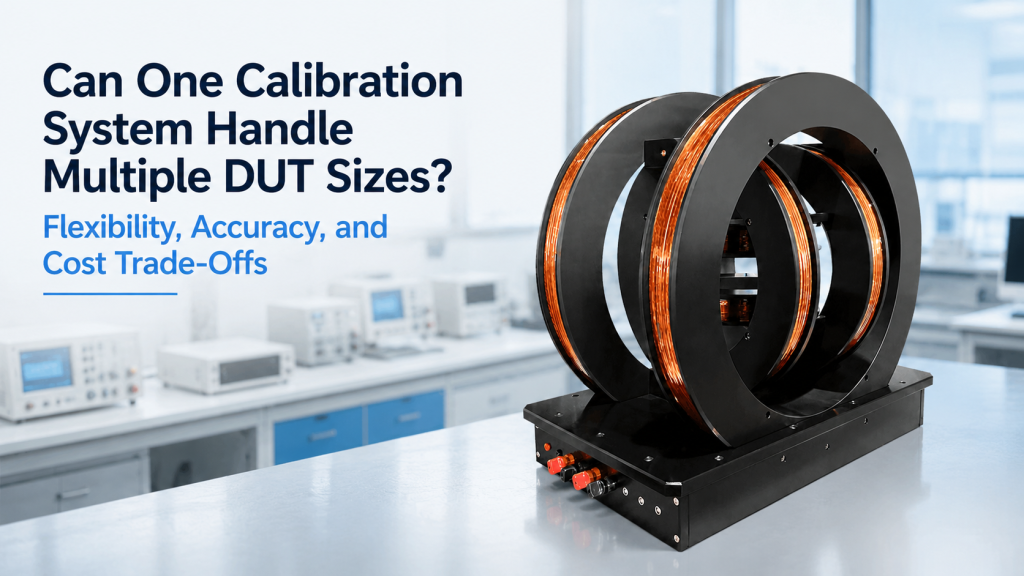
Many calibration laboratories want one platform that can test everything.
A buyer may ask:
“Can the same three-axis Helmholtz coil calibrate a small magnetometer chip, an IMU module, an electronic compass board, and a complete device?”
The answer is often yes—but only within defined limits.
A well-designed calibration system for multiple DUT sizes can reduce equipment investment, save laboratory space, simplify training, and support future products. However, greater flexibility can also increase coil size, power requirements, fixture complexity, positioning uncertainty, calibration workload, and total project cost.
The real challenge is not simply making the largest DUT fit inside the coils.
The system must also keep each device under test, or DUT, inside the qualified uniform-field volume with controlled position, orientation, wiring, magnetic cleanliness, and repeatable mounting.
This article explains how buyers should evaluate flexibility, accuracy, and cost when selecting a three-axis Helmholtz coil and calibration platform for multiple DUT sizes.
1. What “Multiple DUT Sizes” Really Means
Multiple DUT sizes may refer to very different situations.
A laboratory might need to calibrate:
- Individual magnetometer sensors
- small printed circuit boards
- IMU modules
- electronic compass modules
- automotive sensor assemblies
- handheld electronic devices
- drone navigation units
- satellite attitude-control hardware
- several sensors mounted in one fixture
- future products that do not yet have final dimensions
The important specification is not only the physical size of each DUT.
The buyer should also define:
- Sensor location inside the enclosure
- cable and connector position
- mounting fixture
- required orientation
- rotation envelope
- number of devices tested together
- uniformity requirement
- field range
- acceptable positioning uncertainty
A device may fit physically inside the coil while its sensing element sits outside the qualified calibration volume.
2. The Uniform-Field Volume Is the Real Size Limit
A three-axis Helmholtz coil is designed to produce a nearly uniform magnetic field near its center.
The University of Surrey describes a facility using three orthogonal coil pairs to create a nearly uniform magnetic field within an experimental control volume. Its control volume is large enough to accommodate a 27U CubeSat, illustrating how coil dimensions can be selected around the test item rather than only around an individual sensor.
But the full open space inside a coil system is not necessarily the uniform-field volume.
Buyers should distinguish between:
- Physical opening: The space through which a DUT can be inserted
- mechanical test volume: The space available after fixtures and cables are installed
- qualified uniform-field volume: The region where field uniformity meets the specified tolerance
- usable calibration volume: The region where the DUT’s sensing elements can be positioned repeatably
The smallest of these determines what can actually be calibrated.
3. A DUT’s Outer Dimensions May Be Misleading
Suppose a device enclosure measures 200 mm × 100 mm × 50 mm.
That does not automatically mean the calibration system needs a 200 mm uniform-field region.
The critical information is where the magnetic sensors are located.
Case A: Sensor Near the Center
If the magnetometer is near the geometric center, a smaller uniform-field volume may be sufficient even though the enclosure is large.
Case B: Sensor Near One Edge
If the sensor is 30 mm from one end, the fixture must place that location—not the enclosure center—at the magnetic center.
Case C: Multiple Distributed Sensors
If several magnetometers are distributed across the device, the uniform-field region may need to cover all sensors simultaneously.
The RFQ should therefore include a drawing showing the sensing location inside each DUT.
4. Rotation Envelope Can Be Larger Than DUT Size
Magnetometer, IMU, and electronic compass calibration often requires the DUT to be tested in multiple orientations.
If the DUT rotates inside the coil system, its required clearance may be determined by its diagonal dimension rather than its width or height.
A rectangular DUT that fits when stationary may collide with:
- Coil frames
- adjacent axes
- support structures
- cables
- reference probes
- safety enclosures
during rotation.
Buyers Should Define
- Rotation around one, two, or three axes
- full 360° rotation or limited angular positions
- rotation center
- maximum diagonal envelope
- cable movement during rotation
- clearance from coil windings
- manual or motorized rotation
- required angular accuracy
The correct system size should be based on the complete swept volume.
5. Fixtures Consume Part of the Calibration Volume
The DUT is not installed by itself.
A practical setup may also include:
- Mounting plate
- rotation stage
- clamps
- adapter bracket
- connector support
- cable strain relief
- non-magnetic fasteners
- reference magnetometer
- optical alignment target
- temperature sensor
These components occupy space and may move the DUT away from the coil center.
A calibration system described as having a 300 mm opening may offer much less usable space after the fixture is installed.
The supplier should evaluate the complete fixture-and-DUT assembly.
6. Flexibility Is Not the Same as Accuracy
A platform may physically support many DUT sizes while producing inconsistent calibration results.
Accuracy depends on more than available space.
It may be affected by:
- Field uniformity
- field stability
- DUT positioning
- axis alignment
- fixture repeatability
- rotation accuracy
- background magnetic field
- reference probe location
- cable movement
- magnetic materials near the DUT
- calibration procedure
- measurement uncertainty
NIST notes that metrological traceability alone does not guarantee fitness for purpose; the associated measurement uncertainty must also be sufficiently small for the intended measurement need.
The practical lesson is clear:
A universal fixture is useful only if its added positioning and mounting uncertainty remains acceptable.
7. Larger Coils Offer More Flexibility—but at a Cost
Increasing coil size can create a larger working volume and make it easier to accommodate different DUTs.
But larger coils may require:
- More copper
- larger support frames
- higher current
- higher voltage
- more powerful drivers
- stronger cooling
- more installation space
- higher shipping cost
- more rigorous structural alignment
For a classical Helmholtz pair, the center field depends on coil radius, number of turns, and current. Increasing the coil radius while keeping the same number of turns and current reduces the center field, so a larger system may need more ampere-turns to achieve the same field.
A larger coil is therefore not a free increase in flexibility.
8. Larger Uniform Volume May Reduce Maximum Field or Raise Power
A buyer may request:
- Large DUT capacity
- strong magnetic field
- tight uniformity
- compact overall size
- low power consumption
- low cost
These goals can conflict.
A large uniform volume may require:
- Larger coil diameter
- optimized multi-coil geometry
- higher current
- more turns
- greater voltage headroom
- active cooling
- a larger mechanical frame
The supplier should state the trade-off among:
- Maximum field
- uniformity tolerance
- uniformity volume
- coil size
- driver power
- duty cycle
- cost
Buyers should avoid comparing systems only by maximum field or external dimensions.
9. Three-Axis Architecture Adds Mechanical Constraints
A three-axis Helmholtz coil uses orthogonal coil pairs to synthesize a magnetic field with the desired direction and magnitude. Such systems are used for applications including background-field cancellation and navigation magnetometer calibration.
However, nested X, Y, and Z coils create less open access than a single-axis pair.
The design must consider:
- Inner-axis opening
- outer-axis support structure
- fixture insertion direction
- rotation-stage access
- cable exit paths
- maintenance access
- axis alignment
- mechanical interference
The smallest inner axis often determines the practical DUT limit.
10. The Magnetic Center Must Be Defined
For a multi-size system, every fixture should place the relevant sensing point at the same defined magnetic center.
That center should be documented relative to:
- Coil frame references
- fixture mounting holes
- rotation-axis intersection
- DUT datum surfaces
- reference probe location
- coordinate system origin
Without a common mechanical datum, each new fixture may create a different sensor position.
The field may be stable, but the DUT may not be measuring the same field.
11. Positioning Error Becomes More Important for Large DUTs
A small sensor can often be positioned close to the field center.
A large device may extend toward the edge of the qualified volume, where field variation is greater.
This makes the calibration more sensitive to:
- Fixture placement
- sensor-location tolerance
- enclosure manufacturing tolerance
- rotation-axis offset
- cable force
- stage backlash
- operator technique
The larger the DUT relative to the uniform-field volume, the less margin remains for positioning error.
12. Small DUTs Have Their Own Challenges
Large devices create clearance problems.
Small devices create handling and positioning problems.
A very small sensor may need:
- Microscope-assisted alignment
- fine adjustment
- compact non-magnetic holder
- wire-bond or probe access
- strain relief
- controlled sensor-axis orientation
- repeatable PCB datum points
A fixture designed mainly for large enclosures may not position a tiny sensor accurately enough.
One calibration platform may therefore need dedicated inserts for different DUT classes.
13. The Fixture Should Reference the Sensor, Not Only the Enclosure
A universal clamp may hold many enclosure sizes.
But enclosure surfaces are not always reliable calibration references.
Possible problems include:
- Sensor is not centered inside enclosure.
- PCB moves inside housing.
- enclosure tolerances are large.
- connector position changes between revisions.
- product label does not show sensor orientation.
- different product variants use different internal layouts.
A better fixture references stable mechanical datums tied to the known sensor location.
The fixture drawing should identify:
- DUT origin
- sensor coordinates
- X/Y/Z sensing directions
- connector orientation
- mounting datum
- rotation center
14. Coordinate-System Definition Is Essential
Calibration errors can occur even when the magnetic field is correct.
The coil coordinate system and DUT coordinate system may use different conventions.
For example:
- Coil +X may point east.
- DUT +X may point toward the connector.
- software may use a right-handed coordinate system.
- product firmware may report another axis order.
- one fixture may install the DUT upside down.
A multi-DUT platform should define:
- Coil X/Y/Z axes
- DUT X/Y/Z axes
- positive field direction
- positive rotation direction
- fixture orientation
- software transformation
- reported output units
A fixture-specific coordinate map may be needed for each DUT model.
15. Reference Probe Placement Can Compete with DUT Space
A calibration system may use a reference magnetometer to verify or control the field.
The reference probe should ideally measure the same field experienced by the DUT.
But both cannot always occupy the exact same point.
An IEEE-published triaxial magnetometer calibration study notes that the relative placement of sensors can contribute to calibration uncertainty when both cannot be located at the most homogeneous central position.
For larger DUTs, buyers should clarify:
- Is the reference probe installed permanently?
- Is it removed before DUT testing?
- Is it beside or inside the DUT?
- Is the field measured before each test?
- Is a transfer calibration used?
- Does probe placement reduce usable volume?
Reference-probe strategy is part of the platform design.
16. One Large DUT or Several Small DUTs?
Some laboratories want to calibrate several devices simultaneously.
This can increase throughput, but it changes the uniformity requirement.
If four sensors are mounted across a fixture, the field must meet the required tolerance at all four sensing locations.
The system may need:
- Larger uniform-field volume
- tighter fixture tolerances
- channel synchronization
- multiple cable routes
- fixture-specific mapping
- identification of each DUT position
- correction factors for position differences
Testing several DUTs at once is not equivalent to calibrating one DUT four times at the center.
17. Magnetic Cleanliness of Fixtures Matters
Fixtures should avoid introducing unwanted magnetic fields.
Potentially problematic materials include:
- Carbon steel screws
- magnetic stainless steel
- permanent-magnet latches
- loudspeakers
- motors
- magnetized tools
- steel bearing components
- magnetic connector shells
- nickel-rich plated hardware
Suitable fixture materials may include carefully selected:
- Aluminum
- brass
- polymers
- fiberglass composites
- ceramics
- verified low-magnetic stainless components
Material names alone are not always enough.
Purchased hardware may need practical magnetic screening because composition and cold working can affect magnetic behavior.
18. Larger Fixtures Can Disturb the Field More
A small non-magnetic sensor holder may have negligible influence.
A large fixture may include enough conductive or weakly magnetic material to affect:
- Background field
- field distribution
- AC response
- eddy currents
- rotation torque
- measurement repeatability
For DC calibration, conductive materials may be manageable.
For time-varying field testing, large conductive structures can create additional effects.
The supplier should review fixture material, size, and frequency range together.
19. Cable Routing Must Work for Every DUT Size
Different DUTs may use different:
- Cable counts
- connector positions
- power requirements
- communication interfaces
- bending radii
- rotation paths
Poor cable routing can:
- Pull the DUT away from center
- change orientation
- limit rotation
- create loops
- add magnetic contamination
- introduce triboelectric or induced noise
- block insertion of larger devices
A flexible platform needs a defined cable-management strategy, not only an adjustable fixture.
20. Repeatable Remounting Is Part of Calibration Quality
A calibration result should not depend strongly on which operator mounted the DUT.
Repeatability can be improved through:
- Datum pins
- hard mechanical stops
- keyed orientation
- kinematic mounting
- indexed rotation
- torque-controlled fasteners
- dedicated inserts
- digital position readout
- fixture identification
- documented setup procedures
A universal fixture with many loosely adjustable clamps may be flexible but difficult to reproduce.
Dedicated adapters on a common base often provide a better balance.
21. Universal Base with Dedicated Inserts
One effective architecture is:
- One three-axis Helmholtz coil platform
- one central fixture interface
- several DUT-specific inserts or adapter plates
Advantages
- Common magnetic system
- consistent center reference
- lower cost than several complete platforms
- easier future expansion
- better repeatability than a fully universal clamp
- fixture-specific identification and calibration files
Limitations
- Each new DUT may need a new insert.
- fixture design still requires engineering.
- large changes in DUT envelope may exceed the original platform.
- each insert may require verification.
This architecture is often more realistic than one fixture that physically adjusts to everything.
22. Adjustable Rails and Sliding Platforms
An adjustable platform may use:
- Linear rails
- slotted plates
- threaded stages
- telescoping supports
- movable clamps
- height-adjustable columns
These help accommodate different dimensions.
But the buyer should ask:
- How is the final position measured?
- How is it locked?
- What is the positioning repeatability?
- Does movement preserve the sensor center?
- Are rails magnetically suitable?
- Can positions be recorded?
- Does the fixture sag under heavier DUTs?
Mechanical flexibility without position control can reduce calibration confidence.
23. Rotation Stage Selection
A rotation stage may be manual or motorized.
Manual Rotation
Useful when:
- Angular positions change infrequently.
- throughput is moderate.
- trained operators are available.
- budget is limited.
Motorized Rotation
Useful when:
- Many orientations are required.
- calibration sequences are automated.
- angular repeatability matters.
- remote operation is needed.
- data must be synchronized with orientation.
Motorized stages may introduce:
- Magnetic materials
- motors near the field volume
- cables
- electrical noise
- backlash
- additional software
The stage should be evaluated as part of the magnetic calibration system.
24. Whole-Device Rotation vs. Electronic Field Rotation
A three-axis coil can change the magnetic field vector electronically.
This may reduce the need to rotate the DUT mechanically.
The IEEE calibration study cited earlier used a triaxial coil method that did not require movement of the magnetometer during calibration.
Electronic vector rotation offers potential benefits:
- Fewer moving parts
- reduced cable motion
- faster automation
- lower collision risk
- easier testing of large DUTs
- repeatable field direction
But it does not solve every problem.
Mechanical rotation may still be required when testing:
- Orientation-dependent mounting errors
- gravity interaction in IMUs
- combined accelerometer and magnetometer behavior
- enclosure-induced effects
- full system-level navigation performance
The calibration method should determine whether a rotation stage is necessary.
25. IMU Calibration May Need More Than Magnetic Field
An IMU can include:
- Magnetometers
- accelerometers
- gyroscopes
- temperature sensors
- embedded algorithms
A Helmholtz coil directly controls the magnetic test environment.
It does not create controlled acceleration or angular velocity by itself.
A combined IMU calibration platform may therefore require:
- Precision rotation stage
- tilt table
- temperature chamber
- synchronization
- data acquisition
- magnetic field generation
- mechanical coordinate alignment
The buyer should distinguish between:
- Magnetometer calibration
- electronic compass calibration
- magnetic-heading validation
- full IMU calibration
These are not identical scopes.
26. Electronic Compass Testing May Need Device-Level Evaluation
An electronic compass may be affected by magnetic components inside the final product.
Testing only the bare sensor may not reveal:
- PCB current effects
- speaker magnets
- battery-related fields
- steel screws
- enclosure hardware
- motor interference
- cable-current effects
- magnetic offsets after assembly
A platform that supports both bare sensor modules and assembled devices can be valuable.
However, the full device may need a much larger uniform volume and a different fixture.
27. Magnetometer Calibration Accuracy Depends on the Full Setup
A high-quality coil alone does not guarantee a high-quality calibration.
The complete uncertainty budget may include:
- Reference field uncertainty
- current measurement
- field stability
- background field
- coil orthogonality
- field uniformity
- DUT positioning
- angular alignment
- reference probe positioning
- temperature
- data processing
- repeatability
The IEEE calibration study achieved precise sensitivity and orthogonality results using calibrated triaxial coils, a scalar reference magnetometer, and a defined calibration procedure—not coil hardware alone.
Buyers should ask what performance is guaranteed at system level.
28. One Calibration File May Not Fit Every Fixture
Different DUT fixtures may change:
- Sensor position
- angular orientation
- reference-probe relationship
- cable configuration
- magnetic background
- usable field range
The system may therefore need:
- Fixture identification
- DUT-specific coordinate transformation
- position-specific correction
- calibration date
- allowed field range
- temperature condition
- software recipe
- uncertainty statement
A flexible platform should manage configurations rather than relying on operator memory.
29. Automatic Fixture Recognition
For high-throughput systems, the platform may identify the installed fixture through:
- Barcode
- QR code
- RFID
- electrical ID
- software selection
- mechanical coding
The control software can then load:
- DUT dimensions
- field limits
- calibration table
- rotation sequence
- cable configuration
- coordinate transformation
- safety limits
- report template
This reduces the risk of applying the wrong calibration method to a different DUT.
30. Field Mapping Should Cover the Real DUT Positions
Field mapping is often performed at the coil center.
For a multi-size platform, it may be more useful to map:
- The full qualified volume
- common sensor positions
- rotation path
- multi-DUT fixture locations
- reference-probe position
- maximum fixture envelope
The mapping report should state:
- Coordinate system
- grid spacing
- field level
- background-field treatment
- probe used
- uncertainty
- fixture condition
- pass/fail calculation
A center-point measurement cannot verify a large multi-DUT working volume.
31. Acceptance Should Include More Than an Empty Coil Test
The empty coil performance is important.
But a multi-size calibration platform should also be checked with representative fixtures.
Possible FAT items include:
- Uniformity mapping
- X/Y/Z field verification
- axis orthogonality
- field stability
- fixture installation
- sensor-center positioning
- repeated mounting
- rotation clearance
- cable routing
- software recipe selection
- DUT-specific report output
- safety limits
- largest representative DUT
- smallest representative DUT
This confirms that the delivered platform works as an integrated system.
32. Define a Qualified DUT Envelope
Instead of saying:
“The system supports different DUT sizes,”
define a qualified envelope.
Example
“The platform shall support DUTs from 30 mm × 30 mm × 10 mm to 250 mm × 180 mm × 100 mm, with a maximum mass of 5 kg. The magnetic sensing point shall remain within a 100 mm × 100 mm × 100 mm qualified uniform-field volume. Rotation shall be limited to ±180° around the vertical axis for the largest DUT.”
This creates measurable boundaries.
33. Mass Can Matter as Much as Size
A large but lightweight enclosure may be easy to support.
A compact industrial device may be heavy.
DUT mass affects:
- Fixture rigidity
- stage load capacity
- rotation torque
- center-of-gravity position
- bearing selection
- structural deflection
- safety
- mounting repeatability
The RFQ should state maximum DUT mass and center-of-gravity assumptions.
34. Future DUTs Need Reserved Margin
A laboratory may not know every future product.
It can still define a reasonable expansion margin.
For example:
- Current largest DUT: 200 mm
- anticipated future size: 250 mm
- platform qualified envelope: 280 mm
- uniform volume required for sensor locations: 120 mm cube
Reserved margin should be deliberate.
Oversizing the entire calibration system “just in case” can make it unnecessarily expensive.
35. When One Platform Makes Economic Sense
One flexible platform is attractive when:
- DUT field ranges are similar.
- required accuracy is similar.
- sensor locations can fit in one qualified volume.
- fixtures share a common interface.
- throughput does not require parallel systems.
- future DUTs are reasonably predictable.
- one software workflow can support all models.
Benefits may include:
- Lower capital investment
- less laboratory space
- shared driver and controller
- common software
- simplified training
- lower maintenance burden
- easier upgrade planning
36. When Separate Systems May Be Better
One platform may become inefficient when DUT requirements differ too much.
Separate systems may be justified when:
- One DUT is tiny and needs very high accuracy.
- Another is physically very large.
- field ranges are very different.
- one application requires high-frequency AC.
- another needs ultra-low-noise DC.
- one DUT requires temperature testing.
- another requires high-throughput production calibration.
- fixtures cannot share a stable mechanical reference.
- downtime of one universal platform would stop all work.
A small high-accuracy calibration coil and a larger system-level test cage may be a better combination than one oversized compromise.
37. Hidden Cost of a Universal Platform
A universal system may reduce the number of coil sets purchased but add cost through:
- Larger coils
- more powerful drivers
- complex fixtures
- motorized stages
- additional sensors
- software configuration management
- longer field mapping
- more acceptance tests
- larger shipping crates
- installation work
- fixture maintenance
The buyer should compare total lifecycle cost, not only the number of systems.
38. Hidden Cost of Multiple Dedicated Platforms
Separate systems also have costs:
- Multiple power supplies
- duplicate controllers
- more floor space
- separate calibration records
- multiple maintenance schedules
- operator training
- spare parts
- repeated software integration
The best architecture is usually the one that separates genuinely different measurement classes while sharing components where practical.
39. A Practical Platform Strategy
Many laboratories benefit from a three-level approach.
Level 1: Common Field Platform
One three-axis Helmholtz coil, matched power supplies, field control, and software.
Level 2: Standard Fixture Interface
One defined mechanical center and mounting pattern.
Level 3: DUT-Specific Adapters
Dedicated inserts for:
- Small sensor modules
- medium PCBs
- assembled devices
- multi-DUT trays
- rotation-stage mounting
This approach combines flexibility with controlled positioning.
40. Questions Buyers Should Answer Before Requesting a Quote
DUT Information
- Minimum DUT dimensions:
- maximum DUT dimensions:
- maximum mass:
- sensor location inside each DUT:
- number of sensors:
- connector locations:
- cable requirements:
- magnetic materials present:
Calibration Requirement
- Field range:
- X/Y/Z operation:
- uniformity tolerance:
- qualified volume:
- field stability:
- DC or AC:
- calibration uncertainty target:
- background compensation:
- reference-probe requirement:
Mechanical Requirement
- Stationary or rotating DUT:
- rotation axes:
- maximum swept envelope:
- angular accuracy:
- manual or motorized fixture:
- number of DUTs tested together:
- required mounting repeatability:
- sample exchange frequency:
Software and Automation
- Manual or automated testing:
- DUT identification:
- fixture-specific recipes:
- API or SCPI:
- data logging:
- report generation:
- calibration-file management:
- position and orientation logging:
Acceptance
- Field mapping volume:
- representative DUTs:
- repeated-remounting test:
- rotation-clearance test:
- fixture magnetic-cleanliness check:
- FAT report:
- calibration documentation:
- traceability requirement:
41. Better RFQ Examples
Weak RFQ
“We need one three-axis Helmholtz coil for different DUT sizes.”
This does not define what “different” means.
Better RFQ
“We require a three-axis Helmholtz coil calibration platform for magnetometers, IMUs, and electronic compass assemblies. DUT sizes range from 30 mm × 30 mm PCBs to enclosed devices measuring 250 mm × 180 mm × 100 mm, with maximum mass of 5 kg. The magnetic sensing point of every DUT must be positioned within a 100 mm cubic volume meeting ±1% field uniformity. Please propose a common fixture base with replaceable DUT-specific adapters, define the maximum rotation envelope, and state the expected mounting repeatability, field range, axis orthogonality, fixture materials, software recipe management, and FAT mapping scope.”
This gives the supplier a real engineering problem to solve.
42. Common Buyer Mistakes
Mistake 1: Comparing Only Coil Opening
Physical opening is not the same as qualified uniform-field volume.
Mistake 2: Ignoring Sensor Location
The sensing element, not only the enclosure, must be placed correctly.
Mistake 3: Forgetting the Rotation Envelope
A DUT that fits when stationary may collide during rotation.
Mistake 4: Using One Loose Universal Clamp
High flexibility can reduce repeatable positioning.
Mistake 5: Ignoring Fixture Magnetism
Fasteners, bearings, stages, and connectors can disturb low-field calibration.
Mistake 6: Assuming One Calibration File Fits Everything
Different fixtures may need separate coordinates, limits, and correction data.
Mistake 7: Oversizing Without a Business Case
A much larger coil can increase driver power, footprint, cooling, and cost.
Mistake 8: Testing Only the Empty Coil
Representative fixtures and DUT envelopes should be included in acceptance.
43. How Cryomagtech Supports Multi-Size DUT Calibration Platforms
Cryomagtech supplies three-axis Helmholtz coils, high-precision excitation power supplies, magnetic field drivers, field sensors, control software, fixtures, rotation platforms, and custom Magnet & Field Systems for magnetometer, IMU, electronic compass, and sensor validation projects.
For calibration systems supporting multiple DUT sizes, we help evaluate:
- Minimum and maximum DUT envelope
- magnetic sensor position
- qualified uniform-field volume
- three-axis field range
- fixture and rotation envelope
- manual or motorized positioning
- common base and interchangeable adapters
- magnetic cleanliness
- cable routing
- reference-probe location
- field mapping
- fixture-specific calibration files
- automation and reporting
- FAT and acceptance requirements
- trade-offs among flexibility, accuracy, power, footprint, and cost
One calibration platform can support several DUT sizes.
But the platform should not be described as “universal” without clear limits.
The useful question is whether every supported DUT can be positioned, energized, rotated, measured, and accepted within a defined calibration envelope.
References
- University of Surrey – Helmholtz Coil Facility
https://www.surrey.ac.uk/surrey-space-centre/facilities/helmholtz-coil - IEEE Transactions on Instrumentation and Measurement – Precise Calibration Method for Triaxial Magnetometers Not Requiring Earth’s Field Compensation
https://doi.org/10.1109/TIM.2015.2395531
Author manuscript for review:
https://arxiv.org/pdf/1909.09477 - NIST – Policy on Metrological Traceability
https://www.nist.gov/calibrations/traceability - ESA – EIRSAT-1 Helmholtz Cage and Hardware-in-the-Loop Testing
https://www.esa.int/Education/Educational_Satellites/100_days_of_EIRSAT-1
Key Takeaways
- A calibration system for multiple DUT sizes must be evaluated by qualified uniform-field volume, not only physical coil opening.
- The sensing-element location may be more important than the DUT’s external dimensions.
- Rotation envelope, fixture size, cables, and reference probes reduce the usable calibration space.
- Larger coils improve physical flexibility but may require higher current, voltage, cooling, footprint, and cost.
- A universal adjustable fixture may be less repeatable than a common base with DUT-specific adapters.
- Coil and DUT coordinate systems must be defined for every fixture.
- Magnetic cleanliness, cable routing, remounting repeatability, and reference-probe placement affect calibration quality.
- Multiple DUTs can be tested simultaneously only when all sensing locations remain inside the qualified field volume.
- Representative fixtures and DUT envelopes should be included in FAT.
- Separate dedicated systems may be better when DUT size, accuracy, field range, frequency, or throughput requirements differ substantially.
For calibration-platform procurement, the key question is not only:
“Can all our DUTs physically fit?”
The better question is:
“Can every DUT’s sensing element be positioned and tested repeatably inside the qualified field volume without unacceptable loss of accuracy or unnecessary system cost?”