
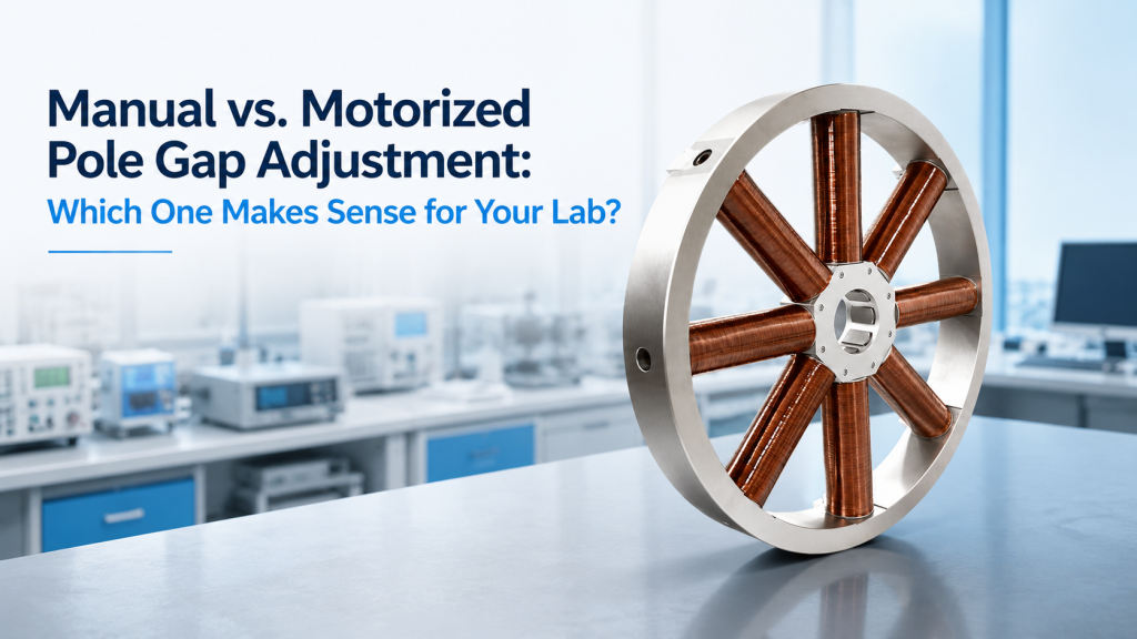
When buyers select an electromagnet, they usually focus on magnetic field strength, pole diameter, field uniformity, cooling, and power supply rating.
Pole gap adjustment often receives less attention.
But once a laboratory needs to test samples of different sizes, install a cryostat, change optical accessories, or automate repeated experiments, the adjustment method becomes a real procurement decision:
Should the electromagnet use manual or motorized pole gap adjustment?
Manual adjustment is simpler, less expensive, and often completely adequate for laboratories that change the gap only occasionally.
Motorized adjustment can improve repeatability, remote operation, workflow automation, and operator safety in systems that require frequent gap changes. However, it also introduces motors, encoders, controllers, interlocks, synchronization, maintenance, and additional acceptance requirements.
The right decision depends not on which option sounds more advanced, but on how the electromagnet will actually be used.
This article explains how to compare manual vs. motorized pole gap adjustment and what buyers should confirm before ordering a custom electromagnet.
1. What Pole Gap Adjustment Actually Changes
The pole gap is the working distance between the opposing electromagnet pole faces.
It determines how much space is available for:
- Samples
- sample holders
- Hall probes
- cryostats
- optical windows
- microscope objectives
- rotation stages
- electrical contacts
- cable routing
- temperature-control hardware
- field verification probes
The pole gap also affects magnetic performance.
For a given electromagnet and pole-cap configuration, increasing the gap generally reduces the achievable magnetic field, while reducing the gap generally increases magnetic efficiency. A Lake Shore electromagnet manual explicitly describes this relationship and instructs users to adjust the gap only after reducing current to zero and switching off the power supply.
Pole gap adjustment is therefore not merely a mechanical convenience.
Every new gap can change:
- Maximum field
- field-current relationship
- field uniformity
- fringe field
- sample position
- power requirement
- acceptance basis
2. Manual vs. Motorized Pole Gap Adjustment at a Glance
Manual Pole Gap Adjustment
The operator changes the gap using:
- Handwheels
- lead screws
- rotating handles
- locking levers
- removable spacers
- indexed mechanical positions
- shims or calibrated blocks
The operator measures the gap, aligns the poles, and locks them in position.
Motorized Pole Gap Adjustment
One or more motors move the poles under electronic control.
The system may include:
- Stepper motors
- servo motors
- gearboxes
- encoders
- limit switches
- brakes
- motion controllers
- software commands
- safety interlocks
- synchronized left-right movement
- stored gap positions
Motorized adjustment can be controlled from a local panel, computer, API, or automated test sequence.
3. Manual Adjustment Is Often the Sensible Default
Manual adjustment should not be viewed as an inferior option.
It is often the most practical solution when:
- The gap changes only occasionally.
- Only one or two sample fixtures are used.
- The electromagnet is operated by trained laboratory staff.
- Remote adjustment is not required.
- Adjustment speed is not critical.
- The required gap can be measured easily.
- Procurement budget is limited.
- Long-term mechanical simplicity is valued.
For many university laboratories, a gap may remain unchanged for weeks or months.
In that situation, adding motorized positioning may increase cost and complexity without improving the actual experiment.
4. When Motorized Adjustment Starts to Make Sense
Motorized pole gap adjustment becomes more valuable when the gap is a recurring experimental variable rather than a one-time setup dimension.
Typical situations include:
- Frequent sample changes
- automated production testing
- multiple cryostat or fixture sizes
- remote operation
- restricted access around the magnet
- high-throughput sensor testing
- software-controlled experimental sequences
- repeated measurements at predefined gaps
- formal positioning repeatability requirements
- hazardous or inconvenient operator access
- integration into a larger automated platform
If technicians must stop an automated test, enter the magnet area, turn two handwheels, measure the gap, lock both poles, and restart the system several times per day, motorization may provide real value.
5. Adjustment Frequency Is the First Decision Question
The simplest decision factor is:
How often will the pole gap actually change?
Occasional Adjustment
Examples:
- During initial installation
- when changing between two major accessories
- once per research campaign
- several times per year
Manual adjustment is usually sufficient.
Regular Adjustment
Examples:
- Several times per week
- whenever a new sample holder is installed
- during repeated cryostat changes
- as part of a standardized test workflow
Manual adjustment may still work, but indexed or motor-assisted adjustment becomes attractive.
High-Frequency Adjustment
Examples:
- Several times per shift
- automated test recipes
- unattended operation
- multiple gap conditions in one measurement sequence
Motorized adjustment is more likely to justify its cost.
6. Manual Adjustment Can Still Be Highly Repeatable
Manual does not necessarily mean imprecise.
A well-designed manual system may use:
- Fine-pitch lead screws
- calibrated scales
- digital indicators
- mechanical stops
- indexed positions
- gauge blocks
- symmetric adjustment mechanisms
- backlash-control procedures
- rigid locking systems
Some electromagnets use repeatable indexed gap positions rather than fully continuous adjustment. Lake Shore, for example, documents an indexed-gap mechanism with six repeatable positions intended to simplify reconfiguration. That is a manufacturer-specific design, but it demonstrates an important middle option between basic manual adjustment and full motorization.
For laboratories that use a small number of standard gap settings, an indexed manual mechanism may be more useful than a continuously adjustable motorized system.
7. Continuous Adjustment vs. Indexed Adjustment
Buyers should distinguish between two different requirements.
Continuous Adjustment
The gap can be set anywhere within a permitted range.
Example:
- Any setting between 20 mm and 100 mm
This provides flexibility but requires a reliable measurement method and position control.
Indexed Adjustment
The gap can be set at specific predefined positions.
Example:
- 20 mm
- 30 mm
- 40 mm
- 50 mm
- 70 mm
- 100 mm
Indexed settings can offer:
- Easier repeatability
- faster setup
- fewer measurement errors
- simpler calibration records
- lower cost than full motorization
A laboratory that always uses 30 mm and 60 mm gaps may not benefit from infinitely variable movement.
8. Motorized Does Not Automatically Mean More Accurate
A motor only creates motion.
It does not automatically guarantee accurate gap positioning.
A motorized system must still define:
- Position resolution
- minimum movement
- absolute accuracy
- unidirectional repeatability
- bidirectional repeatability
- backlash
- load capacity
- speed
- travel range
- encoder location
- homing method
- locking behavior
Newport’s motorized positioning guidance treats travel, minimum incremental motion, repeatability, accuracy, speed, and load capacity as separate selection parameters. The same distinction should be applied to motorized magnet poles: a small commanded step is not automatically equal to accurate physical positioning.
9. Resolution, Accuracy, and Repeatability Are Different
These terms are frequently confused.
Resolution
The smallest position increment the controller can command or display.
Accuracy
How close the actual gap is to the commanded gap.
Repeatability
How closely the mechanism returns to the same position after moving away and coming back.
Backlash
Lost motion or position difference caused by reversing the direction of a screw or gear mechanism.
A system may display a gap of 40.000 mm but physically be at 40.2 mm.
It may also return consistently to 40.2 mm every time. That would indicate good repeatability but imperfect absolute accuracy.
Buyers should specify which characteristic matters.
10. Why Backlash Matters in Pole Adjustment
Lead screws, gears, and mechanical drives may have backlash.
When motion direction reverses, the commanded movement may begin before the pole physically moves.
Backlash can affect:
- Final gap value
- left-right symmetry
- return-to-position repeatability
- calibration records
- automated sequences
- field reproducibility
A documented manual electromagnet procedure recommends approaching the final gap from a defined direction to remove lead-screw backlash before locking the poles. It also warns that magnetic attraction can create significant forces between the poles at high field.
A motorized mechanism also needs a backlash strategy, such as:
- Always approaching from one direction
- encoder feedback at the moving pole
- backlash compensation
- preloading
- direct-drive actuators
- mechanical locking after positioning
11. Two Poles Must Move Symmetrically
Many variable-gap electromagnets have two movable poles.
The sample should normally remain centered between them.
If one pole moves more than the other:
- The gap center shifts.
- The sample may no longer be at the magnetic center.
- Optical alignment may change.
- Cryostat clearance may become unequal.
- Field uniformity may change.
- Fixture interference may occur.
A manual system may use separate handwheels, requiring the operator to measure both sides.
A motorized system may use:
- Two synchronized motors
- one motor with mechanical linkage
- dual encoders
- master-slave control
- center-position feedback
Motorized adjustment should not be judged only by total gap readout.
Buyers should also ask how pole symmetry is maintained.
12. Center-Preserving Motion Is Often More Important Than Speed
Suppose a 50 mm gap is changed to 70 mm.
There are at least two ways to do it:
One-Sided Motion
One pole remains fixed while the other moves 20 mm.
The magnetic center shifts by approximately 10 mm.
Symmetric Motion
Both poles move outward by 10 mm.
The magnetic center remains approximately fixed.
For experiments involving:
- Cryostats
- optical paths
- microscope objectives
- Hall fixtures
- fixed sample stages
- calibrated sensor positions
center-preserving adjustment is usually more useful.
This requirement should be stated explicitly.
13. Magnetic Pull Force Changes the Mechanical Problem
Opposing magnet poles attract each other when the electromagnet is energized.
At high field and small gap, the mechanical force can be substantial.
The adjustment system must therefore resist:
- Pole attraction
- movement under magnetic load
- screw deflection
- frame deformation
- motor back-driving
- loss of position
- vibration
- unintended closing of the gap
This is why variable-gap electromagnets commonly use mechanical pole locks.
A motorized system may also need:
- Brakes
- self-locking screws
- mechanical clamps
- safety stops
- load-rated gearboxes
- fail-safe holding mechanisms
The motor should not be the only component preventing the poles from moving.
14. Should Adjustment Be Allowed While the Magnet Is Energized?
For most laboratory electromagnets, the conservative approach is:
- Ramp current to zero.
- Disable the power supply.
- Confirm safe status.
- Adjust the gap.
- Lock the poles.
- Verify clearance.
- Re-energize the magnet.
This avoids adjustment under magnetic attraction and reduces the risk of trapping samples, damaging fixtures, or changing geometry during a measurement.
A motorized mechanism may tempt buyers to request live adjustment under field.
That should not be assumed safe or supported.
If energized adjustment is genuinely required, the project needs a dedicated engineering review covering:
- Magnetic forces
- motor torque
- structural loading
- motion stability
- control failure
- collision risk
- field changes during motion
- emergency stop behavior
- personnel access
For most research laboratories, motorized adjustment should still occur at zero current.
15. Manual Adjustment Has a Clear Safety Advantage
Manual mechanisms can be simple to understand.
The operator can see:
- Pole movement
- sample clearance
- fixture position
- cable routing
- mechanical interference
There are fewer hidden failure modes from:
- Software commands
- motor-controller faults
- encoder errors
- limit-switch failures
- unintended remote operation
However, manual operation can still be unsafe if:
- The magnet remains energized.
- hands enter a pinch zone.
- heavy poles move unexpectedly.
- locking levers are not secured.
- the sample holder is trapped.
- both poles are not adjusted evenly.
Manual systems still need procedures, labels, and mechanical stops.
16. Motorized Adjustment Requires More Safety Logic
A motorized system may need:
- Current-zero confirmation
- power-supply disable input
- motion-enable interlock
- travel limit switches
- software travel limits
- hardware end stops
- over-torque detection
- obstacle detection
- emergency stop
- local motion controls
- remote-motion warning
- pole-lock status
- homing procedure
- communication-loss behavior
A safe sequence may be:
- Stop the experiment.
- Ramp magnet current to zero.
- Disable power output.
- Confirm zero-current status.
- Unlock the poles, if locking is powered.
- Move both poles to the commanded position.
- Confirm encoder positions.
- Lock the poles.
- Verify gap and clearance.
- Enable magnetic operation.
This sequence should be agreed before PO.
17. Motor and Encoder Performance Near a Magnet Must Be Evaluated
A motorized actuator installed near an electromagnet may operate in a fringe magnetic field.
Depending on design, the field could affect:
- Motor behavior
- magnetic encoders
- limit switches
- cables
- nearby electronics
- position sensors
The solution may involve:
- Locating motors farther from the poles
- using mechanical extension shafts
- selecting suitable encoder technology
- shielding sensitive electronics
- defining a safe fringe-field limit
- verifying performance at maximum field
This is a custom integration question.
A standard motion stage should not automatically be assumed suitable next to a high-field electromagnet.
18. Motorized Adjustment Can Introduce Measurement Noise
Motorized mechanisms can add:
- Electrical switching noise
- ground loops
- motor-drive noise
- cable motion
- vibration
- heat
- electromagnetic interference
For sensitive Hall, transport, optical, or low-noise measurements, the motor should normally stop before data acquisition.
The control system may also need to:
- Disable motor current after positioning
- isolate motor electronics
- wait for vibration to settle
- confirm locking before measurement
- separate motor cables from signal cables
Motorization should improve workflow without becoming a new noise source.
19. Manual Adjustment Is Easier to Maintain
A manual adjustment mechanism may require only:
- Cleaning
- lubrication
- screw inspection
- lock inspection
- scale verification
- occasional alignment checks
A motorized system may additionally require:
- Motor maintenance
- gearbox inspection
- encoder checks
- limit-switch checks
- controller backups
- firmware support
- cable replacement
- software compatibility
- position recalibration
- spare-part planning
For equipment expected to remain in service for ten or fifteen years, maintainability matters.
A motorized design should use components that can be serviced or replaced.
20. Motorized Adjustment Adds Software Dependency
A motorized gap may be controlled through:
- Local touchscreen
- PLC
- PC software
- SCPI commands
- custom API
- LabVIEW
- Python
- Ethernet or serial interface
Buyers should ask:
- Can the gap be adjusted without a PC?
- Is local manual control available?
- Can the position be read remotely?
- Are commands documented?
- Can stored positions be recalled?
- What happens if software crashes?
- What happens after power loss?
- Is homing required after restart?
- Can configuration files be backed up?
- Is offline operation supported?
The ability to move a pole should not disappear because one computer is replaced.
21. Position Feedback Should Be Defined Clearly
Motorized adjustment may use:
Open-Loop Step Counting
The controller estimates position from motor steps.
Advantages:
- Simpler
- lower cost
Risks:
- Lost steps may create position error.
- Actual pole movement is not independently verified.
Motor-Shaft Encoder
An encoder measures motor or screw rotation.
Advantages:
- Better feedback than open loop
Risk:
- It may not directly measure the pole position after backlash or mechanical compliance.
Direct Linear Encoder
An encoder measures the moving pole or carriage directly.
Advantages:
- Better representation of actual position
- improved repeatability and fault detection
Cost and integration complexity are higher.
For high-precision automated gaps, direct position feedback is usually more meaningful than motor-step count alone.
22. Mechanical Locking After Motion
Once the desired gap is reached, the poles must remain stable.
Possible methods include:
- Manual locking levers
- motor-driven clamps
- self-locking lead screws
- mechanical brakes
- hydraulic or pneumatic locks
- indexed locking pins
A system can be motorized but still require manual locking.
That hybrid approach may be acceptable when adjustments are infrequent but heavy manual motion is undesirable.
For fully remote operation, both movement and locking may need automation.
23. A Hybrid System May Be the Best Choice
The real choice is not always purely manual or fully motorized.
A hybrid system may use:
- Motor-assisted movement
- manual fine adjustment
- digital gap display
- manual locking
- indexed mechanical positions
- powered coarse adjustment
- stored mechanical stops
- motorized one-axis sample stage with manual pole gap
Hybrid solutions can provide much of the practical benefit without the cost and risk of a fully automated mechanism.
The correct configuration depends on what problem the buyer is trying to solve.
24. Manual Adjustment for Cryostat Integration
A laboratory may use one electromagnet with several cryostats.
Manual adjustment can work when:
- Cryostats are changed infrequently.
- Each cryostat has a documented required gap.
- Operators can measure both sides safely.
- Sample center alignment is checked after installation.
- There is enough physical access for handwheels.
- Gap changes are made only at zero current.
Useful features may include:
- Indexed cryostat-specific gap settings
- removable spacers
- digital indicators
- mechanical stops
- alignment reference marks
- a written setup checklist
For occasional cryostat changes, these features may be more valuable than full motorization.
25. Motorized Adjustment for Automated Sample Platforms
Motorization becomes more attractive when the electromagnet is part of an automated platform.
Examples include:
- Multiple sample carriers
- robotic sample exchange
- production sensor testing
- automated calibration
- recipe-based operation
- remote facility use
- restricted-access enclosures
The test recipe may contain:
- Required gap
- pole-cap configuration
- current limit
- field calibration file
- sample-holder type
- maximum allowed field
- safety checks
In this case, gap position becomes part of the test configuration rather than a manual setup note.
26. Gap Changes May Require New Field Calibration
A different pole gap changes the relationship between current and magnetic field.
Therefore, the system may need a separate:
- Field-current curve
- maximum-current limit
- field uniformity record
- calibration table
- software configuration
- acceptance report
Do not assume one calibration curve applies to every gap.
Even if the motion system returns accurately to a previous gap, field performance should be characterized under the defined configuration.
27. When Recalibration May Be Reduced
Recalibration effort may be reduced when the system uses:
- Repeatable indexed positions
- stable pole-cap geometry
- reliable locking
- defined approach direction
- verified mechanical repeatability
- stored field-current tables
- field sensor feedback
- closed-loop field control
Some commercial electromagnets use indexed positions specifically to improve repeatable reconfiguration. However, whether recalibration can be avoided depends on the complete system and acceptance requirement, not merely the presence of an index.
For formal calibration work, the buyer should define how performance will be verified after each gap change.
28. Closed-Loop Field Control Does Not Eliminate Gap Concerns
A field sensor and closed-loop controller can correct the center field after a gap change.
But closed-loop control does not automatically correct:
- Field uniformity
- transverse field components
- sample misalignment
- pole asymmetry
- reduced maximum field
- changed fringe field
- cryostat clearance
- mechanical interference
Closed-loop control can regulate a measured point.
It cannot make every mechanical configuration magnetically equivalent.
29. Gap Readout Should Match the Real Definition
Buyers should define exactly what the displayed gap means.
Possibilities include:
- Pole-face-to-pole-face distance
- pole-core position
- actuator displacement
- distance between mechanical reference surfaces
- nominal indexed setting
For tapered or specially shaped pole caps, the relevant working gap is normally the shortest operating distance between the pole faces at the measurement region.
The gap display should not be based on an unrelated actuator coordinate unless the conversion is documented.
30. Left and Right Pole Position Should Be Available Separately
A single total-gap value may hide asymmetry.
A better motorized interface may display:
- Left pole position
- right pole position
- total gap
- calculated center offset
- lock status
- limit status
- homing status
- motion fault
This helps diagnose:
- Lost motion
- uneven pole movement
- encoder problems
- mechanical obstruction
- center shift
For high-value automated systems, separate position feedback can be more useful than one combined number.
31. Speed Is Usually Less Important Than Controlled Motion
Pole gap adjustment rarely needs extreme speed.
More important requirements are:
- Smooth movement
- adequate torque
- controlled acceleration
- low overshoot
- synchronized poles
- reliable stopping
- collision prevention
- stable final position
Fast motion can increase:
- Impact risk
- vibration
- overshoot
- sample damage
- pinch hazard
A slower, controlled mechanism may be more suitable for heavy magnet poles.
32. Large Electromagnets Change the Decision
As electromagnet size increases, manual adjustment becomes more demanding.
Large poles may require:
- Greater mechanical force
- longer adjustment time
- access from both sides
- multiple operators
- special tools
- stronger locking mechanisms
Motorization may reduce physical effort.
However, a large system also requires:
- Higher-capacity actuators
- stronger brakes
- structural analysis
- more serious safety systems
- emergency controls
- maintenance access
Motorization becomes more valuable and more complex at the same time.
33. Accessibility Matters
Manual adjustment may be inconvenient when the electromagnet is:
- Inside a safety enclosure
- beneath an optical table
- integrated with a cryostat
- surrounded by optical hardware
- mounted in a production line
- located in a restricted area
- operated remotely
If operators cannot reach the handwheels without disturbing other equipment, motorization may prevent repeated realignment.
The laboratory layout should be reviewed before the adjustment method is selected.
34. Manual Adjustment May Be Better for Optical Stability
In an optical experiment, the pole gap may be set once during alignment and then left unchanged.
Manual adjustment can be preferable because it avoids:
- Motors near the optical path
- controller cables
- motor vibration
- additional heat
- accidental remote movement
- more complex mechanical structures
For a MOKE or photoluminescence setup that uses one fixed cryostat, a rigid manually locked gap may be the more stable and economical choice.
35. Motorized Adjustment May Be Better for Repetitive Fixture Changes
A sensor-testing laboratory may use many fixtures with known sizes.
For example:
- Fixture A: 25 mm gap
- Fixture B: 40 mm gap
- Fixture C: 65 mm gap
A motorized or indexed system can:
- Recall predefined positions
- reduce operator setup time
- standardize workflows
- prevent unauthorized gap settings
- apply gap-specific current limits
- select the correct calibration file
- record the gap in test logs
In this case, motorization supports process control, not merely convenience.
36. Motorized Adjustment Should Be Linked to Current Limits
A wider gap may require more current to produce the same field.
But the magnet may have a different safe or achievable operating range at each gap.
The control system may need:
- Gap-dependent current limits
- gap-dependent field limits
- calibration-table selection
- cooling checks
- warning messages
- recipe validation
For example, the software should not assume that a field available at a 20 mm gap is also available at an 80 mm gap.
A smart motorized system should link mechanical position to magnetic operating limits.
37. Gap Adjustment and Pole-Cap Changes Are Different Functions
Changing the gap does not change the pole-face geometry.
Changing pole caps may affect:
- Pole-face diameter
- maximum field
- field uniformity
- optical access
- sample clearance
- saturation
- calibration
Buyers should clarify whether they need:
- Variable pole gap
- replaceable pole caps
- both
- neither
A motorized gap cannot replace the need for different pole caps when the experiment requires another field profile or optical geometry.
38. Manual vs. Motorized Pole Gap Adjustment Cost
Manual adjustment usually requires:
- Mechanical screws
- handles
- scales
- locks
- stops
Motorized adjustment may additionally require:
- Motors
- encoders
- gearboxes
- controllers
- cables
- software
- limit switches
- interlocks
- brakes
- enclosure changes
- additional FAT
- documentation
- future spare parts
The cost comparison should include more than initial hardware.
Consider:
- Engineering integration
- commissioning
- maintenance
- software support
- downtime risk
- operator labor
- future replacement parts
Motorization is valuable when the operational benefit exceeds the additional lifecycle cost.
39. FAT Requirements for Manual Adjustment
A manual pole-gap FAT may verify:
- Minimum and maximum gap
- adjustment smoothness
- pole symmetry
- scale or indicator accuracy
- locking function
- mechanical stops
- backlash-control method
- repeatability at standard gaps
- sample clearance
- field performance at agreed gaps
The report should state how the gap was measured.
Possible tools include:
- Caliper
- micrometer
- digital indicator
- gauge blocks
- laser measurement
- calibrated spacer
40. FAT Requirements for Motorized Adjustment
Motorized systems require additional tests.
Possible FAT items include:
- Homing
- minimum and maximum travel
- commanded-position accuracy
- repeatability
- bidirectional positioning
- left-right synchronization
- center offset
- limit switches
- hardware stops
- emergency stop
- communication-loss behavior
- current-zero interlock
- lock confirmation
- gap-dependent current limit
- local and remote control
- position logging
- recovery after power interruption
A motorized gap should be accepted as a motion-control subsystem, not only as a moving magnet part.
41. Practical Decision Guide
Choose Manual Adjustment When
- Gap changes are rare.
- The magnet is easily accessible.
- Trained users operate the system.
- Budget is limited.
- A small number of standard gaps is sufficient.
- Remote operation is unnecessary.
- Optical or low-noise simplicity is important.
- Maintenance resources are limited.
Choose Indexed Manual Adjustment When
- Several repeatable gaps are used.
- Fast reconfiguration is helpful.
- Continuous positioning is unnecessary.
- Repeatability matters more than automation.
- A lower-cost middle option is preferred.
Choose Motorized Adjustment When
- Gap changes are frequent.
- Automated recipes are required.
- Remote operation is required.
- The magnet is difficult to access.
- Heavy poles make manual movement impractical.
- Position logging is required.
- Gap-dependent safety limits are needed.
- The system is part of a larger automated platform.
Choose a Hybrid System When
- Powered movement is useful.
- Manual locking is acceptable.
- Only coarse motion needs automation.
- The laboratory wants easier adjustment without full software dependence.
42. Questions Buyers Should Answer Before Requesting a Quote
Experiment
- How many different gap settings are required?
- How often will the gap change?
- Must the sample remain at a fixed magnetic center?
- Is a cryostat or optical accessory involved?
- Is adjustment needed during a test sequence?
- Is remote operation required?
Magnetic Performance
- Required field at each gap:
- uniformity volume at each gap:
- pole-cap type:
- maximum current:
- field calibration method:
- open-loop or closed-loop operation:
Mechanical Requirements
- Minimum gap:
- maximum gap:
- continuous or indexed movement:
- required positioning accuracy:
- required repeatability:
- allowable center shift:
- pole-locking method:
- available installation space:
Control and Safety
- Local or remote control:
- SCPI or API:
- current-zero interlock:
- emergency stop:
- limit switches:
- position feedback:
- power-loss behavior:
- gap-dependent current limits:
- motion logging:
Acceptance
- Gap measurement method:
- positioning repeatability test:
- number of test cycles:
- field test at each gap:
- uniformity mapping:
- report format:
- FAT or SAT responsibility:
These answers allow the supplier to recommend the right adjustment architecture.
43. Better RFQ Examples
Weak RFQ
“We need an electromagnet with an adjustable pole gap.”
This does not explain how the adjustment will be used.
Better RFQ for Manual Adjustment
“We require an electromagnet with a manually adjustable pole gap from 20 mm to 80 mm. The gap will normally be changed less than once per month. Both poles should move symmetrically to keep the sample center fixed. Please include mechanical locking, a readable gap scale, and repeatable reference positions at 20, 40, 60, and 80 mm.”
Better RFQ for Motorized Adjustment
“We require motorized symmetric pole gap adjustment from 20 mm to 100 mm. The system will use automated test recipes and must return to predefined gap positions with documented repeatability. Motion shall be permitted only when magnet current is zero and output is disabled. Please include independent pole-position feedback, hardware travel limits, emergency stop, gap logging, local control, and a documented remote-control interface.”
These two RFQs describe very different products.
44. Common Buyer Mistakes
Mistake 1: Choosing Motorized Because It Sounds More Advanced
Automation should solve a real workflow problem.
Mistake 2: Assuming Manual Means Inaccurate
A rigid indexed or measured manual system may be highly repeatable.
Mistake 3: Comparing Only Position Resolution
Resolution is not the same as accuracy or repeatability.
Mistake 4: Ignoring Pole Symmetry
The total gap may be correct while the sample center has shifted.
Mistake 5: Adjusting Under Magnetic Field
Gap adjustment should normally be performed at zero current unless the system is specifically engineered for energized motion.
Mistake 6: Forgetting Mechanical Locks
The actuator should not be assumed to hold the poles safely under magnetic force without a defined locking method.
Mistake 7: Using One Field Calibration for Every Gap
Field-current behavior changes with gap.
Mistake 8: Ignoring Motor Noise and Fringe Field
Motors, encoders, and cables may affect sensitive experiments or behave differently near the electromagnet.
Mistake 9: Not Testing Motion During FAT
A motorized mechanism requires its own measurable acceptance criteria.
45. How Cryomagtech Supports Custom Pole Gap Configuration
Cryomagtech supplies custom electromagnets, excitation power supplies, field probes, control software, cooling configurations, and integrated Magnet & Field Systems for research and industrial testing.
For variable pole gap electromagnet projects, we help evaluate:
- Manual, indexed, hybrid, or motorized adjustment
- minimum and maximum pole gap
- symmetric pole movement
- sample-center preservation
- positioning accuracy and repeatability
- backlash and locking
- cryostat and optical-access requirements
- pole-gap-dependent field performance
- field-current calibration at multiple gaps
- gap-dependent current limits
- local and remote controls
- safety interlocks
- FAT and acceptance requirements
- realistic cost and maintenance trade-offs
The most advanced pole-gap mechanism is not automatically the best one.
The right solution is the simplest mechanism that can meet the laboratory’s real adjustment frequency, repeatability, safety, automation, and magnetic-performance requirements.
References
- Lake Shore Cryotronics – EM4-HVA Electromagnet User Manual
https://www.lakeshore.com/docs/default-source/product-downloads/manuals/em4-hva_manual.pdf - Lake Shore Cryotronics – EM-V Series Electromagnets
https://www.lakeshore.com/docs/default-source/default-document-library/em47vcatalog.pdf - Newport – Motorized Linear Stage Selection Guide
https://www.newport.com/medias/sys_master/resources/h63/h54/9954238234654/Motion-Control-Linear-Stages-Newport-2018/Motion-Control-Linear-Stages-Newport-2018.pdf
Key Takeaways
- Manual vs. motorized pole gap adjustment should be decided by actual laboratory workflow, not by which option sounds more advanced.
- Manual adjustment is usually suitable when gap changes are infrequent and trained operators can access the magnet safely.
- Indexed manual adjustment can provide repeatable standard gaps without the cost and complexity of full automation.
- Motorized adjustment is most valuable for frequent changes, remote operation, automated recipes, heavy poles, or restricted-access systems.
- Resolution, accuracy, repeatability, and backlash are different positioning specifications.
- Both poles may need to move symmetrically to preserve the magnetic center.
- Pole movement should normally occur only after current is reduced to zero and the power supply is disabled.
- Motors, encoders, controllers, locks, limits, interlocks, and software all become part of the motorized system.
- A different pole gap may require a different field-current calibration, field limit, and uniformity record.
- Motorized pole gap adjustment should have measurable FAT criteria covering positioning, synchronization, safety, recovery, and field performance.
For electromagnet procurement, the key question is not only:
“Can the pole gap be adjusted?”
The better question is:
“How often must it move, how accurately must it return, how will the magnetic center be preserved, and how will the system prevent unsafe movement?”