
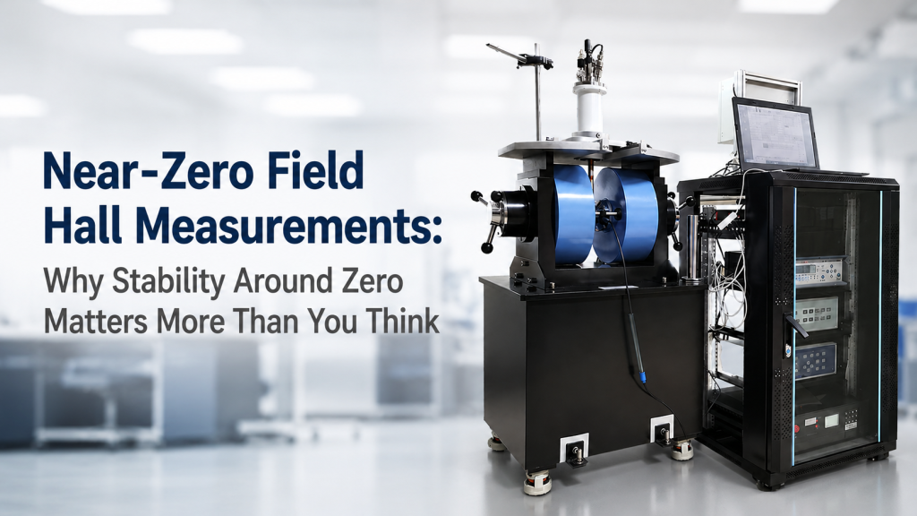
In Hall effect measurements, users often focus on high magnetic field.
That makes sense. A stronger magnetic field can increase Hall voltage and make the signal easier to measure.
But for many research applications, the most difficult part of the measurement is not the high-field region.
It is the near-zero field region.
Near-zero field Hall measurements can be affected by residual magnetization, field offset, power supply zero drift, background magnetic field, contact asymmetry, thermoelectric voltage, low-field noise, and measurement timing. These effects may be small compared with a 1 T field, but they can become critical when the measurement depends on behavior near zero.
This article explains why stability around zero matters in Hall measurements, what can go wrong, and what buyers should consider when choosing a Hall effect measurement system, electromagnet, and control power supply.
1. What “Near-Zero Field” Means in Hall Measurements
Near-zero field does not always mean exactly 0 T.
It may refer to a small field region around zero, such as:
- -10 mT to +10 mT
- -1 mT to +1 mT
- -100 µT to +100 µT
- the zero-crossing region during field reversal
- the low-field part of a Hall sweep
- the field region used to evaluate offset or linearity
For some samples, the low-field slope is used to extract transport information. For others, the near-zero region is used to check symmetry, offset, or carrier behavior.
NIST describes Hall measurement as a technique for determining carrier density and mobility in semiconductor materials, and also highlights practical sources of Hall measurement error such as contact quality, current reversal equilibrium, visible sample damage, light exposure, and sample temperature uniformity.
That is why near-zero field behavior should not be ignored.
2. Why High-Field Performance Does Not Guarantee Good Near-Zero Performance
A system may perform well at high field but still be difficult near zero.
At high field, the Hall signal may be large enough to dominate small offsets.
Near zero, the signal becomes smaller, and unwanted effects become more visible.
Common Near-Zero Problems
Near-zero Hall data may be affected by:
- Magnet remanence
- current source offset
- power supply zero drift
- background magnetic field
- field sensor offset
- contact asymmetry
- longitudinal voltage mixing
- thermal EMF
- voltage noise
- sample heating
- insufficient settling time after field reversal
A smooth high-field sweep does not prove the zero region is clean.
For research-grade Hall data, the zero-crossing region deserves special attention.
3. Residual Magnetization: The Magnet May Not Be Truly at Zero
Electromagnets with ferromagnetic cores can retain residual magnetization after current is reduced to zero.
This means:
- Power supply current may be 0 A.
- The magnetic field may not be 0 T.
- The sample may still experience a residual field.
- The next sweep may depend on field history.
This is related to magnetic hysteresis, where magnetic material behavior depends on previous magnetic history. Magnetic hysteresis is commonly described as a memory effect in magnetic materials.
For near-zero Hall measurements, this matters because the user may think the system is at zero field when the sample is still exposed to a small residual field.
4. Current Zero Is Not Always Field Zero
A very common misunderstanding is:
“If the magnet current is zero, the magnetic field is zero.”
This is not always true.
For an air-core Helmholtz coil, field is usually closely related to current, assuming the background field is known.
For an electromagnet with an iron core, residual magnetization can create field even when the coil current is zero.
For low-field measurements, the difference between current zero and field zero can matter.
Practical Example
A Hall measurement system may sweep from positive field to negative field.
At the commanded zero-current point, the actual magnetic field may still be slightly positive or negative due to remanence.
If the software assumes that point is exactly zero, the low-field slope or offset correction may be wrong.
5. Zero Drift in the Power Supply
The power supply also matters.
A Hall measurement system often needs a stable excitation source for the magnet.
At high current, a small zero offset may not be important.
Near zero, it can be significant.
Power Supply Issues Around Zero
Buyers should consider:
- Current offset
- zero-crossing stability
- bipolar output behavior
- output resolution near zero
- current ripple
- current drift
- polarity transition behavior
- control loop behavior near zero
- digital-to-analog control resolution
- output noise floor
A power supply that is acceptable for high-field exposure may not be ideal for low-field Hall measurements.
Near-zero stability is a real performance requirement.
6. Bipolar Control: Necessary, but Not Enough
Near-zero Hall measurements often require bipolar magnetic field control.
A bipolar power supply can drive positive and negative current, allowing the magnet field to reverse direction.
This is important for:
- Hall voltage sign check
- field reversal
- offset reduction
- carrier type confirmation
- low-field slope extraction
- hysteresis and symmetry studies
- magnetoresistance comparison
- weak-signal transport measurements
But bipolar output alone is not enough.
The system must also handle:
- smooth zero crossing
- stable low-current output
- safe reversal under inductive load
- controlled ramp rate
- enough settling time
- correct synchronization with voltage measurement
- predictable field-current relationship around zero
A bipolar supply that reverses current too abruptly, drifts around zero, or produces noise during polarity transition can create measurement problems.
7. Remanence and Demagnetization Procedures
For electromagnets, remanence may need to be managed.
Possible strategies include:
- Measuring residual field
- using a field probe for verification
- applying a degaussing sequence
- using a defined approach direction for low-field points
- recording field history
- using a correction table
- avoiding assumptions based only on current setpoint
A degaussing or demagnetizing procedure may reduce residual field, but it should be defined and repeatable.
Important Point
Do not treat “zero field” as a default state.
For near-zero measurements, zero field may need to be actively established, measured, or corrected.
8. Background Magnetic Field Can Be Larger Than the Target Region
Near-zero Hall measurements may be affected by background magnetic field.
This can come from:
- Earth’s magnetic field
- building steel
- nearby magnets
- power cables
- motors
- pumps
- lab benches
- steel tools
- elevators
- magnetic sample holders
- current loops
If the target near-zero region is only a few millitesla, or even microtesla-level, the laboratory background field can become relevant.
For air-core coil systems, the background field may be compensated or subtracted.
For electromagnets, the background field is usually smaller compared with high-field operation, but it can still affect very low-field data.
9. Hall Voltage Offset Around Zero
The measured Hall voltage may include more than the true Hall signal.
It may include:
- Offset voltage
- thermoelectric voltage
- contact asymmetry
- longitudinal voltage contamination
- instrument offset
- noise pickup
- sample heating effects
NIST’s resistivity and Hall measurement page gives formulas for Hall-related quantities and discusses how Hall mobility and carrier density are derived from Hall and resistivity measurements.
If the near-zero voltage contains offset components, the calculated result can become unreliable.
This is why field reversal, current reversal, and proper contact geometry are so important.
10. Contact Symmetry Matters More Near Zero
Near zero, contact-related errors can become more visible.
A Hall sample may have:
- imperfect contact placement
- non-ohmic contacts
- contact resistance imbalance
- damaged contact regions
- uneven current path
- sample thickness variation
- geometric asymmetry
These issues can mix longitudinal voltage into the Hall voltage.
When the true Hall voltage is small, this contamination can be significant.
A better magnet cannot fully compensate for poor Hall contact geometry.
For research-grade Hall data, sample preparation and contact verification must be part of the workflow.
11. Current Reversal and Field Reversal Help Separate Signals
Near-zero Hall measurements often benefit from reversal methods.
Sample Current Reversal
Reversing sample current can help reduce voltage offsets that do not change sign with current.
Magnetic Field Reversal
Reversing magnetic field can help separate Hall voltage from field-independent offsets.
Combined Reversal
Some measurement workflows use both sample current reversal and field reversal.
This can improve confidence, but it also adds complexity:
- More measurement states
- longer test time
- settling time after reversal
- synchronization requirements
- data processing logic
- possible thermal drift during sequence
Reversal methods are powerful only when the sequence is well controlled.
12. Settling Time Near Zero
After changing magnetic field, the system may need time to settle.
This is especially important around zero during field reversal.
Possible settling factors include:
- Coil inductance
- power supply control response
- magnet hysteresis
- sample voltage equilibrium
- instrument autoranging
- thermal drift
- software delay
- contact capacitance
- filtering
NIST’s Hall measurement error checklist specifically asks whether voltages reach equilibrium quickly after current reversal, noting that there may be delay for some materials.
If data is recorded too soon after reversal, the near-zero point may reflect transient behavior rather than true steady-state response.
13. Low-Field Noise Can Distort the Slope
Many Hall measurements rely on the slope of Hall voltage versus magnetic field.
Near zero, the slope may be sensitive to noise.
Noise sources may include:
- Power supply ripple
- voltage meter noise
- cable pickup
- grounding problems
- electromagnetic interference
- mechanical vibration
- temperature drift
- sample instability
- field sensor noise
- magnet current noise
If the low-field signal is small, noise can make the slope appear scattered or nonlinear.
A high-resolution data file does not automatically mean high-quality data.
The noise floor must be low enough for the measurement goal.
14. Field Resolution Is Not the Same as Field Stability
A system may allow very small field step settings in software.
For example:
- 0.1 mT step
- 0.01 mT step
- 1 µT step
But step resolution is not the same as stability.
Resolution Means
“How small a field increment can be commanded or displayed?”
Stability Means
“How much does the field actually change over time under the same setting?”
Near zero, stability may matter more than display resolution.
A system that can set 0.001 mT but drifts by 0.02 mT may not provide useful near-zero precision.
15. Electromagnet vs. Air-Core Coil Near Zero
Different field sources behave differently near zero.
Electromagnet
Advantages:
- Higher field possible
- compact high-field design
- useful for wide field sweeps
- suitable for many Hall systems
Near-zero challenges:
- remanence
- hysteresis
- field-current nonlinearity
- zero-field uncertainty
- degaussing requirement
- pole gap dependence
Air-Core Helmholtz Coil
Advantages:
- more linear field-current relationship
- lower remanence concern
- useful for low-field calibration
- open geometry
- good for Earth-field-level testing
Near-zero challenges:
- limited maximum field
- sensitivity to background field
- larger size for uniform volume
- lower field efficiency
- need for stable current source
For near-zero Hall measurements, the right choice depends on field range, sample needs, and whether low-field stability or high-field capability is more important.
16. Field Probe Placement Near Zero
If a field probe is used to verify near-zero field, its placement matters.
Ask:
- Is the probe at the sample position?
- Is the probe inside the same field region?
- Does the probe disturb the setup?
- Is the probe sensitive enough near zero?
- Is the probe calibrated for the range?
- Is the probe measuring the correct axis?
- Is the probe left in place during measurement or only used before testing?
A field reading away from the sample may not represent the field at the sample.
This is especially important in non-uniform fields or tight electromagnet gaps.
17. Near-Zero Field and Carrier Type Identification
Hall measurements are often used to determine carrier type.
The sign of the Hall coefficient can indicate whether electrons or holes dominate.
Near zero, sign errors may occur if:
- field polarity is wrong
- sample current polarity is wrong
- voltage leads are swapped
- residual field is not considered
- offset voltage dominates
- software sign convention is unclear
- field reversal is not verified
This is not rare.
A low-field sign error can lead to incorrect carrier type interpretation.
The measurement sequence and wiring convention should be documented.
18. Near-Zero Nonlinearity and Multi-Carrier Materials
Some materials may show non-simple Hall behavior.
Near-zero field may be important for identifying:
- multiple carrier transport
- electron-hole compensation
- weak localization-related behavior
- anomalous Hall components
- magnetic material effects
- low-field magnetoresistance
- nonlinear Hall response
For advanced research samples, the low-field region may contain useful physics.
In such cases, smoothing over the near-zero region or treating it as a nuisance can hide important information.
The measurement system should be stable enough not to confuse real sample behavior with instrument artifacts.
19. Temperature Dependence Near Zero
Temperature can make near-zero measurement more difficult.
Temperature changes may affect:
- carrier concentration
- mobility
- sample resistance
- contact resistance
- thermal EMF
- magnet coil resistance
- voltage drift
- instrument offset
- sample heating
For variable-temperature Hall systems, near-zero stability should be checked at relevant temperatures, not only at room temperature.
If the sample is measured at low temperature, contact stability and voltage settling can become even more important.
20. What Buyers Should Ask Before Choosing a Near-Zero Hall System
Buyers should define near-zero requirements clearly.
Magnetic Field Requirements
- Required field range:
- near-zero region of interest:
- field step size:
- field stability:
- bipolar operation required:
- field reversal required:
- degaussing required:
- residual field tolerance:
- field probe verification required:
Power Supply Requirements
- Current range:
- bipolar or unipolar:
- current resolution:
- zero-current offset:
- ripple and noise:
- current stability:
- ramp rate:
- zero-crossing behavior:
- communication interface:
- inductive load protection:
Hall Measurement Requirements
- Sample current range:
- current reversal required:
- field reversal required:
- voltage sensitivity:
- contact geometry:
- van der Pauw or Hall bar:
- temperature range:
- data export:
- raw data review:
- measurement sequence:
Environment Requirements
- Background field level:
- magnetic cleanliness:
- nearby motors or steel:
- cable routing:
- vibration sensitivity:
- thermal stability:
- light exposure control, if required:
This information helps the supplier recommend a realistic system.
21. Common Buyer Mistakes
Mistake 1: Assuming Zero Current Means Zero Field
This is not always true, especially for electromagnets with ferromagnetic cores.
Mistake 2: Focusing Only on Maximum Field
Maximum field does not prove near-zero stability.
Mistake 3: Ignoring Remanence
Residual field can affect low-field Hall data.
Mistake 4: Treating Software Step Size as Accuracy
Field resolution is not field stability or field accuracy.
Mistake 5: Measuring Too Soon After Reversal
Near-zero data may be distorted if field or voltage has not settled.
Mistake 6: Ignoring Contact and Thermal Offsets
A near-zero Hall signal can be overwhelmed by contact asymmetry and thermoelectric voltage.
Mistake 7: Not Recording Field History
For hysteretic magnets, previous field states may affect current low-field behavior.
22. Practical Near-Zero Measurement Checklist
Before running near-zero Hall measurements, check:
- Magnet degaussing or field history procedure
- field probe verification near zero
- current zero stability
- bipolar power supply behavior
- field reversal sequence
- sample current reversal sequence
- voltage settling time
- contact I-V linearity
- contact resistance balance
- background field measurement
- cable routing
- thermal stability
- raw data export
- sign convention
- data processing method
This checklist helps separate real material behavior from setup artifacts.
23. How Cryomagtech Supports Near-Zero Field Hall Measurement Projects
Cryomagtech supplies Hall effect measurement systems, electromagnets, Helmholtz coils, high-precision excitation power supplies, bipolar magnetic field drivers, field probes, and control software for material research and low-field measurement applications.
For near-zero Hall measurement projects, we help evaluate:
- Electromagnet or air-core coil selection
- bipolar power supply requirements
- residual field and degaussing considerations
- low-current stability
- field reversal sequence
- zero-crossing behavior
- field probe verification
- Hall measurement workflow
- sample current and field reversal
- voltage settling and timing
- low-noise wiring and cable routing
- acceptance criteria for near-zero operation
Near-zero performance is not a small detail.
For many Hall measurements, it is where the quality of the system becomes visible.
References
- NIST – Hall Effect Measurements Introduction
https://www.nist.gov/pml/nanoscale-device-characterization-division/popular-links/hall-effect/hall-effect-measurements-3 - NIST – Hall Effect Measurements: Sources of Error
https://www.nist.gov/pml/nanoscale-device-characterization-division/popular-links/hall-effect/resistivity-and-hall/hall - NIST – Resistivity and Hall Measurements
https://www.nist.gov/pml/nanoscale-device-characterization-division/popular-links/hall-effect/resistivity-and-hall - Wikipedia – Magnetic Hysteresis
https://en.wikipedia.org/wiki/Magnetic_hysteresis
Key Takeaways
- Near-zero field Hall measurements can be more difficult than high-field measurements.
- Zero current does not always mean zero magnetic field, especially in electromagnets with residual magnetization.
- Remanence, hysteresis, background field, power supply zero drift, contact asymmetry, and thermal EMF can affect low-field data.
- Bipolar power supply control is useful, but it must handle zero crossing, low-current stability, ramping, and settling time properly.
- Field resolution is not the same as field stability or field accuracy.
- Current reversal and field reversal can improve data quality when the measurement sequence is correctly controlled.
- Near-zero Hall data should be supported by clear field history, sign convention, voltage settling, and raw data review.
- Buyers should specify near-zero stability requirements, not only maximum magnetic field.
For Hall systems, the key question is not only:
“How high can the magnetic field go?”
The better question is:
“How stable, repeatable, and trustworthy is the system when the field passes through zero?”