In sensor calibration, material testing, and angular scanning experiments, one design question appears again and again:
“Should we rotate the device under test, or should we keep the device fixed and rotate the magnetic field?”
Both architectures are valid.
Rotating the DUT can be mechanically simple and intuitive. Rotating the magnetic field with a three-axis coil system can reduce mechanical movement and improve automation. But each approach creates different error sources, integration challenges, and cost implications.
This article explains how to choose between rotating the DUT and rotating the field, especially for magnetometer calibration, compass testing, IMU validation, magnetic material testing, and three-axis magnetic field platforms.
1. What Does “Rotating the DUT” Mean?
Rotating the DUT means the magnetic field stays fixed while the device under test physically changes orientation.
The DUT may be rotated using:
- Manual rotary stage
- Motorized turntable
- Two-axis goniometer
- Three-axis rotation platform
- Custom non-magnetic fixture
- Tilt and rotation mechanism
- Robotic positioning system
This architecture is common because it matches the way many sensors are used in real life.
For example, a compass or IMU module experiences different magnetic vector components as its physical orientation changes relative to the Earth’s magnetic field or an applied laboratory field.
2. What Does “Rotating the Field” Mean?
Rotating the field means the DUT remains fixed while the magnetic field vector changes direction electronically.
This is usually done with:
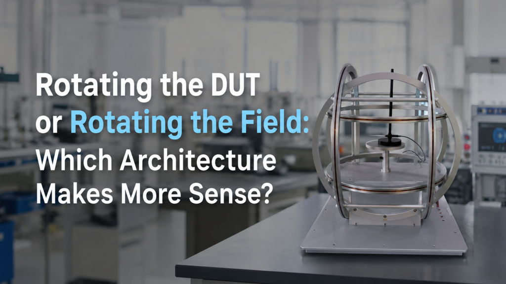
- Two-axis Helmholtz coil system
- Three-axis Helmholtz coil system
- Multi-axis magnetic field driver
- Software-controlled vector field generation
- Synchronized current control across axes
In this architecture, the system changes the magnetic field direction by adjusting current in different coil axes.
A Helmholtz coil is commonly used to generate a region of nearly uniform magnetic field near the center, and three-axis arrangements can be used to control magnetic fields in different directions.
Reference link: https://en.wikipedia.org/wiki/Helmholtz_coil
3. Why This Choice Matters
At first, the difference may look simple:
- Rotating DUT = mechanical rotation
- Rotating field = electronic vector control
But in real test systems, the choice affects:
- Calibration accuracy
- Angular error
- Field uniformity
- Fixture complexity
- Cable movement
- Software complexity
- Test speed
- Repeatability
- Cost
- Maintenance
- User training
- Acceptance criteria
The wrong architecture may still “work,” but it can create unnecessary error sources and make the experiment harder to control.
4. Architecture A: Rotating the DUT
Rotating the DUT is often the most direct approach.
The magnetic field can remain fixed while the sensor, sample, or device is physically rotated through different angles.
Common Use Cases
Rotating the DUT is often used for:
- Magnetometer calibration
- Compass heading validation
- IMU orientation testing
- Angular response measurement
- Material anisotropy testing
- Hall sensor angle response
- MOKE angular studies
- Direction-dependent magnetic measurements
Main Advantages
The advantages are clear:
- Easy to understand
- Matches real orientation changes
- Can use a simpler one-axis or two-axis field source
- Useful for angular response measurement
- Suitable when the DUT must be tested in real physical positions
- Can be combined with existing rotary stages
For many basic tests, rotating the DUT is practical and cost-effective.
5. Main Risks When Rotating the DUT
The problem is that mechanical rotation introduces mechanical error.
Common Error Sources
Rotating the DUT can introduce:
- Turntable angular error
- Backlash
- Rotation axis runout
- Sensor not centered
- Fixture tilt
- Cable drag
- Position shift during rotation
- Non-magnetic fixture limitations
- Magnetic contamination from stage components
- Poor repeatability after remounting
For magnetometer, compass, and IMU calibration, these errors can become serious.
A high-quality magnetic field does not help much if the sensor orientation is not actually what the software assumes.
6. Cable Movement Is a Real Problem
When the DUT rotates, cables often rotate too.
This can create several problems:
- Cable pulling changes sensor position
- Cable loops generate magnetic disturbance
- Cable stiffness creates torque on the fixture
- Repeated movement reduces repeatability
- Signal noise may change with angle
- Connectors may interfere with the rotation range
In low-field calibration, cable routing is not a small detail.
If the field target is close to Earth-field level, cable movement and nearby current loops may quietly affect measurement results.
This is one reason many calibration systems try to keep the DUT fixed when possible.
7. Architecture B: Rotating the Field
Rotating the field keeps the DUT stationary and changes the magnetic vector electronically.
A three-axis coil system can generate different vector directions by controlling current in each coil axis.
For example, the system may generate:
- +X field
- -X field
- +Y field
- -Y field
- +Z field
- -Z field
- Rotating vector in the XY plane
- Tilted vector field
- Simulated Earth-field direction
- Custom angular scan sequence
This architecture is especially useful when the DUT is fragile, cable-heavy, difficult to move, or must remain fixed relative to other equipment.
8. Main Advantages of Rotating the Field
Rotating the field can reduce mechanical problems.
Key Advantages
It can help with:
- Fixed sensor position
- Reduced cable movement
- Better automation
- Faster test sequences
- Programmable field angles
- Repeatable vector generation
- Reduced mechanical wear
- Easier integration with stationary fixtures
- Better suitability for production testing
For automated calibration, rotating the field is often attractive because software can generate repeatable test sequences without moving the DUT.
NIST’s magnetic sensing and metrology work covers magnetic sensors used across many demanding applications, including industrial, electronics, environmental, infrastructure, and defense fields. This broad application range is one reason controlled magnetic field generation and repeatable calibration setups matter.
Reference link: https://www.nist.gov/programs-projects/magnetic-sensing-and-metrology
9. Main Risks When Rotating the Field
Rotating the field is not automatically easier.
It shifts the complexity from mechanics to magnetic control and software.
Common Error Sources
Rotating the field may introduce:
- Coil-axis misalignment
- Three-axis non-orthogonality
- Driver channel mismatch
- Current resolution limits
- Current stability differences between axes
- Field vector calculation errors
- Background field compensation errors
- Cross-axis coupling
- Calibration matrix errors
- Software sequence mistakes
The DUT may not move, but the magnetic vector must be calculated and generated correctly.
If the coil axes are not well characterized, the commanded field vector may not match the real field vector.
10. Field Rotation Requires Good Vector Control
Rotating a field is not just “turning on three coils.”
The control system must know how each coil axis contributes to the field at the DUT position.
Important factors include:
- Coil constant for each axis
- Axis orthogonality
- Field-current linearity
- Driver calibration
- Background field offset
- Coordinate system definition
- Field probe verification
- Software transformation between lab coordinates and DUT coordinates
For precision work, the system may need a calibration matrix so that commanded field vectors match measured field vectors.
Without this, rotating the field may look elegant in software but produce inaccurate physical results.
11. Uniformity Matters in Both Architectures
Whether the DUT rotates or the field rotates, field uniformity still matters.
If the DUT Rotates
The sensor may move away from the exact coil center.
This can happen because of:
- Fixture offset
- Rotation radius
- Cable force
- Stage runout
- Poor centering
If the sensor moves through a non-uniform field, the measurement may change because of position, not angle.
If the Field Rotates
The DUT may remain fixed, but the field contribution from each coil axis must be uniform at the DUT location.
For three-axis systems, each axis should provide suitable field quality over the required test volume.
A three-axis coil system is only as good as its weakest axis.
12. Angular Accuracy vs. Vector Accuracy
The two architectures focus on different types of accuracy.
Rotating the DUT Depends on Angular Accuracy
Important specifications include:
- Turntable angular accuracy
- Repeatability
- Resolution
- Backlash
- Rotation center
- Fixture alignment
- Sensor mounting error
Rotating the Field Depends on Vector Accuracy
Important specifications include:
- Field magnitude accuracy
- Field direction accuracy
- Axis orthogonality
- Current control accuracy
- Driver stability
- Background compensation
- Coordinate transformation
The buyer should decide which type of accuracy is easier to control in the real experiment.
13. When Rotating the DUT Makes More Sense
Rotating the DUT is usually a good choice when:
- The DUT is small and easy to mount
- Cable movement is manageable
- The required angle range is simple
- A turntable is already available
- The field source is one-axis or two-axis
- Real physical orientation must be tested
- The budget is limited
- The software requirement should stay simple
Typical Examples
Rotating the DUT may be suitable for:
- Basic compass testing
- Sensor angular response measurement
- Single-axis field exposure
- Material anisotropy scans
- Research setups with manual angle adjustment
- Educational lab experiments
If the team has good mechanical fixtures and does not need high automation, this architecture can be practical.
14. When Rotating the Field Makes More Sense
Rotating the field is usually a better choice when:
- The DUT should remain fixed
- Cable movement must be avoided
- The test requires many angle points
- Automation is important
- The DUT is fragile or integrated into a larger setup
- Three-axis magnetic vector control is required
- Production calibration needs repeatability
- Mechanical rotation would introduce too much error
Typical Examples
Rotating the field may be suitable for:
- Magnetometer calibration
- IMU magnetic response testing
- Geomagnetic simulation
- Automated compass calibration
- Fixed sensor module testing
- Cable-heavy DUT testing
- Three-axis vector field experiments
For high-throughput or repeatable calibration workflows, rotating the field can save time and reduce mechanical variability.
15. When a Hybrid Architecture Is Best
Sometimes the best answer is not one or the other.
A hybrid system may use both:
- Three-axis field rotation
- Mechanical turntable
- Fixed field with rotating DUT
- Fixed DUT with programmable vector field
- Occasional mechanical repositioning plus electronic fine control
Why Use a Hybrid System?
A hybrid architecture may help when:
- Full 3D orientation is required
- The DUT coordinate system must be validated physically
- Field vector control cannot cover every test condition
- The sample must be rotated relative to an optical path
- Material anisotropy requires real sample rotation
- Calibration and verification use different methods
For example, a sensor may be calibrated using electronic field rotation, then verified with selected physical rotations.
This can reduce test time while still checking real orientation behavior.
16. Material Testing: Physical Rotation Often Still Matters
For magnetic materials, rotating the field and rotating the sample are not always equivalent.
A material may have direction-dependent properties related to:
- Crystal orientation
- Film plane
- easy axis
- hard axis
- sample geometry
- optical path
- current direction
- strain direction
- anisotropic behavior
In these cases, physically rotating the sample may be necessary because the sample’s orientation relative to the measurement system matters.
For example, in magneto-optical or electrical measurements, the relationship between magnetic field direction, sample plane, current path, and optical access may define the experiment.
A rotating field may simplify some scans, but it may not replace physical sample rotation in every material test.
17. Sensor Calibration: Rotating Field Often Reduces Workflow Risk
For magnetometer, compass, and IMU calibration, rotating the field is often attractive because the sensor can remain fixed.
Three-axis magnetic field sensor calibration is an active topic in measurement and navigation research, and a 2021 review discusses calibration algorithms for three-axis magnetic field sensors and compares approaches using real and artificial sensor data.
Reference link: https://pmc.ncbi.nlm.nih.gov/articles/PMC8401862/
For laboratory calibration systems, this means architecture matters.
A fixed DUT plus programmable field can reduce:
- Cable movement
- remounting error
- operator variation
- mechanical backlash
- test time
- fixture complexity
But it increases the need for:
- three-axis coil calibration
- field verification
- software control
- coordinate transformation
- background field compensation
The choice depends on whether mechanical error or field-vector error is easier to manage.
18. Questions to Ask Before Choosing an Architecture
Before selecting a system, buyers should answer these questions.
About the DUT
- Is the DUT small or large?
- Is it fragile?
- Does it have many cables?
- Can it rotate freely?
- Does cable movement affect measurement?
- Does the DUT need to stay aligned with optics, probes, or fixtures?
About the Magnetic Field
- What field range is required?
- Is one-axis, two-axis, or three-axis field control needed?
- Is the field DC, AC, sweep, or rotating vector?
- What field uniformity is required?
- Is background field compensation needed?
- Is field direction accuracy important?
About the Motion System
- What angular accuracy is required?
- Is manual rotation acceptable?
- Is motorized rotation required?
- Is backlash acceptable?
- Does the rotation axis pass through the DUT center?
- Are the stage materials non-magnetic?
About Automation
- How many angle points are needed?
- How many devices will be tested?
- Is production throughput important?
- Is software sequencing required?
- Is data logging required?
- Is repeatability more important than manual flexibility?
These questions usually reveal which architecture is more practical.
19. Practical Comparison
Rotating the DUT
Best when:
- Physical orientation must be tested
- The DUT is easy to mount
- Angle control is the main requirement
- Mechanical rotation is reliable
- The field source can be simple
Main risks:
- Turntable error
- fixture misalignment
- cable movement
- magnetic parts in stages
- poor repeatability
Rotating the Field
Best when:
- The DUT should remain fixed
- Three-axis vector control is needed
- Automation is important
- Cable movement must be avoided
- Test sequences require many field directions
Main risks:
- Coil-axis error
- driver mismatch
- vector calculation error
- background field compensation
- software complexity
Hybrid System
Best when:
- Both physical orientation and magnetic vector control matter
- Material anisotropy must be studied
- Sensor calibration needs independent verification
- Complex angular scans are required
- The experiment has multiple test modes
Main risks:
- Higher cost
- more complex control
- more acceptance criteria
- harder troubleshooting
20. How Cryomagtech Supports Rotating Field and DUT Rotation Architectures
Cryomagtech supplies Helmholtz coil systems, three-axis magnetic field systems, magnetic field drivers, calibration fixtures, and custom magnetic test platforms for sensor calibration, geomagnetic simulation, and angular magnetic testing.
For projects involving DUT rotation or rotating field control, we help evaluate:
- One-axis, two-axis, or three-axis coil configuration
- Field range and uniformity
- DUT size and fixture design
- Turntable or fixed-holder requirements
- Non-magnetic material selection
- Cable routing strategy
- Driver resolution and stability
- Software-controlled vector field generation
- Field verification and acceptance criteria
- Hybrid architecture options
👉 Product link placeholder: Cryomagtech Three-Axis Magnetic Field and Calibration Platform Solutions
A good architecture is not the one that sounds more advanced.
It is the one that controls the dominant error source in your real experiment.
References
- NIST – Magnetic Sensing and Metrology
https://www.nist.gov/programs-projects/magnetic-sensing-and-metrology - Wikipedia – Helmholtz Coil
https://en.wikipedia.org/wiki/Helmholtz_coil - Sensors – Magnetic Field Sensors’ Calibration: Algorithms’ Overview
https://pmc.ncbi.nlm.nih.gov/articles/PMC8401862/
Key Takeaways
- Rotating the DUT and rotating the magnetic field are both valid architectures.
- Rotating the DUT is mechanically intuitive but can introduce angular error, cable movement, and fixture repeatability issues.
- Rotating the field reduces mechanical movement but requires accurate three-axis coil control, driver stability, and field-vector calibration.
- Sensor calibration often benefits from fixed DUT and programmable field rotation.
- Material testing may still require physical sample rotation when sample orientation matters.
- Hybrid architectures can be powerful but need clear scope and acceptance criteria.
- The best architecture depends on which error source is easier to control: mechanical angle or magnetic vector.
For angular magnetic testing, the real question is not only:
“Can the system rotate?”
The better question is:
“Should we rotate the DUT, rotate the field, or combine both to control the dominant error source?”