Laboratory magnet systems are powerful electrical and thermal devices.
A modern electromagnet or high-current Helmholtz system may involve:
- High DC current
- Significant heat dissipation
- Water cooling loops
- Iron cores with stored magnetic energy
Without proper safety and interlock design, a minor fault can escalate into equipment damage or safety risk.
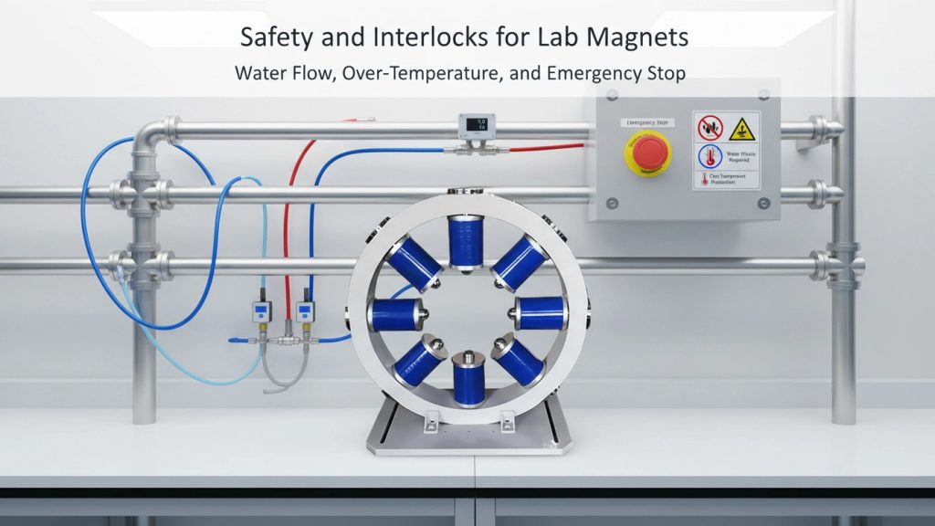
This article explains essential safety mechanisms for lab magnets — including water flow monitoring, over-temperature protection, grounding strategy, and emergency stop integration.
1. Why Interlocks Matter in Laboratory Magnet Systems
Magnet systems combine:
- Electrical energy
- Thermal energy
- Mechanical force
When any control fails, damage can occur rapidly.
Electrical safety fundamentals are described in Wikipedia under Electrical safety:
https://en.wikipedia.org/wiki/Electrical_safety
In high-current magnet systems, protection must act faster than human response.
Interlocks provide automatic fault interruption before damage escalates.
2. Water Flow Monitoring: Preventing Coil Overheating
Water-cooled electromagnets rely on continuous coolant flow.
If flow stops:
- Copper temperature rises quickly
- Insulation degrades
- Coil deformation may occur
Typical Protection Methods
- Flow switches (mechanical or electronic)
- Flow sensors with analog output
- Minimum flow threshold detection
Interlock logic:
If flow < setpoint → disable power stage immediately.
Advanced systems include:
- Redundant flow detection
- Time-delay shutdown logic
- Cooling system startup verification
Flow monitoring is mandatory for high-field, high-current magnets.
3. Over-Temperature Protection
Even with proper water flow, thermal issues can arise.
Causes include:
- Chiller failure
- Blocked cooling channel
- Ambient temperature rise
- High duty cycle stress
Protection Elements
- Embedded PT100/PT1000 sensors
- Thermocouples inside coil structure
- Heatsink temperature monitoring
- Core temperature sensors
Over-temperature interlock design typically includes:
- Warning threshold
- Critical shutdown threshold
- Automatic reset conditions
Thermal protection must be independent of software control to ensure hardware-level safety.
4. Leak Detection in Water-Cooled Systems
Water leakage near high-current conductors is hazardous.
Protection strategies include:
- Drip trays with sensor switches
- Conductivity-based leak detection strips
- Pressure decay monitoring
When leak detected:
- Power output disabled
- Audible alarm triggered
- Operator notification logged
Safety logic should default to fail-safe condition.
5. Grounding and Electrical Protection
Improper grounding can cause:
- Shock risk
- Ground loops
- EMI interference
- Unstable measurement signals
Grounding principles are discussed extensively in electromagnetic compatibility (EMC) literature from IEEE:
https://ieeexplore.ieee.org/
Best practices include:
- Protective earth bonding
- Single-point grounding
- Shield termination strategy
- Isolated signal returns
Proper grounding protects both people and data.
6. Emergency Stop (E-Stop) Integration
An emergency stop button is not decorative.
It must:
- Physically interrupt the power stage
- Override software control
- Be clearly accessible
- Comply with local safety standards
Effective E-stop design includes:
- Latching mechanical switch
- Hardwired power cutoff
- Clear status indicator
- Reset verification procedure
For integrated systems:
- Magnet
- Power supply
- Cooling system
All subsystems must respond to E-stop simultaneously.
7. Interlock Architecture: Hardware vs Software
Safety interlocks must prioritize hardware-based logic.
Software-based control is insufficient alone.
Recommended architecture:
Layer 1: Hardware interlock chain
Layer 2: Firmware monitoring
Layer 3: User interface alert
If firmware fails, hardware must still cut power.
8. Documentation and Compliance Considerations
Research procurement increasingly requires:
- Risk assessment documentation
- Electrical schematics
- Interlock diagrams
- CE / local compliance statements
A professional magnet system includes:
- Interlock logic description
- Sensor specification
- Shutdown timing response
- Safety validation testing
Safety documentation strengthens grant compliance and audit readiness.
👉 Product Link Placeholder – Cryomagtech Electromagnet & Helmholtz Integrated Systems
Our magnet systems integrate:
- Flow monitoring
- Thermal sensors
- Hardware interlocks
- Emergency stop architecture
- Grounding design best practices
Safety is engineered into the system — not added later.
9. Why Safety Design Reflects Engineering Maturity
Any supplier can quote field strength.
Fewer provide:
- Integrated protection systems
- Redundant safety logic
- Complete documentation
Interlocks are not optional features.
They indicate system-level engineering discipline.
Key Takeaways
- Water flow monitoring prevents coil overheating
- Over-temperature protection must act independently of software
- Leak detection is critical in water-cooled systems
- Proper grounding protects both users and data
- Emergency stop must physically interrupt power
- Hardware interlocks are mandatory for safe operation
A laboratory magnet system must be designed as a controlled energy system — not just a magnetic field source.
References
- Wikipedia – Electrical Safety
https://en.wikipedia.org/wiki/Electrical_safety - IEEE – Electromagnetic compatibility and grounding practices
https://ieeexplore.ieee.org/