
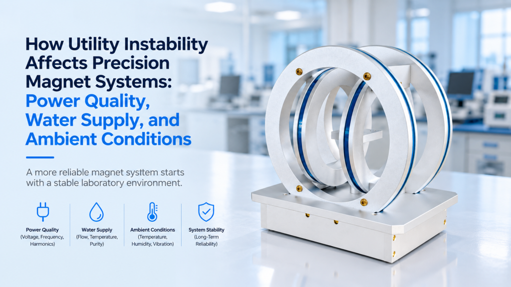
When a precision magnet system does not perform as expected, the first suspicion usually falls on the equipment itself.
The magnet may appear unstable.
The Hall voltage may become noisy.
A VSM baseline may drift.
A cryogenic system may take longer to cool down.
An electromagnet may trip during high-field operation.
But the instrument is not always the root cause.
A precision magnet system operates inside a larger laboratory infrastructure that includes:
- AC power
- Protective grounding
- Cooling water
- Chiller performance
- Room temperature
- Humidity
- Ventilation
- Vibration
- Ambient magnetic fields
- Electromagnetic interference
If those conditions are unstable, even a well-designed instrument may produce unstable performance.
This is especially important for overseas installations, shared university facilities, laboratories with aging infrastructure, and systems expected to operate continuously for many hours or days.
The correct procurement question is therefore not only:
“What are the specifications of the magnet system?”
It is also:
“Can the laboratory utilities support those specifications continuously?”
This article explains how power quality, cooling water, and ambient laboratory conditions can affect precision magnet systems—and what buyers should define before installation.
1. Instrument Specifications Assume an Operating Environment
A specification such as:
- Field stability: 25 ppm/h
- Temperature stability: ±0.1 K
- Magnetic-field range: ±1 T
- Continuous operation: 100%
- VSM sensitivity: 10⁻⁵ emu
does not exist independently of the laboratory.
These values are normally achieved under defined operating conditions.
The complete performance chain may involve:
Utility supply → Power electronics → Magnet → Sensor → Sample environment → Measurement electronics → Data
Instability anywhere upstream can appear later as measurement instability.
This means laboratory infrastructure should be considered part of the measurement system.
2. Three Utility Groups Matter Most
For many magnetic measurement systems, the most important site conditions can be divided into three groups.
Electrical
- Voltage
- Frequency
- Phase
- Current capacity
- Power quality
- Grounding
Cooling
- Water temperature
- Flow rate
- Pressure
- Water quality
- Chiller capacity
Ambient Environment
- Room temperature
- Humidity
- Ventilation
- Vibration
- Magnetic background
- Electromagnetic interference
A problem in one group can sometimes look like a failure in another.
That is why troubleshooting should begin with system-level thinking.
3. Power Quality Is More Than “230 V Is Available”
A laboratory may state:
“We have 230 VAC.”
That tells only part of the story.
A nominal voltage does not describe what happens over minutes, hours, or during heavy loading elsewhere in the building.
IEEE 1159 provides a framework for monitoring electric power quality and distinguishes nominal electrical conditions from deviations originating in the supply, loads, or interactions between them. It also addresses methods for monitoring and interpreting these conditions.
For a precision magnet system, relevant power problems can include:
- Voltage sag
- Temporary overvoltage
- Short interruption
- Switching transient
- Electrical noise
- Harmonic distortion
- Frequency instability
- Three-phase imbalance
Not every system is equally sensitive to all of these conditions.
But they should not be ignored simply because the outlet measures the correct nominal voltage with a handheld meter.
4. Voltage Sags Can Cause Intermittent Problems
A voltage sag may last too briefly for laboratory staff to notice.
But sensitive equipment may notice it immediately.
Possible symptoms include:
- Power-supply reset
- Communication loss
- Interlock trip
- Computer reboot
- Chiller shutdown
- Cryocooler compressor alarm
- Interrupted measurement sequence
This can be particularly frustrating because the system may operate normally again seconds later.
The user then sees only:
“Measurement aborted.”
without knowing that the original event occurred in the building power supply.
5. High-Power Magnets Can Expose Weak Electrical Infrastructure
Large electromagnets can require substantial electrical power.
At high magnetic field, the system may draw much more power than during standby or low-field testing.
A site may appear suitable when:
- Computer is running
- Electronics are powered
- Magnet current is low
but behave differently when the magnet reaches maximum current.
Problems can include:
- Breaker trips
- Excessive voltage drop
- Connector heating
- Power-supply undervoltage alarms
- Reduced continuous-duty capability
Therefore, electrical capacity should be checked for the maximum intended operating condition, not only idle operation.
6. Dedicated Circuits Can Reduce Unexpected Interactions
A precision magnet system may share building power with:
- Vacuum pumps
- HVAC equipment
- Furnaces
- Laser systems
- Compressors
- Elevators
- Machine tools
When these loads start or stop, they may disturb the local electrical environment.
Where practical and required by the equipment design, high-power subsystems may benefit from appropriately rated dedicated circuits.
This is particularly relevant for:
- Magnet power supplies
- Water chillers
- Cryocooler compressors
- Large vacuum pumps
The final electrical design should always follow the manufacturer specifications and local electrical code.
7. Three-Phase Power Must Be Defined Precisely
Some high-power compressors, chillers, and magnet supplies require three-phase power.
“Three-phase available” is still incomplete.
The supplier may need to know:
- Line-to-line voltage
- Frequency
- Maximum current
- Phase configuration
- Breaker capacity
- Connector standard
International projects frequently encounter differences such as:
- 200 V
- 208 V
- 220 V
- 380 V
- 400 V
- 415 V
- 440 V
- 480 V
A system configured for one supply should not be assumed compatible with every three-phase network.
8. Frequency Matters for Some Equipment
Most modern electronics tolerate the frequency range stated on their nameplate.
But motors, compressors, pumps, and some transformers may be more configuration-dependent.
A system intended for:
- 50 Hz
should not automatically be assumed equivalent at:
- 60 Hz
unless the relevant components are rated accordingly.
This is particularly important for overseas projects where the magnet system, chiller, compressor, and auxiliary equipment may come from different suppliers.
9. Grounding Problems Can Look Like Measurement Noise
A system may have excellent electrical specifications and still produce noisy data if grounding is poorly implemented.
Possible symptoms include:
- 50 Hz or 60 Hz pickup
- Hall-voltage noise
- Temperature-sensor instability
- MOKE detector noise
- Unexplained voltage offsets
- Communication problems
This is especially important for measurements involving:
- Microvolt signals
- Lock-in amplifiers
- Hall measurements
- Cryogenic transport
- Low-noise electrometers
The key objective is not simply to connect every chassis to as many ground points as possible.
The grounding topology should be deliberate.
Protective earth must remain intact for safety; attempts to solve measurement noise should never involve defeating required protective grounding.
10. Signal Ground and Protective Earth Are Different Problems
Users sometimes treat “ground” as one single concept.
In an integrated system, there may be:
- Protective earth
- Chassis ground
- Signal reference
- Cable shield
- Cryostat ground
- Computer ground
- Instrument analog ground
Poorly planned connections can create unintended current paths.
For complex Hall, cryogenic, and optical magnetic measurements, the grounding plan should therefore be documented rather than assembled experimentally after noise appears.
11. Electrical Noise Can Enter Through More Than the AC Line
Even when AC power itself is acceptable, interference can enter through:
- USB cables
- Ethernet
- RS-232
- Sensor wiring
- Analog inputs
- Long shield connections
- External trigger lines
This is why noise troubleshooting should not stop at installing a power filter.
The complete signal architecture matters.
12. A UPS Is Not Automatically the Solution
When users worry about unstable power, they often ask:
“Should we put the entire system on a UPS?”
Sometimes that is useful.
Sometimes it is impractical.
Large magnet power supplies, chillers, pumps, or cryocooler compressors can require substantial power. An ordinary office UPS may not support:
- Required continuous power
- Startup current
- Three-phase operation
- Regenerative loads
- Long backup duration
A more practical strategy may be to protect only selected subsystems such as:
- Control computer
- PLC
- Measurement electronics
- Data-acquisition system
while handling the high-power equipment through a controlled shutdown strategy.
UPS compatibility should be evaluated with the actual power-supply manufacturer rather than assumed.
13. Power-Outage Behavior Should Be Defined Before Installation
For a long automated experiment, ask:
What happens if power disappears for five seconds?
And:
What happens if it disappears for one hour?
The answer may differ between systems.
Possible responses include:
- Magnet field collapses
- Measurement sequence stops
- Data file closes incorrectly
- Chiller stops
- Vacuum pump stops
- Temperature begins to rise
- Cryogenic subsystem enters a protection state
For complex low-temperature or superconducting systems, shutdown and restart procedures should follow the specific manufacturer’s instructions.
The important point is that power failure should be treated as a defined operating scenario.
14. Power Recovery Can Be as Important as Power Loss
Equipment may not always restart safely when power returns.
Imagine this sequence:
- Power fails
- Cooling stops
- Power returns
- Magnet power supply restarts
- Cooling has not yet recovered
A good system architecture uses:
- Interlocks
- Controlled startup
- Fault-state logic
- Flow verification
- Temperature protection
so that high-power operation cannot resume before required supporting systems are available.
15. Cooling Water Is Part of the Magnet Specification
For a water-cooled electromagnet, the magnet is only one part of the thermal system.
The actual thermal chain is:
Coil → Cooling channel → Coolant → Hose → Chiller or facility water → Room / building heat rejection
If any part is inadequate, coil temperature rises.
This can affect:
- Continuous operation
- Coil resistance
- Power-supply voltage demand
- Thermal drift
- Component lifetime
Therefore, “water cooling included” is not a complete specification.
16. Flow Rate Must Be Maintained During Real Operation
The system may require a minimum coolant flow.
Low flow can result from:
- Undersized pump
- Long hoses
- Small hose diameter
- Dirty filter
- Partially closed valve
- Kinked tubing
- Scale buildup
- Shared facility-water demand
A flow value measured once during installation does not guarantee the same flow six months later.
For heavily used systems, flow monitoring can be valuable.
17. Water Temperature Changes Cooling Capacity
Cooling water at 15 °C and cooling water at 30 °C do not provide the same thermal margin.
Warmer cooling water means a smaller temperature difference between the coolant and the heat-producing component.
The magnet may then operate at a higher coil temperature.
In a current-regulated electromagnet, the power supply will normally attempt to maintain the commanded current as coil resistance changes.
But increasing resistance also increases the required supply voltage.
If the system approaches its voltage or thermal limit, regulation or continuous-duty capability may eventually be affected.
This is why magnet specifications should be evaluated together with the expected cooling-water temperature.
18. Colder Water Is Not Always Better
It is tempting to think:
“If 20 °C water is good, 5 °C must be better.”
Not necessarily.
If cooling surfaces or hoses fall below the laboratory dew point, condensation may form.
That can create risks around:
- Electrical connectors
- Coil insulation
- Metal surfaces
- Electronics
- Optical components
The correct coolant temperature should stay within the manufacturer’s specified operating range and avoid condensation.
19. Cooling Requirements Can Change with Water Temperature
Some cryogenic systems explicitly specify different minimum water-flow requirements depending on cooling-water temperature.
This illustrates an important engineering principle:
cooling-water temperature and cooling-water flow should not be treated as independent specifications.
The thermal capacity of the complete cooling loop matters.
20. High-End Magnetic Systems Explicitly Specify Site Utilities
This is not theoretical.
Quantum Design’s installation requirements for an MPMS SQUID VSM EverCool system specify laboratory ambient temperature and humidity, open airflow for cooling, vibration requirements, AC power, and water cooling for the cryocooler compressor. The document also specifies system power requirements and installation conditions rather than treating the instrument as independent of the laboratory environment.
The lesson extends beyond one manufacturer’s system:
precision measurement equipment normally assumes defined site conditions.
A laboratory that cannot maintain them should address the infrastructure before blaming the instrument.
21. Facility Water and Dedicated Chillers Behave Differently
Two common cooling approaches are:
Facility Cooling Water
Potential advantages:
- No separate chiller
- High available cooling capacity
- Less local heat rejection
Potential concerns:
- Variable temperature
- Variable pressure
- Shared demand
- Water quality
- Building shutdowns
Dedicated Chiller
Potential advantages:
- More controlled temperature
- Known local flow
- Independent operation
Potential concerns:
- Additional heat released into the room
- Maintenance
- Noise
- Pump vibration
- Electrical power requirement
The correct choice depends on laboratory infrastructure and system power.
22. Water Quality Can Become a Long-Term Reliability Issue
Cooling circuits can gradually develop problems from:
- Scale
- Corrosion
- Particulates
- Biological growth
- Incorrect coolant chemistry
These may reduce flow or heat transfer long before complete blockage occurs.
For long-life water-cooled systems, users should follow the specified coolant-quality and maintenance requirements rather than simply filling the system with whatever water is available.
23. Chiller Placement Can Affect Measurement Quality
A chiller contains:
- Pump
- Fan
- Compressor
- Motor
These components can generate:
- Acoustic noise
- Mechanical vibration
- Heat
Placing the chiller directly against a sensitive VSM, optical table, or low-noise measurement system may create unnecessary problems.
Where system design permits, separating noisy utility equipment from the measurement area can improve the laboratory environment.
24. Room Temperature Affects More Than User Comfort
Ambient temperature can influence:
- Electronics drift
- Sensor response
- Coil resistance
- Mechanical dimensions
- Optical alignment
- Cryostat heat load
- Chiller efficiency
A magnet system may still operate throughout a wide allowable room-temperature range.
But operating range and best precision conditions are not always the same thing.
For precision measurements, stability can matter more than the absolute room temperature.
A laboratory cycling repeatedly between warm daytime and cool nighttime conditions may create more drift than one operating steadily at a slightly different temperature.
25. Air-Conditioning Cycles Can Appear in Long Measurements
Imagine a six-hour measurement.
The laboratory HVAC repeatedly switches:
- ON
- OFF
- ON
- OFF
Room temperature slowly oscillates.
Depending on the experiment, this can correlate with:
- Electronics baseline
- Optical alignment
- Temperature-control load
- Mechanical drift
If an unexplained signal shows periodic drift, it can be useful to compare the data with room-temperature logs.
Not every periodic feature originates in the sample.
26. Humidity Matters Mainly at the Extremes
High humidity can contribute to:
- Condensation risk
- Corrosion
- Surface leakage in sensitive electronics
Very low humidity can increase electrostatic-discharge risk.
For most magnet systems, the correct target is not an arbitrary universal humidity value.
It is:
the non-condensing operating range specified for the complete equipment package.
This becomes especially important when chilled surfaces are present.
27. Ventilation Is Easy to Forget
Power electronics, chillers, pumps, and magnet coils ultimately produce heat.
If that heat is released into a small laboratory, room temperature can rise significantly during long operation.
Common installation mistakes include:
- Power supply inside a closed cabinet
- Chiller under a bench with blocked exhaust
- Magnet cooling fan against a wall
- Multiple high-power systems in a small room
The room HVAC must remove the heat that the equipment ultimately rejects.
Otherwise, the laboratory can enter a thermal feedback cycle:
equipment heats room → cooling becomes less effective → equipment runs hotter
28. Vibration Can Be a Utility Problem Too
Not all environmental problems are electrical or thermal.
Vibration can come from:
- Building HVAC
- Water pumps
- Chillers
- Vacuum pumps
- Cryocoolers
- Elevators
- Nearby machinery
This is especially relevant for:
- VSM
- MOKE
- Optical experiments
- Probe positioning
- High-resolution cryogenic measurements
A magnet may produce perfectly stable field while mechanical vibration degrades the measured signal.
29. Do Not Put Every Pump on the Same Table
Vacuum pumps and chillers are often installed wherever space is available.
That may be convenient but not optimal.
Where mechanical sensitivity matters, consider:
- Separate floor mounting
- Flexible hoses
- Vibration-isolation elements
- Remote pump placement
- Independent equipment racks
The best configuration depends on the measurement sensitivity and equipment design.
30. Ambient Magnetic Conditions Can Change the Experiment
The laboratory environment also contains magnetic disturbances.
Possible sources include:
- Elevators
- Transformers
- Building power cables
- Motors
- Steel furniture
- Nearby electromagnets
- Moving vehicles
For a 1 T electromagnet operating near saturation, many of these disturbances are insignificant relative to the applied field.
For a Helmholtz system generating:
- 10 µT
- 50 µT
- 100 µT
they may become part of the experiment.
This distinction is critical for:
- Magnetic sensor calibration
- Earth’s-field simulation
- Active compensation
- Biomagnetic experiments
- Low-field MOKE
- Precision vector-field generation
31. Utility Problems Often Appear as Drift Rather Than Failure
This is what makes infrastructure problems difficult to diagnose.
A catastrophic failure is obvious.
Utility instability often creates subtler symptoms:
- Slightly different field each morning
- Hall mobility changing between runs
- Baseline slowly drifting
- More noise during afternoon hours
- Longer cryogenic stabilization
- Repeated interlock trips only at high field
These problems can be wrongly attributed to:
- Magnet calibration
- Sample variability
- Software
- Sensor failure
before anyone checks the laboratory utilities.
32. A One-Time Site Check Is Not Enough for Long Experiments
Suppose an engineer measures:
- 230 V AC
- 20 °C cooling water
- 22 °C room temperature
during installation.
Everything looks correct.
But the real experiment runs overnight for 12 hours.
The relevant question becomes:
Were those conditions stable during the entire measurement?
For critical systems, useful monitoring may include:
- AC voltage
- Cooling-water temperature
- Water flow
- Room temperature
- Room humidity
These logs can be compared with measurement data when troubleshooting drift.
33. Site Preparation Should Begin Before the Equipment Ships
For international installations, the supplier should ideally collect utility information before manufacturing or shipment.
A useful site-preparation form may include:
Electrical
- Country
- Nominal voltage
- Frequency
- Single or three phase
- Available current
- Breaker capacity
- Outlet type
Cooling
- Facility water or chiller
- Inlet temperature range
- Flow capability
- Pressure
- Hose connection
Environment
- Minimum room temperature
- Maximum room temperature
- Humidity range
- Air-conditioning
- Vibration sources
Installation
- Available floor space
- Ventilation
- Distance between chiller and magnet
- Nearby high-power equipment
This prevents avoidable surprises during commissioning.
34. Maximum and Minimum Utility Conditions Matter More Than Nominal Values
A customer may state:
“Cooling water is normally 20 °C.”
The more useful questions are:
- What is the warmest it becomes?
- What is the coldest?
- Does flow fall when other laboratories use the same line?
Similarly:
“Power is 230 V.”
should become:
- What variation occurs?
- Are outages common?
- Are large motors connected nearby?
- Is the system on a dedicated circuit?
Precision-system design should consider the worst credible operating condition, not only the nominal condition.
35. Different Subsystems May Need Different Utility Strategies
An integrated system may include:
- Electromagnet
- Power supply
- Hall measurement electronics
- Cryostat
- Vacuum pump
- Chiller
- Computer
They do not all have the same sensitivity.
For example:
High-Power Equipment
May prioritize:
- Electrical capacity
- Cooling
- Interlocks
Measurement Electronics
May prioritize:
- Low electrical noise
- Grounding
- Power continuity
Cryogenic Equipment
May prioritize:
- Cooling-water reliability
- Compressor power
- Vacuum
- Ambient heat load
The best site design treats these requirements separately before reconnecting them as one system.
36. Hall Systems Are Especially Sensitive to Electrical Noise
Hall measurements can involve small transverse voltages.
Poor grounding, unstable current, electrical pickup, and temperature drift can all affect measured results.
If carrier concentration or mobility suddenly becomes inconsistent after installation, check not only:
- Sample contacts
- Magnet
- Software
but also:
- Current-source stability
- grounding
- AC interference
- ambient temperature
The measurement chain matters more than the nameplate specification of any single instrument.
37. VSM Systems Need Stable Mechanical and Thermal Conditions
A VSM measures magnetic moment through sample vibration.
Possible utility-related influences include:
- Floor vibration
- Chiller vibration
- Room-temperature changes
- Power interruption
- Cooling-system instability
The system may remain operational while its background noise changes.
Reference-sample measurements are therefore useful when evaluating a new laboratory environment.
38. Cryogenic Systems Are Particularly Infrastructure-Dependent
Low-temperature equipment can depend simultaneously on:
- Electrical power
- Compressor operation
- Cooling water
- Vacuum
- Room temperature
- Ventilation
One unstable utility can affect another subsystem.
For example:
Warm cooling water → compressor performance changes → cryogenic load changes → cooldown or temperature behavior changes
This is why cryogenic systems should be evaluated as complete installations rather than isolated instruments.
39. Helmholtz Coil Systems Need Stable Current and Stable Environment
For Helmholtz coils, field is strongly related to coil current and geometry.
A high-quality current source can provide excellent stability.
But system performance can still be affected by:
- Coil heating
- Current-source thermal drift
- Ambient magnetic-field changes
- Nearby ferromagnetic movement
- Room-temperature changes
For long-duration low-field applications, ambient conditions may become comparable to the field accuracy being requested.
40. Troubleshoot Infrastructure Before Changing Calibration
When a precision magnet system begins drifting, recalibration may seem like the obvious solution.
Do not recalibrate immediately.
First check whether the operating conditions changed.
A useful troubleshooting sequence is:
- Verify electrical supply
- Verify magnet current
- Check cooling flow
- Check cooling-water temperature
- Check coil temperature
- Check room temperature
- Check sensor position
- Check grounding
- Check ambient interference
- Measure a reference sample
Otherwise, a system may be recalibrated to compensate for a temporary infrastructure problem.
When the utility condition returns to normal, the new calibration may then be wrong.
41. A Practical Pre-Installation Utility Checklist
Before installing a precision magnet system, confirm the following.
Power Quality
- Correct voltage
- Correct frequency
- Correct phase
- Adequate breaker capacity
- Adequate continuous power
- Suitable grounding
- No known severe supply instability
Cooling
- Required inlet-water temperature
- Minimum flow
- Pressure range
- Correct hose size
- Suitable coolant quality
- Condensation risk evaluated
Ambient Conditions
- Room temperature within specification
- Humidity within specification
- Adequate ventilation
- Sufficient heat-removal capacity
- Acceptable vibration environment
Magnetic Environment
- Nearby magnets identified
- Large motors identified
- Steel structures considered
- Low-field background measured where necessary
Reliability
- Power-outage procedure defined
- Chiller failure response defined
- Interlocks tested
- Utility monitoring available where necessary
These checks are often less expensive than troubleshooting after installation.
42. How Cryomagtech Approaches Laboratory Utility Requirements
Cryomagtech magnetic-field and measurement systems can involve combinations of:
- Electromagnets
- Helmholtz coils
- Bipolar power supplies
- Hall effect measurement systems
- VSM systems
- MOKE systems
- Cryogenic environments
- Temperature controllers
- Water chillers
- Vacuum equipment
For customized projects, laboratory utility conditions should therefore be considered during system configuration rather than after delivery.
👉 Product link placeholder: Cryomagtech Magnet & Field Systems – Electromagnets and Helmholtz Coils
For integrated magnetic measurement and cryogenic projects:
👉 Product link placeholder: Cryomagtech Hall, VSM, MOKE & Cryogenic Measurement Solutions
Useful information before quotation can include:
- Country and laboratory power supply
- Available single-phase / three-phase power
- Cooling-water conditions
- Laboratory temperature range
- Long-duration operating requirements
- Relevant vibration or low-field environmental constraints
This makes it easier to distinguish equipment requirements from site requirements before the system is manufactured.
43. Key Takeaways
A precision magnet system does not operate independently of its laboratory.
Its real-world performance can depend on:
- Power quality
- Electrical capacity
- Grounding
- Cooling-water flow
- Cooling-water temperature
- Chiller performance
- Ambient temperature
- Humidity
- Ventilation
- Vibration
- Magnetic background
The most important procurement principle is:
Do not specify only the equipment. Specify the environment in which the equipment must achieve its performance.
A system may be technically capable of high field stability, low measurement noise, or precise temperature control.
But those specifications still depend on adequate laboratory infrastructure.
For long-duration experiments and overseas installations, verifying utilities before delivery is usually much easier than diagnosing unexplained instability after commissioning.
References
1. IEEE 1159 – Recommended Practice for Monitoring Electric Power Quality
IEEE 1159 provides a framework for monitoring electrical power-system characteristics, defining nominal conditions and deviations from them, and interpreting power-quality monitoring results. It is directly relevant when evaluating whether unstable electrical infrastructure may affect precision laboratory equipment.
Check source: IEEE 1159-2019 – Recommended Practice for Monitoring Electric Power Quality
2. Quantum Design – MPMS SQUID VSM EverCool Installation Requirements
Quantum Design’s installation documentation provides a real-world example of a precision magnetic measurement system whose operation depends on defined laboratory temperature, humidity, airflow, vibration, electrical power, and cooling-water infrastructure.
Check source: Quantum Design – MPMS SQUID VSM EverCool Installation Requirements