
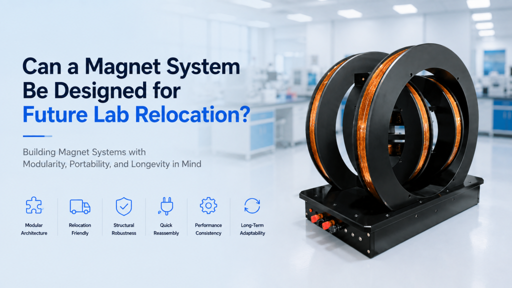
Large laboratory magnet systems are often purchased as if their final installation location will never change.
In reality, research laboratories move.
Universities renovate buildings. Shared facilities relocate equipment. Research groups move to new campuses. New cryostats or optical tables require different layouts. A system purchased for one project may later be reassigned to another laboratory.
For a small benchtop instrument, relocation may be straightforward.
For a large magnet system, it can become an engineering project.
An electromagnet may weigh hundreds of kilograms. A large Helmholtz coil system may occupy several cubic meters. Water cooling, high-current power supplies, control cabinets, field sensors, safety interlocks, sample stages, and measurement electronics may all be distributed around the system.
This raises a useful procurement question:
Can a magnet system be designed from the beginning so that future laboratory relocation is easier, safer, and less disruptive to measurement performance?
In many cases, yes.
But relocation-friendly design requires decisions to be made before the system is manufactured, not when the moving company arrives several years later.
This article explains what should be considered when designing an electromagnet, Helmholtz coil, or integrated magnetic-field platform for future relocation.
1. Relocation Should Be Considered Part of the Equipment Life Cycle
A conventional procurement process often focuses on:
- Required magnetic field
- Field uniformity
- Working space
- Power supply
- Cooling
- Control software
- Delivery time
- Installation
Once acceptance testing is complete, the project is considered finished.
For equipment expected to operate for 10 years or longer, this view is too narrow.
The equipment may experience several phases:
Design → Manufacturing → Delivery → Installation → Operation → Upgrade → Relocation → Recommissioning → Continued Operation
The relocation phase deserves engineering attention just like initial installation.
This is particularly important for:
- Large electromagnets
- Modular Helmholtz coils
- Three-axis magnetic-field systems
- Magnetic shielding systems
- Magnet calibration platforms
- Integrated Hall measurement systems
- Cryogenic magnetic systems
- Custom optical + magnetic experiments
A relocation-friendly design may cost slightly more at the beginning but can significantly reduce future downtime and reconstruction effort.
2. “Movable” and “Designed for Relocation” Are Not the Same
Almost any laboratory instrument can technically be moved.
That does not mean it was designed to be moved.
Consider a large magnetic-field system assembled using:
- Welded frames
- Permanently routed cables
- Custom-cut cooling hoses
- Unlabeled connectors
- Field-sensitive components mounted directly to the frame
- No lifting points
- No defined alignment references
The system can still be dismantled.
But the second installation may become almost a new engineering project.
A relocation-ready system should instead answer several questions from the beginning:
- Where can each module be safely lifted?
- Which components can be separated?
- How are modules aligned again?
- Which cable belongs to which axis?
- Which coolant hose connects where?
- What configuration dimensions must be restored?
- What measurements verify successful recommissioning?
That is a very different design philosophy.
3. Modularization Is Usually the First Design Decision
Large magnet systems become easier to relocate when they are divided into logical modules.
For example, a system might contain:
Magnet Module
- Electromagnet or coil structure
- Pole pieces
- Mechanical frame
Power Module
- Bipolar power supply
- Protection electronics
- Current monitoring
Cooling Module
- Chiller
- Flow sensors
- Manifold
- Filters
Control Module
- Industrial PC
- PLC
- Field controller
- Communication hardware
Measurement Module
- Gaussmeter
- Hall probe
- Temperature controller
- Data-acquisition hardware
Separating functions in this way allows the laboratory to disconnect and transport complete subsystems rather than dismantling every internal component.
4. But More Modules Are Not Automatically Better
There is an important trade-off.
Too little modularity makes relocation difficult.
Too much modularity can reduce mechanical stiffness and reproducibility.
Imagine a large three-axis Helmholtz system split into twenty separate frame sections.
Transportation becomes convenient.
But every relocation now requires twenty mechanical interfaces to be restored accurately.
Each joint introduces possible:
- Position error
- Angular error
- Mechanical movement
- Electrical connection error
The better design is usually:
The smallest number of modules that can still be transported safely through the expected building access route.
Modularity should solve a real logistical problem, not simply maximize the number of removable parts.
5. Building Access Should Influence Magnet Dimensions
Large equipment buyers should ask a surprisingly practical question during specification:
Can this equipment leave the room again?
Consider:
- Door width
- Door height
- Corridor width
- Elevator dimensions
- Elevator load rating
- Stairway geometry
- Loading dock access
- Laboratory entrance
- Ceiling clearance
A magnet frame that is 1,050 mm wide may be perfectly suitable for the experiment.
But if the laboratory door is 1,000 mm wide, future relocation becomes far more complicated.
For custom systems, module dimensions can sometimes be selected around common building-access constraints.
6. Design the System Around a Defined Disassembly Boundary
Relocation-friendly equipment should have an intentional disassembly boundary.
For example:
Things that should remain assembled:
- Precision-aligned magnet core
- Internal coil structure
- Factory-aligned sensor assemblies
Things designed to disconnect:
- Power cables
- Cooling connections
- Sample-stage accessories
- Control cabinets
- External sensors
- Optical hardware
This distinction is important.
Some components should not be casually dismantled simply because bolts are visible.
If a precision magnetic or mechanical assembly depends on factory alignment, keeping it intact during relocation may produce better repeatability than maximizing disassembly.
7. Large Helmholtz Coils Benefit Especially from Modular Frames
Large Helmholtz coil systems are strong candidates for relocation-friendly architecture.
A large coil system may consist of:
- X-axis coil pair
- Y-axis coil pair
- Z-axis coil pair
- Structural frame
- Sample table
- Control electronics
Instead of permanently welding the complete structure, a system may use defined mechanical modules that can be separated and reassembled.
However, the reassembly design must control:
- Coil separation
- Coil concentricity
- Axis alignment
- Orthogonality
- Center position
The main design challenge is not making the system easy to take apart.
It is making it possible to put back together in the same geometry.
8. Repeatable Mechanical Datums Are More Valuable Than Visual Alignment
After relocation, technicians should not have to rebuild the system by saying:
“That looks approximately centered.”
Mechanical design can include repeatable reference features such as:
- Precision locating surfaces
- Dowel pins
- Keyed brackets
- Machined shoulders
- Fixed spacer blocks
- Alignment holes
- Mechanical stops
These features help define where each component belongs.
Bolts provide clamping force.
They should not always be expected to provide precision positioning by themselves.
For systems where coil position affects magnetic-field uniformity, dedicated location features can significantly simplify recommissioning.
9. The Magnet Center Should Have a Physical Reference
Many magnetic experiments depend on knowing the exact magnetic center.
After relocation, researchers often need to recover:
- X center
- Y center
- Z center
- Sample height
- Field direction
A useful system design can provide mechanical reference points related to the magnetic center.
Examples include:
- Center marks
- Reference holes
- Alignment targets
- Laser-reference surfaces
- Fixed stage coordinates
This can help restore the sample stage, Hall probe, cryostat, or optical system after reinstallation.
10. Preserve Critical Dimensions in the Mechanical Documentation
A relocation-ready system should clearly document dimensions such as:
Electromagnet
- Pole gap
- Pole-face alignment
- Sample center
- Base mounting pattern
Helmholtz Coil
- Coil diameter
- Coil spacing
- Axis relationship
- Coil-center coordinates
Three-Axis Systems
- X/Y/Z orientation
- Coordinate convention
- Center point
- Rotation relationship
These dimensions should appear in drawings rather than existing only in the engineer’s memory.
11. Large Electromagnets Need Designed Lifting Points
A large electromagnet should not be lifted from whatever structural feature happens to look strong.
Where heavy equipment is expected to be handled by crane or hoist, lifting strategy should be defined deliberately.
This may include:
- Engineered lifting eyes
- Lifting lugs
- Sling locations
- Defined center of gravity
- Maximum module weight
- Recommended lifting orientation
OSHA guidance for rigging emphasizes rated lifting equipment, adequate attachment points, controlled loads, and consideration of load center of gravity during lifting operations.
The broader engineering lesson applies directly to large laboratory magnets:
Safe lifting should be designed, not improvised.
12. Forklift Access Can Be Designed Into the Base
For some laboratory environments, a forklift or pallet jack may be more practical than an overhead crane.
A large magnet base can sometimes incorporate:
- Fork pockets
- Pallet-jack clearance
- Temporary transport skids
- Removable leveling feet
But forklift handling depends strongly on:
- Weight
- Center of gravity
- Load position
- Stability
OSHA notes that load size, position, weight distribution, and center of gravity directly affect forklift capacity and stability.
Therefore, fork pockets should not simply be cut into a frame without considering structural loading and equipment balance.
13. Mark the Weight of Each Transportable Module
Future laboratory staff may not be the same people who originally purchased the system.
A useful design records the mass of major modules.
For example:
- Magnet assembly: XXX kg
- Power cabinet: XX kg
- Chiller: XX kg
- X-axis coil: XX kg
This information helps later teams select appropriate:
- Cranes
- Forklifts
- Slings
- Dollies
- Transport vehicles
It also prevents technicians from estimating weight visually.
Large electromagnets can be considerably heavier than their external dimensions suggest because of the iron yoke.
14. Transport Locks Can Protect Precision Assemblies
Some components should not move freely during transportation.
Possible examples include:
- Motorized stages
- Sample positioning mechanisms
- Adjustable pole assemblies
- Precision sensor carriages
A relocation-friendly design may include:
- Shipping bolts
- Locking brackets
- Transport clamps
- Removable mechanical restraints
These components prevent vibration during transportation from loading precision stages in ways they were not designed to tolerate.
The storage location of shipping locks should also be documented.
A transport lock that was thrown away after first installation is not very useful five years later.
15. Cooling Connections Should Be Designed for Disconnect and Reconnect
Water-cooled electromagnets introduce another relocation challenge.
Traditional permanent hose routing may involve:
- Hose clamps
- Thread sealant
- Custom hose lengths
- Manually assembled fittings
A relocation-friendly system may instead use appropriately selected:
- Quick-disconnect fittings
- Clearly labeled supply/return connections
- Isolation valves
- Drain points
- Flow-direction markings
The objective is to make disconnection repeatable without introducing unnecessary leak risk.
16. Each Cooling Circuit Should Be Clearly Identified
For large magnets with multiple cooling circuits, labeling matters.
For example:
- Upper coil IN
- Upper coil OUT
- Lower coil IN
- Lower coil OUT
- Power-supply cooling
- Chiller return
After relocation, reversing a flow path or bypassing one coil may result in inadequate cooling even if the chiller itself appears to operate normally.
Permanent labeling is therefore preferable to handwritten temporary tape.
17. Include Drainage in the Relocation Design
Water remaining inside cooling circuits can create problems during transportation.
Depending on conditions, trapped coolant may:
- Leak
- Contaminate crates
- Corrode components
- Freeze during cold transport
- Increase handling weight
A well-designed cooling loop can include accessible drain locations so the magnet can be prepared properly for shipping or storage.
18. High-Current Cables Should Have Defined Disconnect Points
Large electromagnets may use very heavy power cables.
If those cables are permanently integrated into the magnet assembly, relocation becomes awkward.
A more practical architecture can define:
Magnet → High-current connector / terminal → Cable → Power cabinet
This allows the magnet and power supply to travel separately.
However, high-current disconnects must still satisfy:
- Current rating
- Contact resistance
- Mechanical locking
- Polarity identification
- Insulation requirements
Ease of relocation should never reduce electrical safety.
19. Connectors Should Be Keyed Where Possible
Imagine reconnecting twenty similar circular connectors after a laboratory move.
Labeling helps.
But mechanical keying can be even better.
Where practical, connectors can be differentiated by:
- Connector type
- Pin count
- Key orientation
- Physical position
- Permanent labels
The design objective is to make incorrect connection difficult.
This is particularly useful in:
- Three-axis Helmholtz systems
- Multi-sensor systems
- Cryogenic experiments
- Automated magnet platforms
20. Cable Labels Should Survive More Than One Installation
A common problem with laboratory equipment is temporary labeling.
After several years:
- Tape falls off
- Ink fades
- Labels become unreadable
Relocation-friendly systems should ideally use durable identification such as:
- Heat-shrink cable markers
- Engraved labels
- Industrial wire markers
- Printed cable IDs
A consistent numbering system can link each cable to wiring diagrams.
For example:
X-PS-01
could mean:
X-axis → Power Supply → Cable 01.
This may look excessive during initial installation.
It becomes extremely useful during relocation.
21. Separate the Control Cabinet from the Magnet Where Practical
For large installations, mounting all electronics directly onto the magnet structure can make the complete assembly unnecessarily difficult to move.
A more modular architecture may use a separate control cabinet containing:
- Power supplies
- PLC
- Industrial PC
- Safety relays
- Communication equipment
- Power distribution
The magnet assembly then contains only the components that need to remain physically close to the field source.
This has another benefit:
Future electronics upgrades can occur without modifying the mechanical magnet structure.
22. Standardize Interfaces Between Magnet and Control Cabinet
A relocation-friendly cabinet architecture should define interfaces such as:
- AC input
- Magnet output
- Sensor input
- Interlock input
- Cooling control
- Ethernet
- USB
- RS-485
A single interface drawing can then show how the system is reconnected.
This is much more reliable than tracing individual wires after several years.
23. Software Configuration Is Part of Relocation Design
Physical modularity alone is not enough.
The system may depend on:
- Calibration files
- Field-current curves
- PLC settings
- Communication addresses
- Axis definitions
- Safety parameters
- User scripts
All important configuration data should therefore be backed up independently of the control PC.
Ideally, the delivered documentation should identify:
- Which files matter
- Where they are stored
- How they can be restored
- Which software version created them
A future laboratory move often includes a new computer.
The magnet should not become unusable simply because the original PC failed.
24. The Coordinate System Should Be Permanently Defined
This is particularly important for three-axis Helmholtz coils.
The original laboratory may define:
- +X toward the window
- +Y toward the door
- +Z upward
After relocation, those room-based descriptions become meaningless.
A better system defines axes relative to the equipment itself.
For example:
- +X marked on frame
- +Y marked on frame
- +Z marked on frame
The coordinate convention should also match:
- Software
- Power-supply channels
- Field calibration
- Connector labels
This prevents one of the most common relocation errors: a physically correct system with an incorrectly interpreted field direction.
25. Include a Reinstallation Drawing in the Original Documentation
Most equipment manuals describe installation.
Fewer explicitly describe reinstallation after disassembly.
For modular systems, the documentation can include:
- Assembly order
- Module orientation
- Bolt locations
- Alignment features
- Required torque
- Cable routing
- Cooling routing
- Center coordinates
The larger the system, the more valuable this becomes.
The person reinstalling it five years later may never have seen the original installation.
26. Photograph the Factory-Assembled Configuration
Drawings provide dimensions.
Photographs provide context.
Useful factory documentation might include:
- Complete system view
- Rear cable routing
- Cabinet connections
- Cooling manifold
- Sensor position
- Pole gap
- Coil alignment
- Sample stage
These photographs become a visual reference for future relocation.
27. Design Recommissioning Into the System
One of the strongest relocation-friendly features is not mechanical at all.
It is a defined recommissioning procedure.
After reassembly, the laboratory should know exactly what to check.
A basic procedure may include:
- Mechanical inspection
- Electrical continuity
- Cooling flow
- Low-current test
- Field polarity
- Zero-field condition
- Field-current relationship
- Uniformity verification
- Reference measurement
This turns relocation from an open-ended troubleshooting exercise into a controlled engineering process.
28. Preserve Factory Acceptance Test Data
Factory acceptance data provide an extremely valuable post-relocation reference.
For a magnet system, this may include:
- Field vs current
- Maximum field
- Field uniformity
- Coil resistance
- Current stability
- Cooling flow
- Temperature rise
For a Helmholtz system, it may include field measurements along:
- X axis
- Y axis
- Z axis
The new laboratory can then repeat selected tests and compare them with the original values.
29. Design Field Sensors for Repeatable Reinstallation
If a Hall probe or magnetic-field sensor is removed for transportation, the system should ideally allow it to return to a defined position.
Possible features include:
- Probe holder
- Mechanical stop
- Reference slot
- Alignment mark
- Fixed sensor bracket
A sensor moved several millimeters or rotated several degrees may report a different field even if the magnet itself has not changed.
30. Recalibration Strategy Should Be Defined Before Relocation Happens
A system should also define the distinction between:
- Verification
- Adjustment
- Recalibration
After relocation, laboratories may first compare the system against known reference values.
If performance remains within the required tolerance, complete recalibration may not always be necessary.
NIST does not prescribe one universal recalibration interval; it notes that calibration decisions depend on factors including instrument stability, required accuracy, and environmental conditions, and recommends ongoing measurement-assurance programs.
NIST’s metrological traceability guidance also emphasizes documenting the complete measurement process and monitoring measurement-system performance rather than assuming that possession of a calibration certificate alone guarantees future measurement results.
That principle is directly relevant to relocated magnet systems.
31. The New Lab Environment Cannot Be Designed Away Completely
Even a perfectly modular magnet system cannot guarantee identical performance after relocation.
The new laboratory may have different:
- Ambient magnetic field
- Steel structures
- Floor vibration
- Temperature
- Cooling-water conditions
- Electrical grounding
- Mains power quality
- Nearby magnetic equipment
Therefore, relocation-friendly design does not mean:
“Move it and assume nothing changed.”
It means:
Move it efficiently, reconstruct the original geometry reliably, and verify the system quickly.
32. Large Helmholtz Systems Need Special Attention to the New Magnetic Environment
Helmholtz coil systems are often used for:
- Magnetic compensation
- Sensor calibration
- Earth’s-field simulation
- Low-field research
- Vector magnetic fields
In these applications, the ambient field may be comparable to the generated field.
Moving the system from one room to another can therefore change the total magnetic environment.
A relocation plan may require:
- New background-field measurement
- New compensation offsets
- Updated calibration matrices
Mechanical repeatability alone is not sufficient.
33. Large Electromagnets Need Special Attention to Floor Loading
Heavy electromagnets can impose substantial concentrated loads.
Before future relocation, the new laboratory may need to verify:
- Floor capacity
- Equipment footprint
- Load distribution
- Vibration behavior
- Leveling capability
A relocation-friendly base can help distribute load and provide adjustable leveling.
However, building structural requirements remain site-specific and should be evaluated appropriately for the new location.
34. Leveling Features Can Simplify Reinstallation
A large frame may not sit identically on two laboratory floors.
Useful features include:
- Adjustable leveling feet
- Reference level surfaces
- Machine-level positions
- Locking nuts
Leveling can matter for:
- Large Helmholtz coil alignment
- Optical systems
- Sample stages
- Rotation axes
If the system contains sensitive optical or mechanical components, the base frame should provide a repeatable reference plane.
35. Optical Tables and Sample Tables Should Be Separate When Appropriate
An integrated magnetic + optical system may be easier to relocate if the optical platform and magnet frame remain separate modules.
Benefits can include:
- Easier transportation
- Independent vibration control
- Easier optical-table replacement
- More flexible room layout
The important part is having defined alignment references between them.
Otherwise, every relocation requires completely rebuilding the optical geometry.
36. Allow Space for Future System Expansion
Relocation sometimes happens because a laboratory is upgrading the experiment.
A relocation-aware design may therefore reserve:
- Spare cabinet space
- Additional connector positions
- Extra cooling capacity
- Modular sample interfaces
- Adjustable magnet position
This does not mean oversizing every component dramatically.
It means avoiding unnecessarily closed architectures.
A system that can only operate in one exact configuration may become expensive to repurpose later.
37. Spare Connectors and Terminal Capacity Can Extend System Life
Control cabinets for long-life research equipment can benefit from limited spare capacity.
Examples include:
- Spare terminal blocks
- Spare communication ports
- Spare sensor inputs
- Space for another power module
This can make future upgrades or relocation-driven modifications easier without completely rebuilding the cabinet.
38. Choose Standard Components Where Customization Adds No Value
Custom engineering is sometimes unavoidable.
But not every hose, connector, bolt, or cable needs to be proprietary.
Using appropriate standard components can simplify:
- Replacement
- Maintenance
- Future relocation
- International service
A customized magnet can still use standardized peripheral interfaces.
The best system often combines:
custom magnetic engineering + standardized serviceable interfaces.
39. Packaging Can Also Be Designed for Reuse
For very large or expensive systems, reusable transportation fixtures may be worth considering.
Examples include:
- Custom skids
- Transport frames
- Protective covers
- Foam inserts
- Reusable crates
The original packaging should not automatically be discarded if relocation is plausible.
It can also include clearly identified:
- Lifting locations
- Orientation
- Module weight
- Fragile components
This reduces the risk that future movers invent their own handling method.
40. Future Relocation Should Be Discussed During the RFQ Stage
Customers do not need to know the exact future destination.
A few simple questions are enough:
Installation
- Is this expected to remain permanently in one room?
- Could the laboratory relocate during the equipment’s lifetime?
Building Constraints
- Door dimensions
- Elevator access
- Maximum module size
- Maximum practical module weight
Handling
- Crane available?
- Forklift available?
- Pallet jack only?
Reassembly
- Will local technicians reinstall the equipment?
- Is vendor commissioning expected?
These answers can influence the mechanical architecture before manufacturing begins.
41. A Practical Relocation-Friendly Design Checklist
For a large magnet system, consider the following during procurement.
Mechanical Design
- Modular frame where useful
- Defined disassembly boundaries
- Repeatable alignment features
- Marked magnetic center
- Adjustable leveling
- Module weights documented
Handling
- Engineered lifting points
- Defined center of gravity
- Forklift access where appropriate
- Transport locks
- Reusable transport supports
Electrical
- Defined disconnect points
- Permanent cable identification
- Clear polarity
- Keyed connectors where practical
- Separate control cabinet
Cooling
- Labeled IN/OUT circuits
- Disconnectable hoses
- Isolation valves
- Drain points
- Documented flow requirements
Control
- Backup configuration files
- Documented software versions
- Clear axis definition
- Standard communication interfaces
Reassembly
- Mechanical drawings
- Cable diagrams
- Cooling diagrams
- Installation photographs
- Reinstallation instructions
Recommissioning
- Factory baseline data
- Field-current verification procedure
- Field uniformity reference
- Sensor positioning reference
- Reference test protocol
These features turn relocation from an emergency engineering problem into a planned maintenance event.
42. How Cryomagtech Can Approach Relocation-Ready Magnet Systems
For customized magnet and field-generation projects, Cryomagtech can evaluate not only the required magnetic performance but also installation and lifecycle constraints.
Depending on the project, configurations may include:
- Modular Helmholtz coil structures
- Large electromagnet systems
- Adjustable pole assemblies
- Bipolar power supplies
- Independent control cabinets
- Water-cooling systems
- Field measurement
- Modular sample platforms
- Custom mechanical interfaces
- Recommissioning documentation
👉 Product link placeholder: Cryomagtech Magnet & Field Systems – Electromagnets and Helmholtz Coils
For larger customized projects, buyers can provide:
- Laboratory layout
- Door dimensions
- Maximum transport dimensions
- Preferred module weights
- Available lifting equipment
- Expected future installation constraints
These details can be incorporated into the mechanical design before production begins.
43. Key Takeaways
Yes—a magnet system can be designed to make future laboratory relocation significantly easier.
But the key is not simply adding wheels to a heavy system.
A genuinely relocation-ready design considers:
- Module dimensions
- Module weight
- Lifting and handling
- Mechanical datums
- Repeatable alignment
- Electrical disconnects
- Cooling connections
- Cable identification
- Control-cabinet architecture
- Software backups
- Calibration references
- Recommissioning procedures
The most important design principle is:
Do not design only for the first installation. Design for the second installation as well.
For a research system expected to operate for many years, delivery is not the end of the engineering life cycle.
A magnet system that can be safely moved, accurately reassembled, and quickly reverified may provide considerably more long-term value than one optimized only for the day it leaves the factory.
References
1. NIST – Recommended Calibration Interval and Metrological Traceability
NIST explains that recalibration requirements depend on accuracy needs, equipment stability, environmental influences, and measurement-assurance data rather than one universal interval. Its traceability guidance also emphasizes a documented measurement chain and ongoing control of measurement-system performance.
Check source: NIST – Recommended Calibration Interval
Check source: NIST – Metrological Traceability
2. OSHA – Rigging and Heavy Equipment Handling
OSHA requirements and guidance emphasize rated rigging equipment, appropriate attachment points, load stability, and center-of-gravity considerations when heavy loads are lifted or moved. These principles support designing large laboratory equipment with an intentional handling strategy rather than improvising one later.
Check source: OSHA – Rigging Equipment for Material Handling