
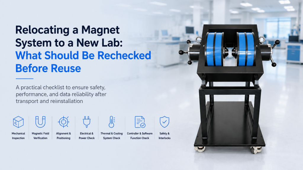
Relocating a magnet system to a new laboratory may look like a logistics project:
disconnect the equipment, move it, reconnect the cables, turn it on, and continue measuring.
For research equipment, that assumption is risky.
A magnet system relocation can change mechanical alignment, electrical grounding, cooling conditions, magnetic-field calibration, sensor position, vibration environment, vacuum integrity, and even the background magnetic field around the experiment.
The system may power on normally while producing measurements that are no longer directly comparable with data collected in the previous laboratory.
This is especially important for:
- Electromagnets
- Helmholtz coil systems
- Hall effect measurement systems
- Vibrating Sample Magnetometers (VSM)
- Cryogenic magnetic measurement systems
- Magnetic-field calibration platforms
- Integrated magnet + optical or electrical experiments
The correct question after relocation is therefore not:
“Does the system still work?”
It is:
“Has the complete measurement chain been verified again under the new laboratory conditions?”
This guide explains what laboratories should recheck before reusing a relocated magnet system.
1. Treat Relocation as a Controlled Recommissioning Process
A magnet system should not normally be treated like an ordinary desktop instrument.
Its performance can depend on several connected subsystems:
- Magnet or coil
- Power supply
- Cooling system
- Field sensor
- Sample stage
- Measurement electronics
- Computer and software
- Vacuum system
- Cryostat
- Temperature controller
- Grounding and shielding
Moving even one part can alter the relationship between these components.
A better relocation workflow is:
Document → Disconnect → Move → Reinstall → Inspect → Verify → Benchmark → Release for use
The final step matters.
Routine research measurements should ideally begin only after the laboratory has established that the relocated system still performs within the required limits.
2. Record the System Condition Before It Leaves the Old Lab
The best relocation verification begins before relocation.
Before dismantling the system, record its working condition.
Useful information includes:
- Maximum magnetic field
- Field versus current relationship
- Zero-current residual field
- Field uniformity
- Sample position
- Pole gap
- Coil spacing
- Power-supply settings
- Cooling-water flow
- Operating temperature
- Vacuum performance
- Sensor calibration information
- Software version
- Instrument communication settings
For measurement systems, also save a representative reference dataset.
Examples include:
- A standard Hall sample
- A reference VSM sample
- A known magnetic specimen
- A calibrated field measurement
- A standard temperature sweep
This creates a baseline for comparison after installation in the new laboratory.
Without baseline data, laboratories may know that the system operates after relocation but have no objective evidence that its performance remained unchanged.
3. Photograph Cable Routing and Mechanical Connections
Complex laboratory systems accumulate practical knowledge that is rarely captured completely in the user manual.
Before disassembly, photograph:
- Cable routing
- Ground connections
- Cooling hoses
- Sensor connections
- Vacuum lines
- Sample-stage orientation
- Pole positions
- Connector labels
- Rack wiring
- Power distribution
Label both ends of every important cable and hose.
For multi-instrument systems, small connection mistakes can produce problems that appear much later as:
- Noise
- communication failure
- unstable temperature
- incorrect sensor reading
- unexpected ground loops
A few minutes of documentation before the move can prevent hours of troubleshooting afterward.
4. Inspect the Magnet Mechanically Before Reuse
A magnet is a heavy electromechanical assembly.
Transportation can affect:
- Pole alignment
- Pole gap
- Coil position
- Mounting bolts
- Yoke alignment
- Support frame
- Sample-stage position
Before energizing the system, inspect for:
- Loose hardware
- Bent brackets
- Damaged connectors
- Cracked insulation
- Coil movement
- Hose damage
- Foreign objects in the pole gap
- Evidence of impact during transportation
For electromagnets with adjustable pole pieces, verify that both pole faces remain correctly aligned.
Even if the magnet was not visibly damaged, a changed mechanical position can affect the field at the sample.
5. Recheck the Pole Gap of an Electromagnet
For an iron-core electromagnet, the pole gap is a fundamental operating parameter.
The magnetic field obtained at a given current depends strongly on the working gap.
After relocation, verify:
- Actual pole-to-pole distance
- Parallelism of pole faces
- Sample position within the gap
- Pole-piece configuration
- Whether removable pole tips were reinstalled correctly
If the original system was characterized at a 20 mm gap but is reassembled at 22 mm, the previous field-current calibration should not automatically be assumed to remain valid.
The same principle applies if a new sample holder or cryostat changes the actual working geometry.
6. Helmholtz Coil Spacing Must Also Be Rechecked
Helmholtz coils appear mechanically simpler than electromagnets, but geometry is central to their performance.
For a conventional Helmholtz pair, coil separation is closely related to coil radius.
If the frame is dismantled during relocation, confirm:
- Coil separation
- Coil parallelism
- Common axis
- Center position
- Coil orientation
- Electrical polarity
A small mechanical misalignment may not prevent the coils from producing a field.
But it can affect:
- Field magnitude
- Field direction
- Uniformity
- Calibration
For three-axis Helmholtz systems, also confirm that the X, Y, and Z coil sets retain their intended orthogonal relationship.
7. Reconfirm Coil Polarity Before Applying Full Current
A rewired coil can be electrically functional while magnetically wrong.
For coil pairs or multi-axis systems, verify:
- Current direction
- Connector polarity
- Series or parallel wiring
- Positive field convention
- Axis assignment
With a Helmholtz pair, incorrect polarity can cause the two coils to oppose rather than reinforce each other.
With a three-axis field system, an incorrect polarity assignment can reverse one coordinate axis and create problems in:
- Vector-field control
- Calibration
- Automated scripts
- Data interpretation
A low-current polarity test should be performed before full-power operation.
8. Do Not Assume the Old Field Calibration Still Applies
One of the most important post-relocation checks is magnetic-field verification.
The relationship between:
Power-supply command → coil current → magnetic field at the sample
should be checked again.
This is particularly important when:
- Magnet geometry was disturbed
- Pole gap changed
- Field sensor was removed
- Sample stage was repositioned
- Cables were replaced
- Power supply was changed
- The system was stored for a long period
NIST emphasizes that metrological traceability depends on the complete documented measurement chain and that simply having an instrument calibrated at some point does not by itself guarantee the validity of future measurement results.
The practical lesson for relocation is straightforward:
previous calibration documentation is valuable, but verification under the reinstalled configuration is still necessary.
9. Check More Than One Magnetic-Field Point
A single check at maximum field is usually not enough.
A better field verification may include:
- Zero current
- Low field
- Medium field
- High field
- Positive field
- Negative field
For example:
- −100%
- −50%
- 0%
- +50%
- +100%
This helps identify:
- Gain changes
- Polarity errors
- Remanence
- Nonlinearity
- Incorrect current scaling
For systems used for precision field sweeps, additional intermediate points may be appropriate.
10. Verify the Zero-Field Condition Again
Moving an iron-core magnet can change its magnetic history.
The new laboratory may also have a different ambient magnetic environment.
Therefore, check the field when commanded current is zero.
Possible contributions include:
- Magnet remanence
- Earth’s magnetic field
- Nearby steel structures
- Other magnets
- Building infrastructure
- Electrical equipment
For soft magnetic materials, Hall measurements, and low-field experiments, a small zero-field offset may be important.
Do not assume:
0 A = 0 T
unless the experiment only requires an approximate field.
11. Recheck Hall Probe Position and Orientation
Field verification itself can be wrong if the field sensor is repositioned incorrectly.
Hall probes are directional sensors.
Lake Shore notes that Hall-probe readings depend on sensor orientation relative to the field and that misalignment introduces measurement error. Its Hall-system documentation gives an example where approximately 5° of angular misalignment produces about 0.4% error and 10° produces about 1.5% error.
After relocation, verify:
- Probe orientation
- Probe height
- Probe lateral position
- Sensitive-axis direction
- Distance from pole faces
- Probe zero
This is especially important when comparing field values measured before and after the move.
A difference may originate from the magnet—or simply from a different probe position.
12. Re-Zero the Field Probe Before Critical Measurements
A Hall probe should generally be checked and zeroed under appropriate conditions before precision field verification.
Lake Shore also warns that local magnetic fields—including Earth’s field or remanence from an electromagnet—can affect the zeroing process if the probe is not placed in a suitable zero-field environment.
After relocation:
- Allow electronics to reach normal operating conditions
- Inspect the probe for transportation damage
- Confirm calibration information
- Zero the probe correctly
- Verify its orientation
Hall probes can be mechanically delicate.
Transportation damage or strain on the sensor can affect calibration even when the probe still produces a reading.
13. Recheck Field Uniformity if the Mechanical Geometry Changed
Maximum center field is only one specification.
Many experiments depend on field uniformity over a defined sample region.
Examples include:
- Helmholtz coil experiments
- Large Hall samples
- Magnetic sensor calibration
- MOKE scanning
- VSM sample motion
- Multi-sample systems
If the magnet or coil structure was dismantled, consider rechecking field values at:
- Center
- +X / −X
- +Y / −Y
- +Z / −Z
The number and spacing of verification points should match the actual required uniform region.
A system can reproduce its center field while its uniformity has changed because one component is slightly misaligned.
14. The New Lab’s Magnetic Background May Be Different
Laboratory relocation changes the magnetic environment surrounding the experiment.
Potential sources include:
- Structural steel
- Elevators
- HVAC motors
- Transformers
- Power cables
- Nearby laboratory magnets
- Moving vehicles
- Metal furniture
- Reinforced concrete
For a 1 T electromagnet, these disturbances may appear insignificant at high field.
For experiments operating at:
- µT levels
- Earth’s-field range
- Small compensation fields
- Low-coercivity magnetic states
they can become important.
Before recommissioning a sensitive Helmholtz or magnetic compensation system, measure the ambient field in the new installation location.
For sensitive work, measure all three field components if possible.
15. Check Whether Nearby Ferromagnetic Objects Have Changed the Field
A new laboratory may place the magnet close to objects that were absent previously.
Examples include:
- Steel optical tables
- Metal cabinets
- Gas cylinders
- Tool carts
- Reinforced walls
- Structural columns
Ferromagnetic materials can distort the local magnetic field.
This is especially relevant for:
- Open Helmholtz coils
- Large uniform-field systems
- Calibration setups
- Low-field measurements
If magnetic-field mapping is important, perform it with the laboratory in its normal operating configuration—not in an artificially empty room.
16. Recheck Electrical Power Before Connecting the System
Laboratories should verify the electrical supply rather than assuming that the new room is equivalent to the old one.
Confirm:
- Rated AC voltage
- Frequency
- Maximum current
- Circuit capacity
- Protective earth
- Connector type
- Breaker rating
High-power electromagnet supplies can place substantial load on laboratory circuits.
A system designed for 230 VAC should not simply be connected wherever a physically compatible socket happens to exist.
For imported equipment, also verify that no temporary transformer or adapter has accidentally become part of the permanent installation without being included in the original system design.
17. Grounding and Shielding Must Be Rebuilt Carefully
A relocated experiment often gets reconnected differently from the original installation.
That can create new ground loops.
Symptoms may include:
- 50/60 Hz noise
- Unstable Hall voltage
- Noisy temperature sensors
- MOKE detector noise
- Communication problems
- Unexplained offsets
This matters particularly for:
- Hall systems
- Cryogenic measurements
- Low-voltage transport measurements
- Optical detectors
- Lock-in amplifiers
Do not assume that “everything is grounded” is automatically good.
The more useful question is:
Is the grounding topology intentional?
Document which components connect to protective earth, signal ground, chassis ground, shields, and cryostat ground.
18. Inspect High-Current Cables and Terminals
Electromagnets may use cables carrying significant DC current.
Before reuse, inspect:
- Cable insulation
- Connector tightness
- Terminal oxidation
- Crimp quality
- Mechanical strain
- Cable routing
A connection that became slightly loose during transportation can produce:
- Additional resistance
- Local heating
- Voltage drop
- Unstable current
- Connector damage
After recommissioning, monitor cable and terminal temperature during an initial high-current test.
Any unexpectedly hot connection deserves investigation.
19. Water-Cooled Electromagnets Need a Full Cooling Check
If the magnet is water cooled, relocation introduces another system that must be recommissioned.
Check:
- Hose connections
- Flow direction
- Flow rate
- Water pressure
- Chiller capacity
- Coolant quality
- Leaks
- Filters
- Interlocks
Do not immediately apply full magnetic-field current after reconnecting the cooling loop.
First confirm that coolant is actually circulating through the required channels.
A pump running does not necessarily mean that the magnet is receiving adequate flow.
20. The New Cooling-Water Environment May Be Different
Even if the same chiller is moved with the magnet, the new installation can change:
- Hose length
- Height difference
- Pressure drop
- Ambient temperature
- Ventilation
If the system uses building cooling water rather than a dedicated chiller, water quality and pressure can also change between laboratories.
For long-term reliability, confirm that the cooling conditions still match the magnet and power-supply requirements.
21. Recheck Fan and Airflow Clearance
Air-cooled magnets and electronic power supplies require adequate ventilation.
After relocation, avoid installing them:
- Against walls
- Inside poorly ventilated cabinets
- Directly beside heat sources
- With blocked fan intakes
Reduced airflow can result in:
- Higher coil temperature
- Power-supply derating
- Field drift
- Reduced continuous duty cycle
- Premature component failure
A system that worked continuously in an open laboratory may behave differently when installed beneath a crowded bench.
22. VSM Systems Need a New Vibration Assessment
A VSM intentionally vibrates the sample to detect magnetic moment.
That does not mean external vibration is irrelevant.
A new laboratory may be close to:
- Mechanical pumps
- Elevators
- HVAC equipment
- Hallways
- Heavy machinery
- Building vibration sources
Quantum Design’s installation guidance for a SQUID VSM system specifically identifies floor vibration, ambient conditions, power, ventilation, and cooling as installation considerations.
After relocation, run a known reference sample and compare:
- Signal noise
- Loop smoothness
- Repeatability
- Background
- Centering behavior
Do not rely only on the fact that the VSM completes its measurement sequence without an error message.
23. Recheck VSM Sample Centering
VSM measurements depend on the position of the sample relative to the pickup coils.
Transportation may change:
- Sample rod alignment
- Mechanical reference position
- Motor position
- Pickup geometry
Before returning to routine measurements:
- Run the centering procedure
- Verify known reference samples
- Check reproducibility after remounting
- Confirm sample-holder alignment
If the system includes multiple sample holders, check the holders that are actually used most often rather than assuming one successful test validates every fixture.
24. Hall Systems Need an Electrical Baseline Test
For a Hall effect measurement system, relocation can affect low-level electrical measurements even when the magnet is unchanged.
Recheck:
- Sample current source
- Voltage measurement
- Contact switching
- +B/−B operation
- +I/−I reversal
- Noise floor
- Zero-field offset
- Data calculation
A useful recommissioning test is to measure a previously characterized sample under the same:
- Current
- Magnetic field
- Temperature
- Geometry
- Calculation method
Compare:
- Resistivity
- Carrier concentration
- Mobility
- Hall coefficient
- Conductivity type
Significant differences should be investigated before new research data are accepted.
25. Cryogenic Systems Require More Than a Magnet Check
Relocating a low-temperature magnet system adds several additional risks.
Check:
- Vacuum seals
- O-rings
- Flanges
- Vacuum feedthroughs
- Temperature sensors
- Heater wiring
- Thermal anchoring
- Cold finger
- Cryocooler connections
- Vacuum pump performance
Transportation can disturb a seal that looked perfectly reliable before the move.
Before installing valuable samples, perform a complete empty-system test if practical.
26. Verify Vacuum Performance Again
A cryostat that reaches vacuum is not necessarily performing as before.
Compare:
- Base pressure
- Pump-down time
- Leak rate
- Pressure stability
A slower pump-down may indicate:
- Loose connection
- Damaged seal
- Contamination
- Moisture
- Pump issue
Poor vacuum can affect:
- Base temperature
- Temperature stability
- Cooldown time
- Sample heating
- Condensation risk
For cryogenic magnet systems, vacuum performance should be part of recommissioning.
27. Recheck Temperature Sensor Readings
Temperature measurement is another calibration chain that should not simply be assumed unchanged.
Confirm:
- Sensor identity
- Sensor connector
- Calibration curve
- Input channel
- Excitation setting
- Units
- Heater configuration
If sensors were disconnected during relocation, verify that they were returned to the correct controller channels.
This is especially important when several sensors use similar connectors.
A sensor connected to the wrong calibration curve can produce plausible-looking but incorrect temperatures.
28. Test Temperature Control Before Running a Full Experiment
For temperature-controlled systems, perform a controlled test at several setpoints.
For example:
- Room temperature
- Intermediate temperature
- Near the lower operating range
Check:
- Stability
- Overshoot
- Settling time
- Heater output
- Sensor consistency
If a cryostat was mechanically disturbed, temperature-control parameters that were previously optimized may no longer produce identical behavior.
29. Check Software, Drivers, and Communication Interfaces
Relocation often comes with another change:
a new computer or network environment.
Verify:
- Instrument drivers
- Serial-port assignments
- USB device names
- Ethernet addresses
- Software licenses
- Calibration files
- Configuration files
- Automation scripts
- Data paths
A system may communicate successfully while using the wrong configuration file.
Keep copies of:
- Original installation package
- Instrument configuration
- Calibration files
- User scripts
- Known working software version
Avoid upgrading every piece of software during relocation unless there is a specific reason.
Changing laboratory, computer, operating system, drivers, and software simultaneously makes troubleshooting unnecessarily difficult.
30. Recheck Safety Interlocks
Safety systems should be deliberately tested after reconnection.
Depending on the system, these may include:
- Cooling-flow interlock
- Overtemperature protection
- Overcurrent protection
- Emergency stop
- Door or enclosure interlock
- Cryogenic pressure protection
- Vacuum protection
- Water-leak alarm
Do not assume that an interlock works because its cable is connected.
Verify the actual protective response according to the equipment’s documented procedure.
31. Run the System at Low Power First
The first test after relocation should normally not be a maximum-field experiment.
A staged recommissioning is safer.
Stage 1
- Power electronics only
- Check communication
- Check sensors
Stage 2
- Low magnet current
- Confirm polarity
- Confirm field response
Stage 3
- Intermediate current
- Check heating and cooling
Stage 4
- Full operating field
- Monitor temperature and stability
This helps identify installation problems before large amounts of energy are applied to the magnet.
32. Recheck Continuous-Duty Performance
A system can pass a short magnetic-field test and still fail during long operation.
For electromagnets, verify behavior during a realistic continuous run.
Monitor:
- Coil temperature
- Cooling-water temperature
- Current stability
- Magnetic-field stability
- Power-supply temperature
If the new laboratory has:
- Higher ambient temperature
- Poorer airflow
- Different cooling water
continuous-duty performance may differ from the previous installation.
33. Use a Reference Sample Before Measuring New Research Samples
One of the most effective recommissioning tools is a known sample.
For example:
Hall System
Use a previously characterized semiconductor sample.
VSM
Use a magnetic reference sample with a stable hysteresis loop.
MOKE
Use a stable thin film with a known coercive field.
Field System
Use a calibrated gaussmeter and previously documented field points.
Cryogenic System
Repeat a known temperature profile or sample measurement.
The exact purpose is not necessarily to reproduce every historical value perfectly.
It is to identify unexpected changes before they become mixed with new scientific results.
34. Compare Old and New Data Quantitatively
Do not rely only on visual statements such as:
“The curves look approximately the same.”
Compare relevant values numerically.
Examples include:
- Maximum field
- Zero-field offset
- Field at selected currents
- Coercivity
- Saturation moment
- Carrier concentration
- Mobility
- Resistivity
- Base temperature
- Temperature stability
- Vacuum level
Define acceptable deviation according to the experiment.
For some applications, 2% may be irrelevant.
For others, 0.2% may already matter.
35. Decide Whether Verification or Full Recalibration Is Needed
Not every relocation automatically requires factory recalibration of every component.
The correct decision depends on:
- Required measurement accuracy
- Equipment stability
- Transportation conditions
- Whether sensors were disturbed
- Whether mechanical geometry changed
- Quality-system requirements
- Manufacturer recommendations
NIST does not prescribe one universal recalibration interval; it states that appropriate intervals depend on factors including accuracy requirements, instrument stability, and environmental conditions, and recommends measurement-assurance approaches such as comparisons and performance monitoring.
This principle also makes sense after relocation.
A laboratory may begin with verification against known references.
If verification fails or the required uncertainty cannot be demonstrated, recalibration may then be appropriate.
36. Calibration and Verification Are Not the Same Thing
These terms are often used interchangeably in laboratories, but they serve different purposes.
Verification
Checks whether the system still meets a required criterion.
Example:
“At 10 A, measured field remains within ±1% of the previous validated value.”
Calibration
Establishes the relationship between the instrument indication and reference values under defined conditions.
Example:
“Create a new field-versus-current calibration using a calibrated magnetic-field reference.”
NIST distinguishes calibration, adjustment, and verification as different ways to characterize measuring systems.
For many relocations, verification is the sensible first step.
If the system no longer meets the required criteria, recalibration or service becomes the next step.
37. Keep a Relocation and Recommissioning Record
For shared university laboratories and research facilities, create a simple record containing:
- Previous laboratory
- New laboratory
- Move date
- Equipment serial numbers
- Components disconnected
- Mechanical settings
- Calibration status
- Verification results
- Reference samples used
- Problems found
- Corrective actions
- Date released for normal use
This becomes valuable when someone asks six months later:
“Why did the baseline change after the lab renovation?”
Without documentation, that question may be impossible to answer.
38. A Practical Magnet System Relocation Checklist
Before returning the system to normal research use, confirm the following.
Mechanical
- Magnet securely mounted
- Pole gap verified
- Coil spacing verified
- Sample stage aligned
- No shipping damage
Electrical
- Correct AC power
- Protective earth verified
- High-current connections tight
- Correct coil polarity
- Grounding and shielding restored
Magnetic
- Zero field checked
- Positive field verified
- Negative field verified
- Field-current relationship checked
- Uniformity checked where necessary
Cooling
- Water flow verified
- Chiller operating correctly
- No leakage
- Airflow unobstructed
Measurement Sensors
- Hall probe inspected
- Probe orientation verified
- Probe zero checked
- Calibration information confirmed
Cryogenic / Vacuum
- Vacuum integrity verified
- Temperature sensors confirmed
- Heater operation checked
- Base temperature tested
Software
- Drivers installed
- Communication verified
- Calibration files restored
- Automation sequences tested
- Data export checked
Performance
- Reference sample measured
- Results compared with historical data
- Deviations documented
Only after these checks should routine measurement resume.
39. How Cryomagtech Supports Magnet Systems Throughout Their Operating Life
Cryomagtech magnet and magnetic measurement systems can involve combinations of:
- Electromagnets
- Helmholtz coils
- Bipolar power supplies
- Hall effect measurement systems
- VSM systems
- Magnetic-field measurement
- Cryogenic sample environments
- Temperature control
- Vacuum integration
When a laboratory relocates an existing system, the important question is not simply whether individual instruments survived transportation.
The interfaces between them should also be verified.
👉 Product link placeholder: Cryomagtech Magnet & Field Systems – Electromagnets and Helmholtz Coils
For integrated measurement platforms:
👉 Product link placeholder: Cryomagtech Hall, VSM and Cryogenic Magnetic Measurement Systems
For laboratories planning a future relocation, documenting the original installation parameters before the move can make recommissioning significantly easier.
40. Key Takeaways
Relocating a magnet system should be treated as a recommissioning event, not simply a transportation event.
Before reuse, laboratories should recheck:
- Mechanical geometry
- Electromagnet pole gap
- Helmholtz coil alignment
- Coil polarity
- Magnetic-field calibration
- Zero-field offset
- Hall-probe position
- Field uniformity
- Ambient magnetic environment
- Electrical grounding
- High-current connections
- Cooling performance
- Vacuum integrity
- Temperature measurement
- Vibration environment
- Software configuration
- Safety interlocks
- Reference-sample performance
The most important distinction is this:
A system that powers on is operational.
A system that reproduces verified reference performance is ready for measurement.
For university laboratories and shared research platforms, that difference matters.
Because after relocation, the goal is not merely to reuse the equipment.
It is to trust the data produced by it again.
References
1. NIST – Metrological Traceability and Calibration Guidance
NIST explains that trustworthy measurement results depend on a documented measurement chain and that calibration status alone does not automatically guarantee the validity or traceability of subsequent measurements. NIST also recommends determining calibration and verification needs according to accuracy requirements, equipment stability, and environmental conditions.
Check source: NIST – Metrological Traceability
Check source: NIST – Recommended Calibration Interval
2. Lake Shore Cryotronics – Hall System Probe Accuracy and Orientation
Lake Shore’s Hall measurement documentation explains why Hall-probe positioning, orientation, zeroing, temperature, and mechanical handling affect magnetic-field measurement accuracy—factors that should be rechecked when a magnetic measurement system is reinstalled.
Check source: Lake Shore – Hall System Manual