
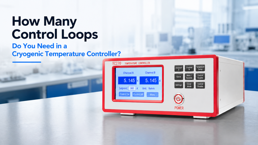
When buyers compare cryogenic temperature controllers, they often begin with the number of sensor inputs:
- Two sensor inputs
- four sensor inputs
- eight measurement channels
- optional scanner channels
But the number of temperature inputs does not tell you how many parts of the cryogenic system can be regulated independently.
A controller may monitor four or eight temperature sensors while providing only one or two independent closed-loop heater controls.
That difference matters.
A sensor input tells you what a temperature is. A control loop actively changes heater power to maintain a selected temperature.
For cryostats, Hall measurement systems, low-temperature sample stages, radiation shields, magnet-integrated platforms, and multi-zone thermal systems, the number of cryogenic temperature controller control loops can directly affect:
- How many thermal stages can be stabilized independently
- whether the sample and radiation shield can use separate setpoints
- whether two samples can run at different temperatures
- how cooldown and warm-up sequences are automated
- whether one heater disturbs another thermal zone
- whether future upgrades require another controller
- how much heater power is available for each stage
This article explains how to determine whether your application needs one, two, or several control loops—and why counting temperature channels alone can lead to the wrong purchase.
1. What Is a Cryogenic Temperature Control Loop?
A temperature control loop connects three main elements:
- A temperature sensor measures a thermal stage.
- The controller compares the measured temperature with a setpoint.
- A heater output adds power to reduce the difference between the measured temperature and the setpoint.
In most cryogenic controllers, this feedback process uses PID control:
- P — Proportional: Responds to the current temperature error.
- I — Integral: Corrects accumulated error over time.
- D — Derivative: Responds to the rate at which the temperature is changing.
Lake Shore defines a control loop as the pairing of a temperature input with a heater output. NIST also provides practical PID guidance for cryogenic sample-environment systems, including the use of different PID settings at different temperature regions.
2. Sensor Inputs and Control Loops Are Not the Same
This is the most important distinction.
A Sensor Input Can:
- Read a temperature sensor
- display temperature
- record temperature
- trigger an alarm
- support data logging
- provide feedback to a selected control output
A Control Loop Can:
- Select a sensor as its control input
- compare the sensor reading with a setpoint
- calculate heater output
- regulate one thermal zone
- apply PID settings
- follow a temperature ramp
- change settings across temperature zones
A controller may therefore have:
- Four sensor inputs
- two independent PID heater loops
- additional analog or monitor outputs
For example, Lake Shore’s Model 336 is specified with four standard sensor inputs but two independent powered PID heater outputs. This illustrates why input count and closed-loop count must be reviewed separately.
3. Heater Outputs and Control Loops Are Also Not Always Identical
A controller may list several outputs, but not every output necessarily provides the same function.
Possible outputs include:
- Powered heater output
- low-power heater output
- analog voltage output
- alarm relay
- warm-up output
- manually controlled output
- external power-supply programming output
- grouped heater output
Buyers should confirm whether each output can operate as:
- An independent closed-loop PID controller
- open-loop manual power only
- monitor or alarm output
- analog control signal for external equipment
- a member of a grouped heating function
Do not assume that “four outputs” always means “four identical independent high-power PID loops.”
4. One Control Loop: The Simplest Architecture
One control loop is often enough when the cryogenic system has one primary controlled stage.
Examples include:
- One sample stage in a simple cryostat
- one cold plate
- one temperature-controlled sensor platform
- one cryogenic Hall sample holder
- one small material-characterization stage
- one calibration block
- one controlled insert inside an otherwise passive cryostat
A typical arrangement is:
- Sensor A mounted close to the sample
- Heater 1 mounted on the sample stage
- Control Loop 1 uses Sensor A to regulate Heater 1
- Other sensors are used only for monitoring
This is a practical and economical configuration when all critical components are thermally linked closely enough to follow the same controlled temperature.
5. When One Loop Is Usually Sufficient
One control loop may be appropriate when:
- Only one temperature setpoint is needed.
- The sample and stage are strongly thermally coupled.
- The radiation shield does not require active control.
- There is only one heater.
- Temperature gradients are not critical.
- The system does not contain independently heated samples.
- Warm-up can be performed using the same heater.
- Future thermal expansion is unlikely.
- The experiment does not require simultaneous independent temperatures.
One loop can still use multiple sensors.
For example:
- One sensor controls the stage.
- A second sensor monitors the sample.
- A third sensor monitors the radiation shield.
- A fourth sensor monitors the cold head.
Only the stage sensor is used for feedback.
6. Monitoring More Sensors Does Not Create More Thermal Zones
Suppose a controller has four inputs connected to:
- Cold head sensor
- radiation shield sensor
- sample stage sensor
- sample sensor
This does not mean the controller can maintain four independent temperatures.
If it has only one heater loop, it can actively regulate only one heater-controlled zone at a time.
The remaining inputs may provide valuable information about:
- Thermal gradients
- cooldown progress
- abnormal heat load
- sample-to-stage temperature difference
- shield performance
- system safety
Monitoring is useful—but it is not independent control.
7. Two Control Loops: A Common Cryogenic Configuration
Two independent loops are useful when the system has two thermal stages that need different heater actions or setpoints.
Typical configurations include:
Sample Stage + Radiation Shield
- Loop 1 controls the sample stage.
- Loop 2 controls the radiation shield.
Sample Stage + Variable-Temperature Insert
- Loop 1 regulates the sample platform.
- Loop 2 regulates another stage in the insert.
Sample + Reference Stage
- Loop 1 controls the sample.
- Loop 2 controls a reference sensor or calibration block.
Main Heater + Independent Warm-Up Stage
- Loop 1 performs precision sample control.
- Loop 2 manages a separate warm-up or auxiliary heater.
Two-loop controllers are common because many cryogenic systems contain one precision-controlled sample zone plus one supporting thermal zone.
8. Sample Stage and Radiation Shield Control
A radiation shield helps reduce radiative heat transfer to the colder stage.
In a simple system, the shield may follow the cold head passively.
In more demanding systems, the shield may have:
- Its own temperature sensor
- its own heater
- its own setpoint
- its own PID parameters
- a different thermal response from the sample stage
Separate control can be valuable when:
- Shield temperature affects sample stability.
- Optical windows create additional radiative heat load.
- The shield must follow a defined temperature program.
- Temperature gradients must be limited.
- The sample stage and shield warm at different rates.
- Controlled warm-up is required.
If both stages have heaters but the controller has only one true PID loop, they cannot be regulated independently in the normal sense.
9. Independent Control Means Independent Feedback
Two heaters do not automatically provide two independent loops.
For true independent control, each thermal zone normally needs:
- A suitable control sensor
- a heater
- an independent output
- its own setpoint
- its own PID parameters
- sufficient heater power
- software capable of running both loops simultaneously
A single sensor driving two heaters together is still one feedback loop, even if the heat is distributed across two locations.
10. Heater Groups Are Not the Same as Multiple Loops
Some controllers can group several physical heaters into one virtual output.
This can be useful when:
- A large stage needs distributed heating.
- Several heaters must act together.
- One heater cannot provide enough power.
- Uniform heating is improved by several heater locations.
Lake Shore’s Model 346 documentation describes heater groups that pair one temperature input with multiple physical heaters. The grouped heaters operate together as one control loop rather than becoming several independently regulated zones.
This distinction is important:
- Four heaters controlled together from one sensor = one loop.
- Four heaters controlled independently from four sensors = four loops.
11. Distributed Heating Can Still Use One Loop
Consider a large calibration plate with four heaters mounted around its perimeter.
If all four heaters are intended to maintain one common plate temperature, a grouped one-loop arrangement may be appropriate.
Advantages may include:
- More total heating power
- improved heat distribution
- simplified setpoint management
- fewer independent tuning requirements
- reduced risk of heaters fighting one another
But if different plate areas must hold different temperatures, grouped heating will not provide true multi-zone control.
12. When Three or More Control Loops May Be Needed
More than two loops may be justified when the system includes several independently regulated thermal regions.
Examples include:
- Sample stage
- radiation shield
- cryostat window stage
- reference sample
- detector stage
- secondary sample stage
- controlled thermal gradient
- multi-zone calibration platform
- several independently heated devices
- complex warm-up architecture
A multi-loop controller may reduce the need for several separate instruments.
However, each additional loop adds:
- Sensors
- heaters
- wiring
- feedthrough pins
- PID tuning
- software configuration
- interaction risk
- FAT requirements
Additional loops should solve defined thermal requirements rather than being added only because more sounds better.
13. Multi-Sample Systems
A cryogenic platform may support two or more samples.
The correct loop count depends on how those samples are used.
Same Temperature, Same Stage
If all samples are mounted on one thermally uniform stage and must remain at the same temperature, one loop may be enough.
Same Nominal Temperature, Weak Thermal Coupling
If samples sit on separate holders with meaningful temperature differences, more sensors may be needed. Independent loops may or may not be necessary, depending on the allowed gradient.
Different Temperatures Simultaneously
If Sample A must remain at 50 K while Sample B remains at 100 K, each sample generally needs:
- Its own thermal isolation
- its own sensor
- its own heater
- its own control loop
The mechanical and thermal design must support those different temperatures. A controller alone cannot create thermal independence if the stages are strongly coupled.
14. Two Loops Cannot Overcome Poor Thermal Design
Adding control loops does not automatically solve thermal problems.
Independent control requires appropriate physical design, including:
- Thermal isolation between stages
- controlled heat paths
- sufficient heater placement
- suitable sensor placement
- realistic cooling capacity
- manageable thermal gradients
- stable mechanical interfaces
If two heaters act on the same highly conductive copper block, two controllers may compete rather than create two useful temperatures.
Control architecture and cryostat design must be evaluated together.
15. Control Loops Can Interact
Even physically separate thermal stages may influence each other.
For example:
- Heating the sample stage warms the shield.
- Heating the shield reduces the cooling available to the sample.
- One stage radiates heat to another.
- Wiring transfers heat between stages.
- A common cold head has limited cooling capacity.
If two PID loops react to the same thermal disturbance, they can:
- Oscillate
- overshoot
- continually compensate against each other
- take longer to stabilize
- produce unstable heater power
The buyer should ask whether the multi-loop configuration has been tested as an integrated thermal system.
16. Sensor Placement Determines What the Loop Controls
A control loop regulates the temperature measured by its selected sensor.
It does not directly regulate every object nearby.
If the control sensor is mounted on the cold head, the controller stabilizes the cold-head sensor temperature.
The sample may still be warmer because of:
- Poor thermal contact
- sample-current heating
- optical illumination
- heater geometry
- wiring heat leak
- radiation
- fast temperature ramps
For precision experiments, the control sensor should be placed where it represents the thermal quantity that matters.
17. Control Sensor vs. Monitor Sensor
A useful cryogenic system may use both.
Control Sensor
Used as feedback for the PID loop.
It should normally have:
- Stable thermal contact
- suitable calibration
- low delay relative to the heater
- an appropriate operating range
- a location relevant to the controlled stage
Monitor Sensor
Used to observe another location.
It may reveal:
- Sample-to-stage gradients
- cold-head behavior
- shield temperature
- excessive heat load
- incomplete equilibration
- abnormal cooldown
A monitor sensor may be more physically representative of the sample but too slow or noisy to serve as the best control input.
18. The Sensor Nearest the Sample Is Not Always the Best Control Sensor
It may seem obvious to use the sensor closest to the sample for feedback.
But this can create poor control if:
- The sensor has slow thermal response.
- The sensor is weakly coupled to the heater.
- The sample mount changes often.
- Signal noise affects the control reading.
- The sensor is temporarily removed with the sample.
- There is a long thermal delay between heater and sensor.
A stage sensor close to the heater may provide more stable PID control, while a second sensor monitors the sample temperature.
The correct choice depends on the thermal response, not only physical distance.
19. One Loop Can Switch Between Sensor Inputs
Some controllers allow one heater loop to use different control sensors at different temperature regions.
For example:
- A diode sensor may be used at higher temperatures.
- An NTC resistance sensor may be used at lower temperatures.
- Control may switch automatically when a zone boundary is crossed.
Lake Shore documentation describes zone functions that can change the control input, PID values, heater range, ramp rate, and other settings as temperature moves through predefined regions.
This improves wide-range control but does not create another independent thermal loop.
20. Temperature Zones Are Not Additional Control Loops
A controller may support ten temperature zones.
That does not mean it has ten independent loops.
Zones are sets of control parameters used across different temperature ranges.
A zone may change:
- P value
- I value
- D value
- heater range
- output limit
- control sensor
- ramp rate
- manual output
The system may still be regulating only one thermal stage with one heater output at any moment.
21. Why PID Settings Change with Temperature
Cryogenic systems do not have one constant thermal response over the full temperature range.
As temperature changes:
- Cooling capacity changes.
- Material heat capacity changes.
- Thermal conductivity changes.
- Heater effectiveness changes.
- Sensor sensitivity changes.
- Radiation heat load changes.
- Thermal time constants change.
One PID setting may work well at 300 K but overshoot or respond too slowly at 10 K.
NIST’s cryogenic PID guidance notes the use of PID zones to apply different heater powers and tuning conditions at different setpoints to reduce overshoot or undershoot.
22. More Temperature Ranges Do Not Necessarily Require More Loops
A laboratory may need control from 4 K to 400 K.
That wide range may require:
- More than one sensor type
- several PID zones
- automatic sensor switching
- several heater-power ranges
- careful ramp programming
But it may still use one physical heater loop if only one stage is controlled.
Loop count is determined by the number of independently controlled thermal zones—not by the width of the temperature range.
23. Heater Power Matters as Much as Loop Count
A controller may have the correct number of loops but insufficient heater power.
For each loop, buyers should define:
- Heater resistance
- maximum heater current
- maximum heater voltage
- required heater power
- low-power resolution
- output noise
- heater wiring capacity
- temperature range
- expected thermal load
Lake Shore’s Model 336, for example, provides two powered heater loops with different maximum power ratings. Its documentation also shows that output capability depends on heater resistance and selected output range.
Two loops with the wrong power levels may be less useful than one properly matched loop.
24. The Main Loop and Auxiliary Loop May Need Different Power
A common configuration is:
Main Sample Loop
May require:
- Fine low-power control
- low output noise
- high resolution
- stable operation close to base temperature
Shield or Warm-Up Loop
May require:
- More total power
- faster warm-up
- less demanding short-term precision
- control of a larger thermal mass
In another system, the requirements may be reversed.
The quotation should not merely state “two heater outputs.” It should provide the power and current capability of each output.
25. Low-Power Resolution Matters Near Base Temperature
At very low temperature, the stage may require only a small amount of heater power.
If the minimum controllable output step is too large, the loop may:
- Oscillate
- overshoot
- alternate between too hot and too cold
- fail to maintain tight stability
Useful controller features may include:
- Multiple heater-power ranges
- low-noise output
- output limits
- fine current resolution
- suitable heater resistance
- adjustable PID parameters
A high maximum heater power does not automatically mean good low-temperature control.
26. External Heater Power Supplies
Some thermal stages require more power than the controller can provide directly.
A controller may then use an analog output to program:
- An external current source
- an external power supply
- a power amplifier
- a larger heater driver
The buyer should confirm:
- Whether the analog output supports closed-loop operation
- output voltage range
- isolation
- external supply compatibility
- failure behavior
- heater-current measurement
- safety limits
- interlock requirements
An external power stage can extend heater capability, but it also expands the system and responsibility boundary.
27. Open-Loop Heater Output Is Not the Same as Closed-Loop Control
In open-loop operation, the controller applies a chosen heater-power level without continuously adjusting it from temperature feedback.
Open-loop output may be useful for:
- Initial cooldown assistance
- controlled warm-up
- approximate background heating
- testing heater wiring
- special experiment sequences
But it does not automatically maintain a stable temperature as the heat load changes.
Buyers who require temperature regulation should confirm that the required outputs support closed-loop PID operation.
28. Warm-Up Control
Cryogenic systems may need a controlled warm-up after the experiment.
Possible methods include:
- Using the main sample heater
- using a dedicated warm-up heater
- coordinating several heaters
- applying manual output
- following a programmed temperature ramp
- switching heaters off near room temperature
A separate warm-up loop may be useful when:
- The system has a large thermal mass.
- Different stages must warm together.
- Condensation risk must be controlled.
- Sample and shield temperatures must remain close.
- The main precision heater is too small.
However, a dedicated warm-up loop is not always necessary. Some controllers can coordinate several outputs or use programmed warm-up functions, depending on architecture.
29. Controlled Thermal Gradients
Some experiments intentionally create a temperature difference.
Examples include:
- Thermoelectric measurements
- Seebeck coefficient measurements
- thermal conductivity studies
- gradient-dependent transport
- heat-flow calibration
These applications may require:
- Two independently controlled heaters
- two or more temperature sensors
- thermal isolation
- known sensor spacing
- differential temperature measurement
- coordinated loop operation
A two-loop controller may be required, but the full thermal platform must be designed for stable gradient generation.
30. Hall Systems and Control Loop Planning
A cryogenic Hall system may include sensors at:
- Cold head
- radiation shield
- sample stage
- sample holder
- cryostat body
The correct loop architecture depends on the measurement.
Basic Hall Configuration
- One sample-stage sensor
- one sample-stage heater
- one PID loop
- additional monitor sensors
Higher-Accuracy Configuration
- Loop 1 controls the main stage.
- Loop 2 controls the radiation shield or sample holder.
- A separate sensor monitors the sample directly.
Illuminated Hall Configuration
Optical heating may make sample temperature differ from stage temperature. A second controlled zone or an additional sample monitor may become useful, depending on the heat load and required accuracy.
The number of loops should be based on thermal behavior under real measurement conditions.
31. Magnet-Integrated Cryogenic Systems
When a cryostat operates inside an electromagnet or Helmholtz coil, temperature control may be affected by:
- Magnet heating
- restricted airflow
- optical-access windows
- field-dependent sensor behavior
- cryostat position
- sample wiring
- long experiments
- nearby water-cooling hoses
A second loop may be useful if the sample stage and another thermally sensitive component need separate regulation.
However, adding a loop does not correct poor cryostat positioning or inadequate thermal shielding.
32. Optical Heating Can Change Loop Requirements
Illumination may heat the sample without heating the stage uniformly.
Possible responses include:
- Keep the existing stage-control loop and add a sample monitor.
- Move the control sensor closer to the sample.
- Add a separately controlled sample heater.
- control the radiation shield separately.
- reduce light power or improve the thermal link.
The correct response depends on:
- Optical power
- sample absorption
- thermal contact
- temperature range
- acceptable sample-stage difference
- response time
Do not assume a second loop is always required. First determine where the temperature gradient occurs.
33. Multiple Sensor Inputs Can Improve Safety
Even when additional sensors are not used for control, they can protect the system.
Monitor sensors may detect:
- Shield overheating
- failed cooling
- excessive cold-head temperature
- sample-stage runaway
- heater-control fault
- broken thermal connection
- abnormal warm-up
- unexpected optical heating
The controller may use these sensors for:
- Alarms
- relays
- output shutdown
- software notifications
- data logging
Safety monitoring is a valid reason to buy more sensor inputs, but it should not be confused with additional control loops.
34. Alarm Relays Are Not Control Loops
A relay may switch when:
- Temperature exceeds a high limit
- temperature falls below a low limit
- a sensor fails
- communication is lost
- the stage leaves a safe range
The relay may disable:
- Heater power
- magnet power
- optical source
- vacuum equipment
- experiment sequence
This is protective logic rather than continuous PID temperature regulation.
Buyers should count alarms and control loops separately in the RFQ.
35. Sensor Failure Strategy
For critical systems, ask what happens if the control sensor:
- Becomes disconnected
- shorts
- reads out of range
- loses its calibration curve
- becomes unstable
- produces a sudden false reading
Possible controller responses include:
- Disable heater output
- reduce output to a safe level
- switch to a backup sensor
- activate an alarm
- pause the experiment
- require manual reset
A multi-input controller may support backup monitoring, but automatic transfer should be confirmed rather than assumed.
36. Independent Loops Need Independent Limits
Each control loop should have appropriate limits for:
- Maximum setpoint
- maximum heater output
- maximum current
- maximum voltage
- maximum ramp rate
- sensor-validity range
- permitted control input
- alarm temperature
- safe shutdown
The sample heater and shield heater should not necessarily use the same limits.
Configuration errors can damage samples or create long recovery delays.
37. Temperature Ramp Requirements
A temperature ramp changes the setpoint gradually rather than jumping directly to a new value.
This can reduce:
- Overshoot
- thermal stress
- sample cracking
- contact failure
- temperature gradients
- uncontrolled heater demand
For multiple loops, buyers should ask:
- Can each loop ramp independently?
- Can loops use the same synchronized ramp?
- Can one loop follow another?
- What happens if one stage falls behind?
- Can the experiment pause until all loops stabilize?
- Are ramp and stability conditions logged?
These functions can matter more than the nominal channel count.
38. Simultaneous Loops vs. Sequential Loop Use
A controller may allow several control outputs, but buyers should confirm whether they can operate simultaneously.
Possible architectures include:
- Two loops operating independently at the same time
- one active precision loop plus manually controlled auxiliary output
- outputs that share hardware resources
- one loop reassigned between heaters during different stages
- several loops active only in selected modes
The phrase “multiple control outputs” should be translated into an actual operating sequence before ordering.
39. Do You Need Cascade Control?
Advanced thermal systems sometimes use cascade control.
A cascade arrangement may use:
- An outer loop controlling sample temperature
- an inner loop controlling an intermediate heater or stage
- one loop’s result influencing another loop’s setpoint
This may improve control when:
- There is a long thermal delay.
- The sample is weakly coupled to a controlled stage.
- Large disturbances must be rejected.
- Direct sample heating is impractical.
Cascade control requires appropriate hardware and software. It should not be assumed to be included simply because the controller has two independent loops.
40. Do Not Buy More Loops Without Enough Wiring
Each additional controlled zone normally needs:
- Sensor leads
- heater leads
- feedthrough pins
- connectors
- thermal anchoring
- control-channel assignment
- documentation
A controller with four loops cannot regulate four cryostat stages if the cryostat contains wiring for only:
- One heater
- one control sensor
- several monitor sensors
Controller selection and cryostat wiring must be planned together.
41. Do Not Buy More Loops Without Enough Cooling Capacity
Every heater adds thermal load that the cryogenic cooler must remove.
Several active loops may increase:
- Cooldown time
- compressor load
- cryogen consumption
- base temperature
- shield temperature
- total warm-up time
Before adding independently controlled stages, confirm that the cooler can support the expected heater power under the real operating condition.
The controller can command heat. It cannot create additional cooling capacity.
42. One Controller or Several Controllers?
A laboratory may choose:
One Multi-Loop Controller
Advantages:
- Centralized operation
- shared software
- synchronized programs
- fewer rack instruments
- common logging
- simpler communication
Risks:
- One failure affects all loops.
- heater outputs may have different ratings.
- future expansion may still be limited.
- system setup may become complex.
Several Separate Controllers
Advantages:
- Independent operation
- separate maintenance
- easier functional separation
- dedicated heater ranges
- one experiment may continue if another controller fails
Risks:
- More instruments
- more communication interfaces
- synchronization complexity
- additional rack space
- separate data files
The decision depends on integration, risk, and operational independence.
43. Staged Expansion Strategy
A laboratory may initially need only one control loop but expect future upgrades.
A staged strategy may include:
Stage 1
- One sample-stage loop
- several monitor inputs
- reserved heater wiring
- spare feedthrough pins
- software prepared for expansion
Stage 2
- Add shield heater
- assign a second loop
- activate additional sensor
- update the control sequence
Stage 3
- Add another sample stage
- add external heater power
- expand to a higher-loop controller
This works only if wiring, connectors, thermal design, and software are reserved from the beginning.
44. Practical Application Scenarios
Scenario A: Simple Cryogenic Sample Stage
Requirements:
- One sample
- one heater
- one temperature setpoint
- cold head and shield monitored only
Recommended starting point:
- One PID loop
- three or four sensor inputs
Scenario B: Sample Stage and Active Shield
Requirements:
- Precision sample temperature
- separately stabilized shield
- different thermal responses
Recommended starting point:
- Two independent PID loops
- at least three sensor inputs
Scenario C: Two Samples at Different Temperatures
Requirements:
- Two thermally isolated holders
- separate heaters and sensors
- simultaneous control
Recommended starting point:
- Two independent loops
- additional monitor sensors
- verified thermal isolation
Scenario D: Large Multi-Zone Calibration Platform
Requirements:
- Several heaters
- distributed sensors
- separate thermal zones
- automated ramps and warm-up
Recommended starting point:
- Three or more independent loops, or a multi-loop controller architecture
- careful interaction testing
- system-level FAT
Scenario E: One Large Uniform Stage with Four Heaters
Requirements:
- One common temperature
- distributed heating
- high total power
Recommended starting point:
- One loop controlling a heater group
- several monitoring sensors
45. Questions Buyers Should Answer Before Requesting a Quote
Thermal Stages
- How many thermal stages are present?
- Which stages require active control?
- Which stages only require monitoring?
- Must different stages use different setpoints?
- Must they operate simultaneously?
Sensors
- Number of sensors:
- sensor types:
- sensor locations:
- control sensors:
- monitor sensors:
- backup sensors:
- temperature range:
- calibration curves required:
Heaters
- Number of heaters:
- heater location:
- heater resistance:
- maximum power:
- expected operating power:
- separate or grouped operation:
- warm-up heater required:
- external power stage required:
Control Requirements
- Number of independent PID loops:
- simultaneous operation:
- setpoint ramps:
- PID zones:
- automatic sensor switching:
- cascade control:
- warm-up sequence:
- stability requirement:
- alarm behavior:
Integration
- Cryostat type:
- cooling capacity:
- feedthrough capacity:
- sensor wiring:
- heater wiring:
- Hall or transport signals:
- optical heating:
- magnet integration:
- software/API requirements:
46. Better RFQ Language
Weak RFQ
“We need a four-channel cryogenic temperature controller.”
This does not explain whether the buyer needs four measurements, four heater loops, or both.
Better RFQ: One-Control-Loop System
“We require a cryogenic temperature controller for one actively controlled sample stage. The controller should read four temperature sensors: one sample-stage control sensor, one sample monitor, one radiation-shield monitor, and one cold-head monitor. One independent PID heater loop is required for a 50 Ω sample-stage heater. Please specify maximum heater power, low-power resolution, temperature zones, sensor-curve support, alarms, ramp control, and remote interface.”
Better RFQ: Two-Control-Loop System
“We require two simultaneous independent PID control loops. Loop 1 will control the sample stage from 4 K to 300 K using a precision low-power heater. Loop 2 will control the radiation shield and support controlled warm-up using a higher-power heater. The controller should also monitor the cold head and a sensor mounted close to the sample. Please state the power, current, voltage, heater-resistance range, PID-zone capability, ramp behavior, and alarm logic for each loop.”
Better RFQ: Multi-Zone System
“We require four independently controlled thermal zones, each with its own sensor, heater, setpoint, PID parameters, output limit, and ramp program. All four loops must operate simultaneously. Please evaluate loop interaction, total cooling load, wiring, feedthroughs, software sequencing, data logging, safety limits, and FAT requirements.”
47. What Should Be Included in FAT?
Factory Acceptance Testing for a cryogenic temperature controller may include:
Input Checks
- Sensor type recognition
- sensor curve loading
- channel labeling
- room-temperature reading
- simulated low-temperature input
- open-sensor alarm
- short-sensor alarm
Loop Checks
- Correct sensor-to-heater assignment
- setpoint operation
- PID response
- output limits
- heater ranges
- simultaneous loop operation
- zone transitions
- ramp function
- alarm response
Heater Checks
- Heater resistance
- current output
- voltage output
- maximum power
- low-power operation
- external power-supply control, if used
Integrated Thermal Checks
- Cooldown
- stabilization
- temperature step
- loop interaction
- warm-up
- data logging
- recovery from interruption
The FAT scope should reflect the number of independent loops actually purchased.
48. Request Raw Loop Data
For each control loop, useful FAT data may include:
- Setpoint
- measured temperature
- heater output
- P value
- I value
- D value
- heater range
- time stamp
- ramp rate
- stability band
- overshoot
- settling time
- alarm status
Raw trend data helps the buyer evaluate whether the controller merely reaches the setpoint or controls it stably.
49. Common Buyer Mistakes
Mistake 1: Buying by Sensor Input Count
Four sensor inputs do not automatically mean four independent PID loops.
Mistake 2: Counting Heaters Without Counting Feedback Loops
Several heaters may be grouped into one loop.
Mistake 3: Ignoring Heater Power
The output may be too weak—or too coarse—for the thermal stage.
Mistake 4: Treating Monitor Sensors as Control Sensors
A monitored temperature is not automatically regulated.
Mistake 5: Assuming Temperature Zones Are Separate Loops
Zones change parameters across temperature; they do not create independent thermal stages.
Mistake 6: Adding Loops Without Thermal Isolation
Two controllers may fight each other on one highly coupled stage.
Mistake 7: Forgetting Feedthrough and Wire Count
Each new loop requires sensor and heater wiring.
Mistake 8: Ignoring Cooling Capacity
More heater power increases the load on the cryogenic cooler.
Mistake 9: Not Defining Simultaneous Operation
Outputs may exist without supporting the intended simultaneous workflow.
Mistake 10: Asking Only for Maximum Temperature Range
Control stability, heater resolution, sensor switching, ramps, and loop count determine how the system is actually used.
50. How Cryomagtech Supports Multi-Loop Temperature Control Planning
Cryomagtech supplies cryogenic temperature controllers, temperature monitors, cryogenic sensors, heaters, cryogenic wiring, Hall measurement systems, cryostat-integrated magnetic platforms, electromagnets, Helmholtz coils, and custom Magnet & Field Systems.
For cryogenic temperature-control projects, we help evaluate:
- Sensor inputs vs. independent control loops
- control sensors and monitor sensors
- heater count and heater grouping
- heater resistance and power
- sample-stage control
- radiation-shield control
- warm-up heaters
- multi-sample control
- controlled thermal gradients
- PID zones and temperature ramps
- automatic sensor switching
- external heater power
- cryostat wiring and feedthroughs
- cooling-capacity limits
- Hall and optical heating requirements
- software control and data logging
- FAT and SAT acceptance criteria
- future loop expansion
The right cryogenic temperature controller is not necessarily the model with the largest number of displayed channels.
It is the controller that provides the correct number of independently usable control loops, appropriate heater power, suitable sensor support, and enough flexibility for the actual thermal system.
References
- NIST – PID Temperature Control
https://www.nist.gov/ncnr/neutron-instruments/sample-environment/sample-mounting/pid-temperature-control - Lake Shore Cryotronics – Model 336 Cryogenic Temperature Controller
https://www.lakeshore.com/products/categories/overview/temperature-products/cryogenic-temperature-controllers/model-336-cryogenic-temperature-controller - Lake Shore Cryotronics – Model 336 User’s Manual
https://www.lakeshore.com/docs/default-source/product-downloads/336manual.pdf - Lake Shore Cryotronics – Model 346 User’s Manual
https://manuals.lakeshore.com/instruments/model346/index.html - Lake Shore Cryotronics – Model 346 Heater Groups
https://manuals.lakeshore.com/instruments/model346/advanced_operation/heater_groups.html - Lake Shore Cryotronics – Model 346 Zone Settings
https://manuals.lakeshore.com/instruments/model346/advanced_operation/zones.html
Key Takeaways
- Sensor input count and control-loop count are not the same.
- A sensor input measures temperature; a PID control loop pairs a sensor with a heater output to regulate temperature.
- One loop is often sufficient for a simple sample stage with additional monitor sensors.
- Two loops are useful for independently controlling a sample stage and radiation shield, two thermal stages, or two isolated samples.
- Several heaters controlled together from one sensor still form one loop.
- Temperature zones and automatic sensor switching extend the operating range of a loop but do not create additional independent loops.
- Heater power, resistance compatibility, low-power resolution, and output noise matter as much as loop count.
- Multiple loops require suitable sensors, heaters, wiring, feedthroughs, cooling capacity, and thermal isolation.
- Poorly designed loops can interact and cause overshoot or instability.
- FAT should test simultaneous loop operation, ramps, zones, alarms, heater output, stability, and recovery—not only temperature readout.
For cryogenic temperature controller selection, the key question is not only:
“How many temperature channels does the controller have?”
The better question is:
“How many thermal zones must be regulated independently, what heater power does each zone need, and must those control loops operate simultaneously?”