
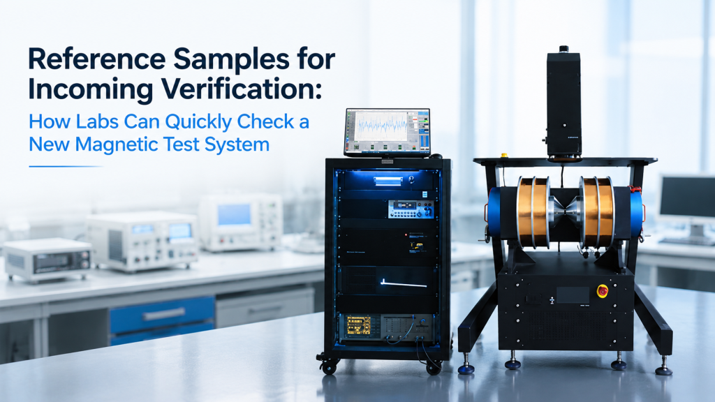
A new magnetic test system has arrived.
The crates are open. The cables are connected. The software starts normally. The magnet produces a field, and the measurement screen shows numbers.
But one important question remains:
How can the laboratory quickly confirm that the system is producing reasonable results before real research samples are tested?
This is where reference samples for magnetic test systems become useful.
A stable, well-characterized reference sample can help a laboratory perform an incoming verification check on a new:
- Hall measurement system
- vibrating sample magnetometer
- electromagnet
- Helmholtz coil system
- magnetic field calibration platform
- cryogenic magnetic measurement system
- sensor characterization system
- integrated Magnet & Field System
The purpose is not necessarily to repeat the manufacturer’s complete factory calibration.
The purpose is to answer practical questions:
- Is the system connected correctly?
- Is the field polarity correct?
- Are sample orientation and wiring correct?
- Are the measured values reasonably close to expectations?
- Is the result repeatable?
- Is there an obvious offset, noise, drift, or installation problem?
- Is the system ready for real samples?
This article explains how laboratories can select and use reference samples for fast incoming verification without confusing a quick functional check with formal calibration, metrological traceability, or full site acceptance.
1. What Incoming Verification Means
Incoming verification is a structured check performed after a new system is delivered and installed.
It may be completed:
- Before formal Site Acceptance Testing
- as part of Site Acceptance Testing
- before the first user training session
- after relocation
- after major maintenance
- after software or hardware changes
- before an important measurement campaign
Incoming verification should confirm that the delivered system operates consistently with the agreed configuration.
It may include:
- Visual inspection
- connection review
- safety checks
- software startup
- basic field output
- polarity confirmation
- reference-sample measurement
- repeatability check
- data export
- review of fault and status signals
It is broader than simply turning the equipment on.
2. Incoming Verification Is Not the Same as Calibration
These terms should not be mixed.
Functional Check
Confirms that the system starts, communicates, and performs basic operations.
Incoming Verification
Checks whether the installed system produces plausible and repeatable results under defined conditions.
Calibration
Establishes the relationship between an instrument’s indication and reference values, usually with stated uncertainty and traceability.
Validation
Confirms that the measurement method is suitable for its intended application.
Acceptance Testing
Determines whether the delivered system meets the agreed contractual specifications.
A reference sample can support all these activities, but the required sample, procedure, documentation, and uncertainty are different.
A five-minute reference-sample test does not automatically replace formal calibration or acceptance testing.
3. What Is a Reference Sample?
NIST defines a reference material as a sufficiently homogeneous and stable material that is fit for an intended use in a measurement process. Possible uses include calibration, assessment of a measurement procedure, assigning values to other materials, and quality control.
In practical laboratory language, a reference sample may be:
- A certified reference material
- a standard reference material
- a commercially calibrated sample
- a sample measured by an accredited laboratory
- a stable in-house control sample
- a previously characterized production sample
- a reference device with known response
- a durable sample reserved only for system checks
Not all reference samples provide the same level of confidence.
The laboratory should understand what the sample can prove—and what it cannot.
4. Certified Reference Material vs. In-House Check Sample
Certified Reference Material
A certified reference material has assigned property values supported by documentation, measurement uncertainty, and metrological traceability.
It may be suitable for:
- Instrument calibration
- method verification
- uncertainty evaluation
- external audits
- interlaboratory comparison
- formal quality systems
In-House Check Sample
An in-house check sample may not have certified values, but it can still be useful if it is stable and repeatedly measured under controlled conditions.
It may be suitable for:
- Daily system checks
- incoming verification
- detecting drift
- identifying sudden changes
- comparing results before and after maintenance
- operator training
- checking repeatability
NIST describes a check standard as a stable, well-characterized in-house standard that is remeasured periodically to determine whether the measurement process remains under statistical control.
The distinction is important:
A check sample can show that the system is behaving consistently. It does not automatically establish traceability or absolute accuracy.
5. One Sample Should Not Be Expected to Prove Everything
A single reference sample cannot verify every part of a magnetic test system.
For example, one VSM sample may help check:
- Magnetic moment scale
- field polarity
- loop shape
- coercivity repeatability
- sample mounting
But it may not fully verify:
- Maximum magnetic field
- low-moment sensitivity
- high-temperature operation
- cryogenic performance
- angular dependence
- background subtraction
- field uniformity
Similarly, one Hall sample may help check carrier type and approximate mobility, but may not verify every supported resistance, mobility, temperature, or magnetic field range.
A practical verification kit may need more than one reference item.
6. What Makes a Good Reference Sample?
A useful incoming-verification sample should be:
- Stable over time
- mechanically durable
- easy to mount
- clearly labeled
- resistant to contamination
- appropriate for the instrument’s measurement range
- sufficiently homogeneous
- supported by historical or certified values
- unlikely to change after normal handling
- similar to the laboratory’s real samples
NIST guidance on check standards emphasizes that an artifact used to monitor a measurement process should be close in material content and geometry to the items normally measured.
This is highly relevant to magnetic systems.
A reference sample that is completely different from the laboratory’s normal workload may confirm basic operation but provide limited information about real measurement performance.
7. Avoid Reference Samples Near the Instrument Limit
A reference sample should not normally sit too close to the system’s detection limit.
If the signal is barely above the noise floor, the laboratory may not know whether variation comes from:
- The instrument
- sample positioning
- environmental noise
- background subtraction
- the reference sample itself
Similarly, a sample should not force the system beyond its comfortable range.
Avoid samples that produce:
- Saturated electronics
- excessive induced voltage
- unstable contact heating
- mechanical overload
- magnetic moment beyond the calibrated range
- field requirements beyond the available magnet
A middle-range reference is usually more useful for initial verification.
8. Reference Samples for Hall Measurement Systems
For a Hall measurement system, a useful reference sample may be a stable semiconductor coupon or device with previously characterized:
- Carrier type
- sheet resistance
- carrier concentration
- Hall coefficient
- mobility
- thickness
- contact configuration
- temperature dependence
NIST describes Hall measurements as a method used to determine carrier density and mobility, normally through a combination of Hall and resistivity measurements.
A Hall reference sample can help identify:
- Reversed field polarity
- reversed sample-current polarity
- incorrect contact numbering
- wrong thickness entry
- unstable electrical contacts
- excessive voltage offset
- poor field reversal
- poor current reversal
- calculation or unit errors
9. Carrier Type Is a Fast Hall-System Check
One of the quickest checks is whether the system identifies the expected carrier type.
If a known n-type sample is reported as p-type, possible causes include:
- Magnetic field polarity is reversed.
- Current polarity is reversed.
- Hall voltage contacts are swapped.
- Contact numbering is incorrect.
- Sample orientation is wrong.
- Software sign conventions are inconsistent.
A correct carrier-type result does not prove full system accuracy.
But an incorrect sign is a strong indication that the setup should be reviewed before real samples are tested.
10. Use Known Ranges, Not Only One Perfect Number
A reference Hall sample may have an assigned or historical mobility value.
However, the incoming test should normally use an acceptable range rather than expect the measured value to match one number exactly.
Hall results can be affected by:
- Temperature
- magnetic field
- sample current
- contact resistance
- sample thickness
- contact geometry
- light exposure
- mounting stress
- calculation method
A practical incoming criterion may be:
- Correct carrier type
- sheet resistance within a defined range
- carrier concentration within a defined range
- mobility within a defined tolerance
- repeat measurements within a repeatability limit
This is more realistic than demanding exact equality with an old report.
11. Hall Contact Stability Must Be Verified
A reference sample is only useful if its contacts are stable.
Before interpreting the result, check:
- Contact I–V linearity
- contact resistance
- wire integrity
- probe pressure
- sample orientation
- contact numbering
- sample thickness entered in software
- sample temperature
- light conditions, when relevant
If one contact changes between measurements, the reference sample may create a false impression that the new instrument is unstable.
The reference fixture and wiring should be controlled as carefully as the sample.
12. A Hall Reference Sample Should Have a Dedicated Fixture
A reference sample that must be manually rewired every time adds unnecessary uncertainty.
A better setup may include:
- Dedicated sample holder
- fixed contact numbering
- keyed connector
- clear sample orientation
- strain relief
- stored software recipe
- recorded current and field settings
- protective storage box
The goal is to make the reference measurement repeatable between operators.
13. Hall Incoming Verification Sequence
A practical Hall-system incoming check may follow this sequence:
- Inspect the sample and contacts.
- Confirm sample thickness and geometry.
- Install the reference sample in its defined orientation.
- Check contact resistance or I–V behavior.
- Measure resistance at zero field.
- apply a positive magnetic field.
- measure Hall voltage.
- apply a negative magnetic field.
- repeat the measurement.
- calculate carrier type, concentration, and mobility.
- compare the results with the reference range.
- repeat the full sequence two or three times.
This sequence can quickly reveal wiring, polarity, contact, field, and repeatability problems.
14. Reference Samples for VSM Systems
A vibrating sample magnetometer measures magnetic moment by detecting the signal produced as a magnetized sample vibrates relative to pickup coils.
A suitable VSM reference sample may have characterized:
- Saturation magnetic moment
- specific magnetization
- coercivity
- remanence
- loop shape
- sample mass
- geometry
- orientation
- temperature condition
NIST maintains magnetic-moment Standard Reference Materials and supports metrology for magnetometers. NIST certificates for SRM 762 and SRM 772a state that these materials are intended for calibration of magnetometers, including vibrating sample magnetometers.
Where available and suitable for the instrument, such materials offer a stronger basis than an undocumented sample.
15. Why Sample Geometry Matters in VSM Verification
A VSM does not respond only to the material.
The result may also depend on:
- Sample shape
- sample dimensions
- position in the pickup coils
- vibration amplitude
- sample orientation
- holder background
- field direction
- demagnetizing effects
A reference sample should therefore be mounted using a controlled method.
If the sample is tilted, offset, or mounted at a different height, the measured moment may change even though the instrument is working correctly.
16. Mass and Units Must Be Checked
VSM results may be reported as:
- Magnetic moment
- magnetization
- specific magnetization
- volume magnetization
- mass-normalized magnetization
Before comparing results, confirm:
- Sample mass
- sample volume, if used
- unit system
- background subtraction
- density, if required
- data normalization setting
A simple unit or mass-entry error can make a correct measurement appear wrong by a large factor.
For incoming verification, compare the raw magnetic moment first whenever practical.
17. What a VSM Reference Sample Can Reveal
A stable VSM reference sample can help detect:
- Incorrect moment calibration
- wrong sample mass entry
- reversed field sign
- sample-position error
- excessive holder background
- poor centering
- abnormal loop noise
- excessive drift
- incomplete field sweep
- incorrect data normalization
- vibration problems
The loop shape can be as informative as the final numerical values.
Unexpected asymmetry, slope, offset, or noise may indicate a setup issue.
18. Use More Than One VSM Sample When Necessary
One strong ferromagnetic sample may verify the high-signal range but tell little about low-moment performance.
A broader verification kit may contain:
Medium- or High-Moment Reference
Useful for:
- Moment scale
- field polarity
- loop shape
- saturation behavior
Low-Moment Reference
Useful for:
- Sensitivity
- background subtraction
- sample-holder contribution
- noise
Low-Coercivity Reference
Useful for:
- Near-zero-field behavior
- field remanence
- field-step resolution
- loop centering
Hard-Magnetic Reference
Useful for:
- Wider field sweep
- coercivity
- remanence
- high-field operation
The laboratory does not need every type on the first day, but it should select references that reflect its real workload.
19. VSM Incoming Verification Sequence
A practical VSM check may include:
- Warm up the system according to the manual.
- run an empty-holder background measurement.
- inspect and weigh the reference sample.
- mount it at the defined position and orientation.
- center the sample using the agreed procedure.
- run a low- or medium-field loop.
- repeat the loop.
- compare moment, coercivity, remanence, and loop shape.
- remove and remount the sample.
- repeat the measurement.
- compare repeatability before and after remounting.
- export and archive the raw data.
This separates instrument repeatability from mounting repeatability.
20. Reference Devices for Magnetic Field Systems
A magnetic field system may not measure material properties directly.
It may generate a controlled field using:
- Electromagnet
- Helmholtz coil
- three-axis coil system
- bipolar power supply
- AC driver
- field controller
For incoming verification, the main reference may be a calibrated:
- Gaussmeter
- teslameter
- Hall probe
- fluxgate sensor
- scalar magnetometer
- three-axis magnetometer
The reference instrument should be suitable for:
- Required field range
- DC or AC operation
- field direction
- probe size
- expected accuracy
- sample-space geometry
21. Field-System Verification Should Begin at Zero
Before applying a large field, check the zero condition.
Record:
- Probe zero
- ambient magnetic field
- residual electromagnet field
- power-supply zero-current reading
- background field in each axis
- field after positive and negative operation
For an electromagnet, zero current does not always mean zero field because of remanence.
For a Helmholtz coil, environmental background field may be significant compared with a low test field.
A zero check provides context for later readings.
22. Verify Polarity Before Maximum Field
Apply a small positive setpoint and confirm the measured field direction.
Then apply a small negative setpoint.
This verifies:
- Coil wiring polarity
- power-supply polarity
- field-probe orientation
- software axis definition
- positive and negative command behavior
Polarity should be checked at a safe low field before testing maximum output.
This is especially important for three-axis systems.
23. Use Several Field Setpoints
A quick field-system verification should not rely on one maximum-field reading.
A practical set may include:
- Zero
- 10% of range
- 25% of range
- 50% of range
- 75% of range
- agreed maximum operating point
- corresponding negative values for bipolar systems
At each point, record:
- Current setpoint
- current readback
- measured field
- waiting time
- probe position
- magnet temperature
- cooling condition
This provides a basic field-current relationship and may expose saturation, current limiting, polarity, or scaling problems.
24. Repeatability Is Often More Useful Than One Perfect Reading
A single result can look good by chance.
Repeat the same field point several times.
A practical sequence may be:
- Set zero field.
- ramp to the test field.
- wait for stabilization.
- record the field.
- return to zero.
- repeat five times.
This checks:
- Field repeatability
- ramp behavior
- current-source repeatability
- magnet hysteresis
- probe positioning
- settling time
For an electromagnet, it may be necessary to approach the field from the same direction each time.
25. Use a Simple Spatial Check
A full 3D field map may not be necessary for the first incoming check.
However, the laboratory can verify several defined points:
- Center
- positive X offset
- negative X offset
- positive Y offset
- negative Y offset
- positive Z offset
- negative Z offset
The positions should correspond to the contracted uniformity region.
This does not replace a complete mapping report, but it can identify:
- Incorrect coil spacing
- misplaced probe
- unexpected asymmetry
- fixture interference
- wrong coordinate definition
- installation damage
26. Three-Axis Systems Need Axis-by-Axis Verification
For a three-axis Helmholtz coil, verify each axis separately.
X-Axis Test
- Command X field.
- confirm X response.
- check unwanted Y and Z components.
Y-Axis Test
- Command Y field.
- confirm Y response.
- check unwanted X and Z components.
Z-Axis Test
- Command Z field.
- confirm Z response.
- check unwanted X and Y components.
Then perform selected vector combinations.
This can reveal:
- Axis wiring errors
- swapped channels
- reversed polarity
- poor coordinate mapping
- axis cross-coupling
- sensor orientation errors
27. Incoming Verification for Cryogenic Magnetic Systems
A cryogenic magnetic system combines several measurement chains:
- Temperature
- magnetic field
- sample wiring
- heater control
- vacuum
- cooling
- data acquisition
A reference sample may behave differently at room temperature and low temperature.
Incoming verification should therefore be staged.
Room-Temperature Stage
Check:
- Electrical continuity
- field polarity
- sample-holder wiring
- software operation
- reference-sample response
Cooldown Stage
Check:
- Temperature sensor response
- cooldown trend
- heater function
- thermal stability
- contact continuity
- reference-sample response at a defined temperature
Magnetic Stage
Check:
- Field at sample position
- field reversal
- temperature change during magnet operation
- reference-sample repeatability
Do not combine every test into one complex run before the individual subsystems have been checked.
28. A Reference Sample Cannot Separate Every Error Automatically
Suppose a Hall reference sample gives an unexpected mobility.
Possible causes include:
- Field error
- current error
- voltage error
- contact problem
- wrong thickness
- wrong temperature
- sample damage
- software calculation
- incorrect reference value
The sample alone does not identify the cause.
It tells the laboratory that the full measurement chain needs investigation.
Reference samples are diagnostic tools, not automatic explanations.
29. Store the Original Incoming Baseline
The first successful incoming-verification results are valuable.
Save:
- Raw data
- processed results
- sample photographs
- fixture configuration
- sample mass and dimensions
- software version
- instrument settings
- environmental conditions
- probe position
- test date
- operator
- acceptance limits
This becomes the laboratory’s baseline for future comparisons.
If the system behaves differently six months later, the incoming baseline can help identify when performance changed.
30. Use a Control Chart for Long-Term Monitoring
A reference sample becomes more useful when measured periodically.
The laboratory can track:
- Mean result
- repeatability
- offset
- drift
- noise
- coercivity
- magnetic moment
- carrier concentration
- mobility
- field output
NIST guidance recommends measuring an appropriate check standard periodically and plotting the results on control charts. Values outside warning or control limits may indicate changes in bias, precision, or measurement-process control.
The laboratory does not need to build a complex quality system on the first day.
A simple trend chart is already better than relying on memory.
31. Establish Limits from Data, Not Guesswork
A reference-sample limit should be based on:
- Certified uncertainty
- supplier acceptance criteria
- historical measurements
- method repeatability
- remounting variation
- environmental variation
- application requirements
Avoid choosing limits only because a round number looks convenient.
For example:
“Result must be within 1%” may be unrealistic if mounting alone creates 2% variation.
Conversely, “within 20%” may be too loose to detect a serious problem.
Collect baseline data and set limits that reflect the real process.
32. Use Different Samples for Calibration and Independent Verification
A sample used to create the instrument calibration should not always be treated as an independent validation sample.
NIST’s reference-material definition notes that a single reference material cannot be used for both calibration and validation of results in the same measurement procedure.
A practical system may therefore use:
- Calibration standard A
- independent verification sample B
- routine check sample C
Not every laboratory needs all three immediately.
But the roles should be understood.
33. Protect the Reference Sample
A reference sample should not be treated like an ordinary sample.
Protect it from:
- Scratching
- corrosion
- oxidation
- contamination
- moisture
- bending
- broken contacts
- accidental heating
- excessive magnetic field
- mechanical shock
- uncontrolled cleaning
- repeated handling
Store it in a labeled container with:
- Sample ID
- orientation
- mass
- dimensions
- contact map
- expected values
- allowed conditions
- measurement procedure
If the sample changes, the reference history loses value.
34. Record Orientation and Magnetic History
Some magnetic materials depend on orientation and field history.
The reference procedure may need to state:
- Measurement axis
- sample face direction
- initial magnetization state
- demagnetization procedure
- maximum applied field
- sweep direction
- number of conditioning loops
- temperature history
A hard magnet measured in a different direction may give a very different loop.
A low-coercivity sample may also respond to residual field or handling.
Reference-sample orientation should never rely only on memory.
35. Reference Sample Stability Should Be Checked
A reference sample is useful only if it remains stable.
Possible changes include:
- Oxidation
- moisture absorption
- contact aging
- adhesive degradation
- mechanical cracking
- magnetic aging
- contamination
- mass loss
- thermal cycling damage
- demagnetization
If a reference result changes suddenly, do not assume the instrument is at fault.
Inspect the sample and compare it with another check item when possible.
36. Do Not Use a Valuable Research Sample as the Only Reference
A unique research sample may be poorly suited for routine verification because:
- Its true value may be uncertain.
- It may degrade.
- It may be difficult to remount.
- It may be irreplaceable.
- Its response may depend strongly on history.
- Different users may handle it differently.
A reference sample should ideally be replaceable or supported by sufficient documentation and backup data.
37. Incoming Verification Should Match the Purchased Scope
The verification plan should be based on the agreed system specifications.
For a Hall system, that may include:
- Carrier concentration
- mobility
- sheet resistance
- field range
- temperature range
For a VSM, that may include:
- Moment range
- field range
- sensitivity
- loop repeatability
- sample positioning
For a magnetic field system, that may include:
- Maximum field
- uniformity volume
- stability
- polarity
- control interface
- cooling
Do not reject a system for failing a test that was never part of the agreed configuration.
Likewise, do not accept a system only because it passes an easy reference test if major contracted requirements remain unverified.
38. Use Reference Samples Alongside Instrument Checks
A complete incoming check may use several types of reference.
Electrical Reference
- Precision resistor
- dummy load
- shorted input
- known voltage source
Magnetic Field Reference
- Calibrated gaussmeter
- reference magnetometer
- calibrated field probe
Material Reference
- Hall reference sample
- magnetic-moment standard
- stable in-house magnetic sample
Mechanical Reference
- Gauge block
- sample-position fixture
- alignment target
- calibrated spacer
The most efficient verification plan checks each subsystem separately before evaluating the full integrated measurement.
39. What to Ask the Supplier Before Shipment
Buyers should discuss incoming verification before the system leaves the factory.
Ask:
- Is a reference sample included?
- What properties have been assigned?
- Is the sample certified or an in-house check sample?
- What data was obtained during FAT?
- Is the exact sample ID recorded?
- Is a fixture included?
- What test settings should be used?
- What acceptance range is recommended?
- Is raw FAT data available?
- Can the supplier demonstrate the procedure remotely?
- Can replacement reference samples be purchased?
- What environmental conditions apply?
This avoids uncertainty after delivery.
40. What a Reference-Sample Certificate Should Contain
A useful reference document may include:
- Sample identification
- material description
- dimensions
- mass
- orientation
- assigned or historical values
- uncertainty, if applicable
- measurement temperature
- magnetic field range
- measurement method
- date
- laboratory
- storage instructions
- limitations
- validity or recheck recommendation
NIST Standard Reference Materials are supplied with documentation containing assigned values, stated uncertainties, and information concerning use and stability.
An ordinary in-house sample may have less documentation, but the laboratory should still record enough information to reproduce the check.
41. A Practical Incoming Verification Plan
A simple plan can be divided into five stages.
Stage 1: Documentation Review
Confirm:
- Model and serial numbers
- delivered configuration
- software version
- calibration documents
- FAT report
- wiring diagrams
- reference-sample data
- acceptance criteria
Stage 2: Installation Check
Confirm:
- Power
- grounding
- cooling
- communication
- sample holder
- probe position
- safety interlocks
- cable routing
Stage 3: Blank and Zero Checks
Measure:
- Electrical zero
- empty-holder background
- ambient field
- residual field
- noise
- drift
Stage 4: Reference Measurement
Measure the selected reference sample according to the agreed procedure.
Stage 5: Repeatability and Documentation
Repeat the test, compare results with limits, archive the data, and document any deviations.
42. When a Result Is Outside the Expected Range
Do not immediately conclude that the equipment is defective.
Review the problem systematically.
Check the Sample
- Damage
- contamination
- orientation
- mass
- thickness
- contacts
- storage history
Check the Fixture
- Position
- centering
- contact pressure
- orientation
- magnetic materials
- cable strain
Check the Instrument Settings
- Units
- field range
- current
- temperature
- averaging
- background subtraction
- calibration file
- sample geometry
Check the Environment
- Nearby magnets
- vibration
- temperature
- grounding
- electrical noise
- light exposure
- cable movement
Check Repeatability
Repeat the measurement without remounting, and then repeat after remounting.
This helps separate instrument, fixture, and sample effects.
43. When to Contact the Supplier
Contact the supplier when:
- The system cannot reach an agreed field.
- Polarity or axis behavior is inconsistent.
- Safety interlocks do not operate correctly.
- Reference results remain outside limits after setup checks.
- Repeatability is poor.
- Software calculation appears inconsistent.
- Noise is significantly higher than FAT data.
- The system shows fault codes.
- Cooling or temperature behavior is abnormal.
- Delivered documentation does not match the hardware.
Provide:
- Photos
- raw data
- test settings
- sample ID
- software version
- fault logs
- screenshots
- measured environmental conditions
- a description of troubleshooting already completed
Good evidence makes remote support much more efficient.
44. Common Buyer Mistakes
Mistake 1: Using an Unknown Sample
A sample with no reliable history cannot provide a meaningful expected result.
Mistake 2: Expecting Exact Agreement
Reference measurements should consider uncertainty, repeatability, temperature, mounting, and method differences.
Mistake 3: Ignoring Sample Orientation
Magnetic and electrical results may depend strongly on orientation.
Mistake 4: Using the Wrong Units
Moment, magnetization, carrier density, and mobility can be reported in different unit systems.
Mistake 5: Skipping Blank Measurements
Empty-holder, zero-field, and background measurements help identify system offsets.
Mistake 6: Testing Only Once
Repeatability is more informative than one isolated result.
Mistake 7: Confusing Verification with Calibration
A quick sample check cannot automatically establish traceability or full measurement uncertainty.
Mistake 8: Failing to Save Incoming Data
Without an initial baseline, future drift is harder to diagnose.
45. How Cryomagtech Supports Incoming Verification
Cryomagtech supplies Hall measurement systems, VSM-related magnetic characterization equipment, electromagnets, Helmholtz coils, excitation power supplies, field sensors, cryogenic instruments, and custom Magnet & Field Systems.
For incoming verification and system acceptance projects, we help evaluate:
- Suitable Hall or magnetic reference samples
- field-probe selection
- empty-holder and background checks
- field polarity and axis verification
- sample mounting and orientation
- reference measurement procedures
- FAT reference data
- repeatability criteria
- field-current verification
- multi-point field checks
- control and data-export functions
- remote startup guidance
- acceptance boundaries
- long-term check-sample planning
A new system should not be judged only by whether it powers on.
A useful incoming-verification process should show that the complete measurement chain—from field generation and sample mounting to signal acquisition and calculation—produces stable and reasonable results.
References
- NIST – SRM Definitions
https://www.nist.gov/srm/srm-definitions - NIST – Hall Effect Measurements Introduction
https://www.nist.gov/pml/nanoscale-device-characterization-division/popular-links/hall-effect/hall-effect-measurements-3 - NIST – Certificate of Analysis for SRM 772a
https://tsapps.nist.gov/srmext/certificates/772A.pdf - NIST – Magnetic Materials Metrology
https://www.nist.gov/programs-projects/magnetic-materials-metrology - NIST – What Is a Check Standard?
https://www.itl.nist.gov/div898/handbook/mpc/section1/mpc12.htm - NIST – Control Charts for Check Standards
https://www.nist.gov/system/files/documents/2019/05/14/sop-17-control-charts-check-standards-20190508.pdf
Key Takeaways
- Reference samples for magnetic test systems help laboratories verify a new system after delivery.
- Incoming verification is not automatically the same as calibration, validation, or contractual acceptance.
- Certified reference materials can support calibration and traceability, while stable in-house check samples are useful for repeatability and long-term monitoring.
- Hall reference samples can reveal polarity, wiring, contact, thickness, and calculation errors.
- VSM reference samples can help verify magnetic moment, loop shape, field sign, background subtraction, and sample positioning.
- Magnetic field systems should be checked with a suitable calibrated field probe at zero, positive, negative, and multiple intermediate setpoints.
- Reference samples should be stable, well documented, properly stored, and representative of the laboratory’s normal workload.
- Results should be compared with defined acceptance ranges rather than one exact number.
- The original incoming data should be saved as a baseline for future troubleshooting and control charts.
- A reference sample identifies that the measurement chain may have a problem; it does not automatically identify the exact cause.
For incoming verification, the key question is not only:
“Does the new magnetic test system turn on?”
The better question is:
“Can it measure a stable reference under controlled conditions and reproduce the result when the test is repeated?”