
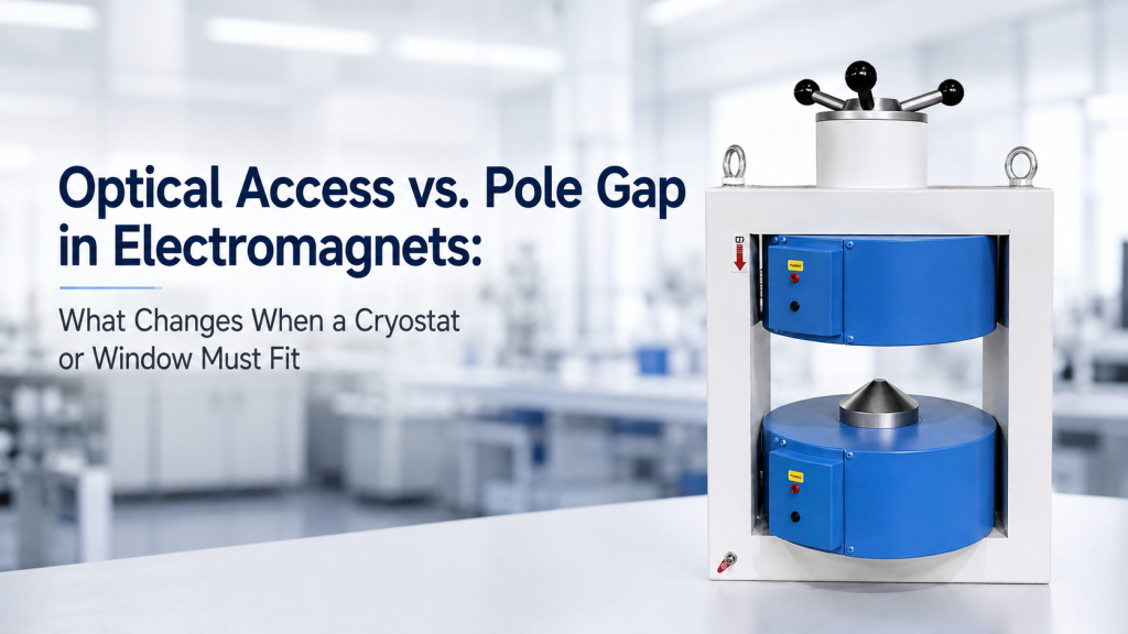
In many magnetic experiments, the first question is:
“How strong can the electromagnet be?”
That is important.
But when the experiment also needs optical access, cryostat integration, camera access, laser alignment, or a sample window, the better question is:
“What field can the electromagnet still deliver after the required physical access is included?”
Optical access and pole gap are not small mechanical details. They directly affect magnetic field level, field uniformity, working distance, pole design, sample position, power supply requirements, cooling, and system cost.
This is especially important for:
- Magneto-optical measurements
- MOKE experiments
- Photoluminescence under magnetic field
- Optical cryostat integration
- Low-temperature Hall or transport measurements with windows
- Microscopy inside a magnetic field
- Laser reflection or transmission measurements
- Custom electromagnet systems for material research
This article explains what changes when a cryostat, window, optical path, or working-distance requirement must fit inside an electromagnet.
1. Pole Gap Is One of the Most Expensive Parameters
The pole gap is the distance between the electromagnet pole faces.
For a simple electromagnet, reducing the gap usually makes it easier to generate a stronger magnetic field. Increasing the gap usually makes the magnet harder to drive.
A teaching document from the U.S. Particle Accelerator School gives a simplified relationship for a dipole-type magnet where the magnetic field is related to coil current and gap height, showing why gap size is a core design variable in magnet performance.
This does not mean every electromagnet follows one simple formula exactly.
Real magnets also depend on:
- Pole material
- yoke geometry
- coil turns
- current
- cooling
- saturation
- pole diameter
- fringe field
- sample position
- duty cycle
- field uniformity requirement
But the engineering direction is clear:
A larger pole gap usually requires more magnetic design effort to reach the same field.
2. Optical Access Forces the Gap to Become Larger
In a simple magnetic test, the sample may be small and placed directly between the pole faces.
But optical experiments require more space.
Optical access may need room for:
- Cryostat body
- vacuum jacket
- optical windows
- laser beam path
- camera path
- objective lens
- microscope working distance
- sample holder
- electrical wiring
- temperature sensor wires
- cooling lines
- mechanical alignment adjustment
A sample that is only 10 mm wide may require a much larger pole gap once the real optical and cryogenic hardware is included.
This is where many projects become unrealistic.
The buyer may request high field and large access at the same time, without realizing that both requirements compete with each other.
3. Cryostat Outer Diameter Is Not the Same as Required Pole Gap
A common mistake is to say:
“The cryostat diameter is 50 mm, so the pole gap should be 50 mm.”
That is usually not enough.
The real pole gap may need to include:
- Cryostat outer diameter
- window protrusion
- flange or collar
- sample holder offset
- cable exit space
- mechanical tolerance
- alignment margin
- vibration clearance
- thermal contraction allowance
- safety clearance
- field probe access
If the cryostat is 50 mm wide, the required working gap may be 60 mm, 70 mm, or more depending on the layout.
The magnet must be designed around the real working envelope, not only the cryostat catalog diameter.
4. Optical Windows Add Both Space and Optical Constraints
Optical windows are not just holes in the cryostat.
They affect:
- Beam path
- wavelength transmission
- working distance
- window angle
- window thickness
- optical distortion
- reflection
- polarization effects
- thermal radiation
- mechanical protrusion
- available pole gap
Lake Shore notes that standard optical cryostats often use fused silica windows and that different window materials may be selected for different wavelength ranges, from x-rays to THz applications.
For magnet integration, the key point is practical:
Window material, window size, and window location must be checked before the electromagnet pole gap is finalized.
5. Working Distance Can Be More Important Than Window Size
In optical experiments, the window may fit physically, but the optical system may still fail.
Why?
Because the lens or objective may need a certain working distance.
Working distance is the space required between the optical component and the sample or window.
If the electromagnet pole, cryostat wall, or yoke blocks the lens, the optical system may not focus correctly.
Buyers Should Confirm
- Required objective working distance
- laser incidence angle
- camera viewing direction
- window-to-sample distance
- pole face-to-sample distance
- space for lens mount
- space for optical alignment
- whether the beam is normal, oblique, reflected, or transmitted
A magnet that fits the cryostat may still fail the optical experiment if the working distance is not enough.
6. Reflection Geometry and Transmission Geometry Need Different Space
Optical access depends on measurement geometry.
Reflection Geometry
In reflection geometry, light enters and returns from the same side.
This may be used for:
- MOKE
- reflectivity
- microscopy
- surface optical measurements
- some photoluminescence setups
Reflection geometry may require:
- front-side window
- lens access
- collection path
- beam splitter or camera path
- stable sample angle
- clear space on one side of the magnet
Transmission Geometry
In transmission geometry, light passes through the sample.
This may be used for:
- absorption
- transmission spectroscopy
- some photoluminescence and optical characterization
- transparent or thin samples
Transmission geometry may require:
- aligned entrance and exit windows
- clear path through both pole regions
- sample centered in the optical path
- enough space behind the cryostat
- no obstruction from yoke or pole supports
A magnet designed for reflection may not automatically support transmission.
The optical path must be defined in the RFQ.
7. Beam Angle Changes the Mechanical Design
Not all optical access is straight.
Some experiments require:
- normal incidence
- oblique incidence
- grazing incidence
- collection at an angle
- polarization control
- side window access
- top window access
- multi-window access
An oblique beam may need more lateral clearance than a straight beam.
A cryostat window may be physically visible but still unusable if the pole piece blocks the actual beam angle.
For MOKE and magneto-optical experiments, field direction, optical incidence angle, and sample plane must be considered together.
8. Pole Diameter Also Matters
Buyers often focus on pole gap, but pole diameter is also important.
Pole diameter affects:
- Field uniformity
- usable sample area
- fringe field
- optical blockage
- mechanical clearance
- field strength
- access to the sample
- cryostat integration
A larger pole diameter may improve uniformity over a larger region, but it may block optical access or reduce available working space.
A smaller pole may improve access but may reduce the usable uniform field region.
There is no universal best pole size.
It depends on sample size, field uniformity requirement, optical path, and cryostat geometry.
9. Larger Gap Usually Means More Power and More Cooling
When the pole gap increases, the magnet may need more current or more ampere-turns to reach the same field.
This can lead to:
- Larger coil
- higher current
- higher voltage
- larger power supply
- more heat
- water cooling
- larger yoke
- higher system weight
- stronger support frame
- higher cost
This is why optical access should not be treated as a free modification.
A larger gap may look like a mechanical request, but it changes the electromagnetic and thermal design.
10. Field Uniformity Can Change When the Gap Changes
Pole gap affects not only maximum field.
It also affects field distribution.
The usable uniform region depends on:
- Pole diameter
- pole gap
- pole shape
- sample position
- yoke design
- fringe field
- field level
- magnetic saturation
If the gap is enlarged to fit a cryostat, the field uniformity at the sample may change.
A field value measured at the center point is not enough if the sample, optical spot, or device occupies a larger region.
Better Specification
Instead of saying:
“1 T field with optical access”
say:
“1 T at the sample position with a 70 mm pole gap, and uniformity within ±X% over a defined sample region.”
This is measurable and much safer.
11. Sample Position Must Be Known Inside the Cryostat
In a cryostat, the sample is not always at the geometric center of the outer body.
The sample may be offset by:
- Cold finger geometry
- sample holder design
- window position
- thermal shield
- wiring path
- insert structure
- mounting flange
- rotation stage
- optical stage
For magnet design, the most important point is the sample position.
The electromagnet must place the field center at the sample, not merely around the cryostat body.
Buyers Should Provide
- Cryostat drawing
- sample center height
- distance from window to sample
- outer diameter at magnet insertion region
- window location
- field direction relative to sample
- optical path direction
- cable exit and cooling line direction
Without this, the magnet supplier can only guess.
12. Optical Access Can Conflict with Field Direction
Different experiments need different field directions.
For example:
- Longitudinal MOKE may require in-plane magnetic field.
- Polar MOKE may require out-of-plane magnetic field.
- Hall measurements may require field perpendicular to the sample plane.
- Magnetoresistance may require field parallel or perpendicular to current.
- Optical cryostat experiments may require field along or across the optical path.
The magnet must be designed so that the field direction, sample plane, and optical path are compatible.
A magnet that provides the correct field strength may still be wrong if the field direction blocks the required optical geometry.
13. Pole Piece Shape May Need Customization
Standard flat pole pieces are not always ideal for optical access.
Depending on the experiment, custom pole pieces may be considered.
Possible Pole Piece Options
- Flat poles
- tapered poles
- bored poles
- optical-access poles
- extended pole tips
- removable pole pieces
- larger-diameter poles
- smaller-diameter poles
- special geometry for cryostat clearance
Each choice has trade-offs.
A bored or modified pole may improve optical access but can affect field strength or uniformity.
A tapered pole may improve clearance but reduce usable field region.
A custom pole design should be evaluated together with the required field performance.
14. Cryostat Integration May Require a Non-Standard Magnet Frame
Sometimes the issue is not only pole gap.
The magnet frame itself may need to change.
A cryostat may require:
- vertical insertion
- side access
- top loading
- optical table mounting
- low-profile base
- larger clearance around windows
- removable front section
- adjustable height
- special support frame
- vibration isolation
A standard electromagnet may not provide enough physical access.
In this case, a custom magnet frame may be more important than simply increasing the pole gap.
15. Vibration and Mechanical Stability Matter for Optical Work
Optical experiments are often sensitive to vibration.
Possible vibration sources include:
- water cooling flow
- cooling fans
- cryocooler vibration
- pump lines
- unstable optical table
- loose magnet frame
- cable pull
- mechanical stage movement
- floor vibration
A magnet that is acceptable for electrical measurements may not be stable enough for high-magnification optical measurements.
For optical cryostat integration, mechanical stability should be part of the system discussion.
16. Thermal Constraints Can Change Optical Alignment
Cryogenic systems move.
During cooldown, thermal contraction can shift:
- sample position
- window position
- optical focus
- cable tension
- stage alignment
- holder position
- thermal shield clearance
Even if the system aligns at room temperature, the optical path may shift at low temperature.
This matters for:
- MOKE
- micro-photoluminescence
- microscope-based measurements
- small samples
- narrow laser spots
- long-duration optical measurements
Buyers should clarify whether alignment must be maintained during cooldown or adjusted after reaching target temperature.
17. Field Probe Access Should Not Be Forgotten
If the system needs field verification, a field probe must reach the sample region.
But optical and cryostat hardware may block field probe access.
A complete design should consider:
- Where the field probe can be inserted
- whether the probe can reach the sample position
- whether the probe fits inside the gap
- whether probe access conflicts with optical access
- whether field verification is done before cryostat installation
- whether field is measured directly or inferred from current
For formal acceptance, field verification should be practical.
Do not design a system where the field requirement cannot be measured.
18. Cable and Cooling Line Routing Can Decide the Real Gap
Even if the cryostat body fits, the system may fail when cables and cooling lines are connected.
Check:
- Sample wires
- heater wires
- temperature sensor leads
- camera cables
- optical fiber
- vacuum hose
- cryogen line
- compressor line
- water cooling hose
- power cables
- field probe cable
These components need bend radius and strain relief.
A cable exiting toward the pole face may require more gap than the cryostat body itself.
This is why layout drawings matter.
19. Optical Access vs. Magnetic Field: Common Trade-Offs
Here is the practical trade-off list.
If You Increase Pole Gap
You may gain:
- More cryostat clearance
- easier window access
- better lens access
- more sample holder space
- easier cable routing
But you may lose:
- maximum field
- field efficiency
- compact size
- lower power consumption
- lower cost
- easier cooling
If You Keep Pole Gap Small
You may gain:
- stronger field
- better magnetic efficiency
- smaller magnet
- lower power requirement
- lower cost
But you may lose:
- optical access
- cryostat compatibility
- working distance
- sample loading space
- field probe access
- cable clearance
The correct answer depends on which performance matters most.
20. What Buyers Should Confirm Before Requesting a Quote
Before requesting an electromagnet for optical or cryogenic use, buyers should prepare the following information.
Cryostat Information
- Manufacturer and model
- outer diameter at magnet gap
- sample center position
- window size and location
- window material
- cryostat mounting direction
- cable exit location
- cooling line location
- required working clearance
Optical Information
- Reflection or transmission geometry
- laser wavelength
- beam diameter
- incidence angle
- collection angle
- camera or detector access
- objective working distance
- required optical aperture
- polarization sensitivity
- microscope or lens size
Magnetic Information
- Required field strength
- field direction
- pole gap
- pole diameter
- uniformity requirement
- sample volume
- DC, sweep, or AC operation
- duty cycle
- cooling method
- field verification method
Mechanical Information
- Optical table or floor mounting
- magnet height
- cryostat support
- vibration sensitivity
- sample exchange workflow
- alignment adjustment
- space limits
- lifting or installation constraints
These details allow the supplier to design the system around the real experiment.
21. Common Buyer Mistakes
Mistake 1: Asking for High Field and Large Gap Without Trade-Off Awareness
High field and large optical clearance can be achieved only within practical design limits.
Mistake 2: Providing Cryostat Diameter Only
The supplier needs sample position, window location, cable exits, and working clearance.
Mistake 3: Forgetting Working Distance
A window may fit, but the lens or objective may not.
Mistake 4: Not Defining Optical Geometry
Reflection, transmission, oblique incidence, and side-view imaging require different space.
Mistake 5: Ignoring Field Uniformity
A larger gap can change usable field uniformity.
Mistake 6: Treating Field Probe Access as Optional
If the field must be accepted, the field must be measurable.
Mistake 7: Not Defining Responsibility Boundaries
The magnet supplier, cryostat supplier, optical table team, and end user must know who handles integration.
22. Better RFQ Example
Weak RFQ
“We need an electromagnet with 1 T field and optical access for a cryostat.”
This is not enough.
Better RFQ
“We need a horizontal-field electromagnet for optical cryostat integration. The cryostat outer diameter at the magnet gap is 60 mm, and the sample center is 35 mm from the outer window surface. The optical path is reflection geometry from the front side, with a 20 mm beam clearance and 80 mm objective working distance. Required field is 0.8 T at the sample position with a 70 mm pole gap under DC operation. Please evaluate pole diameter, field uniformity over a 10 mm sample region, cooling method, power supply requirement, and field verification method.”
This is much easier to evaluate.
It gives the supplier the real design problem.
23. How Cryomagtech Supports Optical-Access Electromagnet Projects
Cryomagtech supplies electromagnets, magnetic field power supplies, Helmholtz coils, cryogenic instruments, field sensors, and custom Magnet & Field Systems for optical, low-temperature, Hall, MOKE, and material research applications.
For optical-access electromagnet projects, we help evaluate:
- Required pole gap
- cryostat clearance
- sample center position
- window location and optical path
- reflection or transmission geometry
- pole diameter and field uniformity
- field strength trade-offs
- working distance
- power supply and cooling requirements
- cable and cooling line routing
- field probe access
- custom pole or frame options
- integration responsibility boundaries
A good optical-access electromagnet is not simply a standard magnet with a bigger gap.
It is a magnetic, optical, thermal, and mechanical integration problem.
References
- U.S. Particle Accelerator School – Electromagnets and Magnet Design
https://uspas.fnal.gov/materials/12MSU/magnet_elements.pdf - Lake Shore Cryotronics – Cryostat Windows
https://www.lakeshore.com/products/product-detail/janis/cryostat-windows - Wikipedia – Electromagnet
https://en.wikipedia.org/wiki/Electromagnet - Wikipedia – Faraday Effect
https://en.wikipedia.org/wiki/Faraday_effect
Key Takeaways
- Optical access and pole gap are directly connected in electromagnet design.
- A larger pole gap may be required for a cryostat, optical window, lens, working distance, cable exit, or field probe.
- Increasing pole gap usually reduces magnetic efficiency and may require a larger magnet, stronger power supply, and better cooling.
- Cryostat outer diameter alone is not enough; sample position, window location, optical path, and cable routing must also be defined.
- Reflection and transmission geometries require different mechanical access.
- Pole diameter, pole shape, and frame design may need customization for optical experiments.
- Working distance can decide whether an optical setup is usable, even when the cryostat physically fits.
- Field verification access should be considered before the magnet is built.
For optical-access electromagnet projects, the key question is not only:
“Can the cryostat fit between the poles?”
The better question is:
“Can the cryostat, optical path, working distance, sample position, field level, and pole gap work together under real experimental conditions?”