
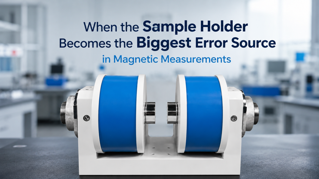
In magnetic measurement projects, buyers often focus on the main equipment:
- Helmholtz coil
- Electromagnet
- Hall measurement system
- Power supply
- Field probe
- Software
- Temperature controller
These are all important.
But in many real experiments, the biggest error source is not the magnet, the coil, or the power supply.
It is the sample holder.
A poorly designed sample holder can shift the sample away from the field center, introduce magnetic background, create contact problems, add thermal drift, block optical access, distort low-field measurements, or make repeated measurements inconsistent.
This article explains how the sample holder becomes a hidden error source in magnetic measurements—and how buyers can reduce that risk before purchasing or designing a magnetic field system.
1. Why Sample Holders Are Often Underestimated
A sample holder looks like a simple accessory.
It may be a small plate, clamp, rod, cartridge, probe fixture, chip carrier, slide mount, or custom bracket. Because it looks simple, many users leave it until the end of the project.
That is a mistake.
The sample holder controls:
- Sample position
- Sample orientation
- Contact stability
- Thermal path
- Optical access
- Mechanical repeatability
- Cable routing
- Background magnetic signal
- Distance from field center
- Alignment with the magnetic field direction
Quantum Design’s sample mounting guidance for magnetometry states clearly that the sample holder can be a major contributor to background signal, and that this can be reduced by choosing low-susceptibility materials and keeping holder mass low.
For magnetic measurements, the holder is not just a piece of hardware.
It is part of the measurement system.
2. The First Error: Magnetic Background from the Holder
The most obvious risk is magnetic contamination.
A sample holder may contain:
- Steel screws
- magnetic stainless steel
- springs
- clips
- pins
- washers
- solder
- adhesive residue
- plated connectors
- magnetic coatings
- motorized parts nearby
In high-field measurements, these materials may experience force or torque.
In low-field measurements, they may distort the local magnetic environment.
In magnetometry, they may contribute background signal that is comparable to or larger than the sample signal.
Practical Problem
A user may think they are measuring a thin film, powder, small crystal, or sensor response.
But part of the signal may come from the holder, screws, glue, tape, or mounting plate.
That is not a magnet problem.
That is a sample-holder problem.
3. Non-Magnetic Does Not Always Mean Magnetically Invisible
Many buyers say:
“We will use a non-magnetic holder.”
Good. But that statement is not detailed enough.
Different materials may still have different magnetic behavior.
Common fixture materials include:
- Aluminum
- Brass
- Copper
- Titanium
- PEEK
- PTFE
- Quartz
- Glass
- Ceramic
- G10 / FR4
- Austenitic stainless steel
- 3D-printed polymers
Some are better for certain applications than others.
Important Reminder
“Non-magnetic” is not the same as:
- zero background
- low susceptibility
- low thermal expansion
- low outgassing
- good electrical insulation
- good mechanical rigidity
- suitable for cryogenic use
- compatible with vacuum
- compatible with optical access
Material selection should match the experiment, not just the label.
4. Position Error: When the Sample Is Not Where You Think It Is
Magnetic field specifications usually refer to a defined region:
- Field center
- uniform volume
- pole gap center
- coil center
- sample plane
- measurement axis
If the sample holder places the sample outside that region, the measurement may be wrong.
This is especially important in:
- Helmholtz coil systems
- electromagnets
- Hall measurement systems
- low-field calibration platforms
- MOKE setups
- cryostat-integrated experiments
- three-axis field systems
A Helmholtz coil is designed to create a relatively uniform magnetic field near the center, but the actual usable region depends on coil geometry and sample position.
If the holder shifts the sample away from the center, the field at the sample may no longer match the expected value.
5. Orientation Error: When the Sample Angle Is Wrong
In many experiments, sample orientation is as important as sample position.
This matters for:
- Hall measurements
- anisotropic materials
- thin films
- magnetoresistance
- MOKE
- sensor validation
- compass calibration
- angular field response testing
A small tilt or rotation error may change the measurement result.
Common Causes
Orientation errors may come from:
- Uneven clamp pressure
- loose holder
- rough mounting surface
- adhesive thickness
- sample not seated flat
- holder bending under load
- rotation stage backlash
- user remounting variation
- thermal contraction at low temperature
For angular magnetic measurements, the field may be correct, but the sample angle may not be.
That is enough to damage data quality.
6. Contact Problems in Hall Measurements
For Hall testing, the sample holder is also an electrical interface.
Poor contact design can create serious measurement errors.
NIST’s Hall effect measurement guidance lists practical error checks including whether probes or wires make good contact, whether contact I-V characteristics are linear, whether any contact has much higher resistance than others, whether voltages settle after current reversal, and whether sample temperature is uniform.
NIST also notes that in Hall and resistivity measurements, large offset voltage can come from nonsymmetric contact placement, sample shape, and nonuniform temperature.
For buyers, this means the holder is not secondary.
It directly affects the electrical measurement.
Hall Holder Risks
A poor Hall sample holder may cause:
- unstable contacts
- high contact resistance
- non-ohmic contact behavior
- contact asymmetry
- thermal voltage
- sample heating
- broken wire bonds
- wrong current path
- contact pressure variation
- poor repeatability after remounting
A better Hall system cannot fully fix bad contact geometry.
7. Mechanical Repeatability: The Hidden Requirement
Many users need to measure multiple samples or repeat the same measurement over time.
In that case, repeatable sample mounting matters.
A holder should help the user place the sample in the same position and orientation each time.
Repeatability Problems
Poor holders may cause:
- sample sliding
- inconsistent clamping
- different insertion depth
- angular variation
- cable pulling
- loose screws
- contact shift
- changed thermal contact
- changed optical alignment
If the measurement changes after remounting, the user may blame the magnet or instrument.
But the real cause may be fixture repeatability.
8. Holder Mass Can Matter in Sensitive Measurements
In magnetometry and low-signal experiments, the sample may be small.
If the holder is large, heavy, or magnetically active, its background may dominate.
Why Low Mass Helps
Lower holder mass can reduce:
- magnetic background
- thermal inertia
- mechanical loading
- vibration sensitivity
- cooldown time
- possible contamination
This does not mean the holder should be weak.
It means the holder should use only as much material as needed for stability and alignment.
For small samples, the holder should not become the largest object in the measurement volume unless the experiment requires it.
9. Thermal Effects: More Than Just Temperature
In cryogenic, variable-temperature, or heated measurements, the sample holder affects thermal behavior.
It can influence:
- sample temperature
- temperature gradient
- cooldown speed
- thermal stability
- contact heating
- heater response
- thermal EMF
- sample stress
- adhesive performance
A temperature sensor may read one location, while the sample is at another.
If the holder has poor thermal design, the reported temperature may not represent the actual sample temperature.
Common Thermal Mistakes
- Holder material has poor thermal conductivity
- sample is poorly thermally anchored
- wires bring heat into the sample area
- clamp pressure changes after cooling
- adhesive becomes brittle
- thermal expansion shifts alignment
- temperature sensor is too far from the sample
For low-temperature Hall and magnetic measurements, thermal design is not optional.
10. Cable Routing Can Turn the Holder into a Noise Source
Sample holders often carry wires.
These may include:
- Current leads
- voltage leads
- sensor output wires
- thermocouple wires
- heater wires
- optical detector cables
- field probe cables
Poor cable routing can create:
- pickup noise
- thermal EMF
- cable movement
- magnetic field disturbance
- ground loops
- unwanted mechanical torque
- vibration transfer
- contact strain
For low-field or weak-signal work, cables should be planned together with the holder.
A clean sample holder with messy cable routing is still a bad measurement interface.
11. Optical Access and Holder Shadowing
For MOKE, optical microscopy, photoluminescence, laser reflection, and camera-based experiments, the holder must not block the optical path.
A sample holder may create problems if it:
- blocks the laser beam
- blocks reflected light
- obstructs camera view
- interferes with microscope working distance
- causes unwanted reflections
- shifts the sample away from the focal plane
- blocks cryostat windows
- prevents sample rotation
For optical magnetic experiments, the holder must support both field geometry and optical geometry.
It is not enough for the sample to be inside the magnet.
It must be visible and correctly aligned.
12. Sample Holder and Field Uniformity
Field uniformity is usually specified over a certain volume.
If the holder is too large or places the sample outside the uniform zone, the user may lose the value of the coil design.
Example
A Helmholtz coil may provide good uniformity over a defined central region.
But if the holder places the sensor 30 mm above the center, or if a cable pulls the device sideways, the actual field at the sensor may be different.
For electromagnets, a holder may shift the sample closer to one pole face or away from the intended field center.
This can affect:
- field magnitude
- field direction
- gradient exposure
- measurement repeatability
- comparison between samples
Field uniformity is only useful if the sample actually stays inside the uniform region.
13. Sample Holder in Sensor Calibration
For sensor validation and calibration, the holder controls the relationship between the sensor coordinate system and the magnetic field coordinate system.
This is critical for:
- magnetometers
- compasses
- IMUs
- AHRS modules
- three-axis sensors
- navigation devices
A poor holder may introduce:
- axis misalignment
- tilt error
- rotation center error
- cable pull
- inconsistent orientation
- mechanical backlash
- non-repeatable mounting
NIST’s magnetic sensing and metrology program works on characterization and calibration of many magnetic sensors used in electronics, environmental monitoring, infrastructure, defense, and other applications. For this type of work, reliable measurement setup and calibration conditions are central to meaningful results.
For sensor calibration, the holder is not just a mount.
It defines the coordinate relationship.
14. Sample Holder in Electromagnet Systems
In electromagnets, holder design is strongly linked to pole gap and sample space.
The holder must fit between pole pieces while leaving room for:
- sample
- wires
- field probe
- optical access
- cryostat insert
- rotation or translation
- cooling clearance
- operator access
Electromagnet-Specific Risks
A holder may:
- require a larger pole gap
- reduce maximum field
- block field probe access
- contain magnetic parts
- shift sample away from pole center
- heat under high field or current
- experience mechanical force
- vibrate under changing field
For electromagnets, the sample holder should be considered before finalizing pole gap.
Do not design the magnet first and discover later that the sample fixture does not fit.
15. Sample Holder in Helmholtz Coil Systems
In Helmholtz coil systems, the holder should place the sample at the coil center and avoid disturbing the field.
Helmholtz-Specific Risks
A holder may:
- move the DUT outside the uniform region
- block the central test volume
- use magnetic screws
- introduce cable loops
- interfere with three-axis coil access
- create large thermal or mechanical mass
- reduce optical or hand access
- make sample rotation inaccurate
For three-axis Helmholtz systems, the holder should also support clear coordinate definition:
- X-axis field
- Y-axis field
- Z-axis field
- sensor orientation
- sample plane
- rotation reference
A three-axis field system with an unclear sample holder can produce confusing calibration results.
16. Sample Holder in Hall Measurement Systems
Hall measurement is especially sensitive to sample mounting and contact layout.
A good Hall sample holder should support:
- stable electrical contacts
- known sample geometry
- proper current path
- voltage contact positioning
- low thermal EMF
- minimal contact resistance imbalance
- repeatable mounting
- compatibility with magnetic field direction
- temperature control, if needed
A weak Hall signal can be easily buried under offset and contact-related errors.
In some cases, improving the sample holder and contact method may produce more benefit than upgrading the magnet.
That is not a glamorous answer, but it is often true.
17. What Buyers Should Define Before Ordering a Holder
Before asking for a magnetic measurement system, buyers should define the holder requirements clearly.
Sample Information
- Sample type
- sample size
- sample thickness
- sample shape
- fragile or rigid
- conductive or insulating
- powder, thin film, wafer, chip, bulk, or device
- temperature range
- optical access requirement
Magnetic Requirement
- Field direction relative to sample
- field strength
- uniformity region
- one-axis or three-axis field
- sample position
- field probe position
- rotation or translation requirement
Electrical Requirement
- Number of contacts
- current and voltage lead arrangement
- maximum current
- voltage signal level
- contact method
- cable type
- shielding and grounding
- current reversal requirement
Mechanical Requirement
- Mounting repeatability
- clamp method
- alignment reference
- sample exchange frequency
- non-magnetic material
- maximum holder size
- cryostat or vacuum compatibility
- optical path clearance
These details help the supplier design or recommend a holder that matches the measurement—not just a generic clamp.
18. Practical Design Guidelines
A good sample holder should usually follow these principles.
Use Appropriate Materials
Choose materials based on:
- magnetic background
- electrical insulation
- thermal behavior
- vacuum compatibility
- cryogenic compatibility
- mechanical stability
- optical requirements
Keep the Holder Simple
Avoid unnecessary mass, screws, brackets, and magnetic parts.
Define the Reference Point
Make it clear where the sample center is relative to:
- coil center
- pole center
- field probe position
- rotation axis
- optical axis
- cryostat center
Control Cable Routing
Plan wire exits, strain relief, shielding, and grounding.
Support Repeatability
Use alignment pins, reference surfaces, stops, or defined seating surfaces when repeatability matters.
Test the Holder Background
For sensitive magnetic measurements, measure the holder background without the sample.
This can reveal whether the holder itself is contributing too much signal.
19. When a Custom Holder Is Worth It
A custom holder adds cost and engineering time.
But it may be worth it when:
- the sample is small or fragile
- the signal is weak
- alignment matters
- low-temperature operation is required
- optical access is required
- repeatability matters
- multiple samples must be compared
- Hall contacts are difficult
- the sample must rotate
- the fixture must be non-magnetic
- publication-grade data is required
A generic holder is acceptable for simple tests.
But for serious magnetic measurements, the holder can decide whether the data is trustworthy.
20. How Cryomagtech Supports Sample Holder and Fixture Planning
Cryomagtech supplies Helmholtz coil systems, electromagnets, Hall measurement systems, magnetic field drivers, field sensors, and related fixtures for magnetic field testing and research applications.
For sample holder and fixture planning, we help evaluate:
- Sample size and position
- field direction and uniformity region
- pole gap or coil opening
- non-magnetic material selection
- Hall contact and wiring layout
- sensor coordinate alignment
- optical access clearance
- cryogenic or vacuum compatibility
- cable routing and strain relief
- repeatability and acceptance requirements
The sample holder should not be treated as a small accessory after the main system is chosen.
In many magnetic measurements, it is part of the measurement accuracy.
References
- Quantum Design – Sample Mounting Considerations
https://qdusa.com/siteDocs/appNotes/1014-201.pdf - NIST – Hall Effect Measurements: Sources of Error
https://www.nist.gov/pml/nanoscale-device-characterization-division/popular-links/hall-effect/resistivity-and-hall/hall - NIST – Resistivity and Hall Measurements
https://www.nist.gov/pml/nanoscale-device-characterization-division/popular-links/hall-effect/resistivity-and-hall - NIST – Magnetic Sensing and Metrology
https://www.nist.gov/programs-projects/magnetic-sensing-and-metrology
Key Takeaways
- The sample holder can become the biggest error source in magnetic measurements.
- Magnetic background from screws, clips, adhesives, and holder materials can distort low-signal data.
- Sample position and orientation must match the field center, uniform region, and measurement geometry.
- In Hall measurements, contact quality and contact symmetry can dominate the final result.
- Cable routing affects noise, thermal EMF, mechanical strain, and repeatability.
- For sensor calibration, the holder defines the relationship between the DUT coordinate system and the magnetic field coordinate system.
- Custom holders are worth considering when the sample is small, fragile, low-signal, cryogenic, optical, or alignment-sensitive.
For magnetic measurement systems, the key question is not only:
“Is the magnet accurate?”
The better question is:
“Is the sample held in a way that allows the magnet accuracy to actually matter?”