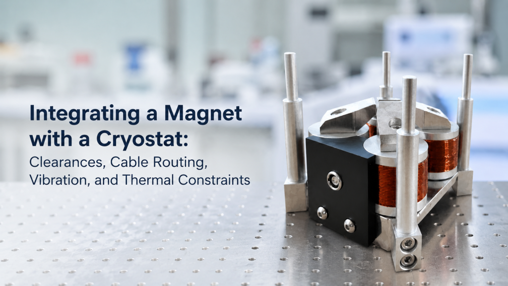
Integrating a magnet with a cryostat sounds simple at first.
The magnet provides the field.
The cryostat provides the low-temperature environment.
The sample sits somewhere in the middle.
In real laboratory systems, it is rarely that simple.
Many integration problems appear late because the buyer first discusses only magnetic field, temperature, and price. But the real success of a magnet–cryostat setup often depends on practical details: clearance, pole gap, sample position, cable routing, vibration, cooling lines, thermal load, optical windows, mechanical support, and installation boundaries.
This article explains what buyers should check before integrating an electromagnet, Helmholtz coil, magnetic field driver, or cryogenic instrument with a cryostat.
1. Why Magnet–Cryostat Integration Is Easy to Underestimate
A magnet and a cryostat may both work correctly as separate instruments.
The problem begins when they must work together.
A cryostat may require:
- Vertical sample access
- Vacuum space
- Cold finger clearance
- Optical windows
- Temperature sensors
- Heater wiring
- Sample leads
- Cooling lines
- Mechanical support
- Vibration isolation
A magnet may require:
- Pole gap
- Coil clearance
- Sample center alignment
- Water cooling or air cooling
- High-current cables
- Safety spacing
- Field probe access
- Non-magnetic fixtures
- Stable mechanical frame
When these requirements conflict, the system may be difficult to install even if each component meets its own specification.
For low-temperature Hall, optical, transport, MOKE, and magnetic material experiments, integration should be discussed before the system is quoted.
2. Start with the Real Sample Position
The most important reference point is not the outer size of the cryostat.
It is the real sample position.
Buyers should define:
- Where the sample is inside the cryostat
- Distance from cryostat outer wall to sample center
- Height of the sample above the mounting base
- Orientation of the sample plane
- Field direction required at the sample
- Optical path or electrical contact direction
- Space needed for sample holder and wiring
A magnet supplier cannot design the correct pole gap or coil opening if the actual sample position is unclear.
For example, a cryostat may physically fit between magnet poles, but the sample may not be located at the magnetic field center.
That is a serious problem.
3. Pole Gap and Cryostat Diameter Are Not the Same Requirement
For electromagnets, buyers often say:
“The cryostat outer diameter is 60 mm, so we need a 60 mm gap.”
That is usually not enough.
The required pole gap may also need to include:
- Mechanical tolerance
- thermal shield clearance
- window protrusion
- vacuum jacket shape
- cable exit space
- sample holder access
- alignment adjustment
- safety clearance
- future accessories
A 60 mm cryostat may require a larger pole gap in practice.
Why This Matters
Increasing pole gap usually reduces magnetic field strength for the same electromagnet size and power.
A larger pole gap may require:
- Larger yoke
- larger pole pieces
- stronger power supply
- more cooling
- higher system cost
- lower maximum field if the magnet size is fixed
This is why the cryostat dimensions should be reviewed together with the required field.
4. Helmholtz Coils Offer More Open Space, but Still Need Geometry Control
Helmholtz coils are often easier to integrate with cryostats because they provide open central access.
A Helmholtz coil is commonly used to generate a region of relatively uniform magnetic field near the center, and coil spacing is important to that field distribution.
This makes Helmholtz coils useful for:
- Low-field cryogenic sensor testing
- Magnetic field simulation
- Optical cryostat integration
- Room-temperature-to-low-temperature comparison
- Cryostat-based calibration experiments
- Large access requirements
However, open space is not unlimited.
Increasing coil diameter or coil spacing may affect:
- Field efficiency
- required current
- power supply size
- cooling needs
- field uniformity
- mechanical footprint
- installation space
A Helmholtz coil may be more integration-friendly than an electromagnet, but it still needs proper geometry planning.
5. Clearance Should Be Defined in Three Dimensions
Clearance is not only left and right.
A magnet–cryostat setup must be checked in three dimensions:
- Width
- height
- depth
- insertion direction
- rotation path
- cable exit path
- optical window direction
- connector location
- cooling line direction
- maintenance access
A cryostat may fit into the magnet at one angle but become impossible to install once cables, connectors, or vacuum lines are attached.
Practical Clearance Questions
Before finalizing the system, ask:
- Can the cryostat be inserted without disassembling the magnet?
- Can the sample be loaded after the cryostat is installed?
- Is there enough space for connectors?
- Can cables bend safely?
- Can cooling lines be connected?
- Can the field probe access the sample region?
- Can the operator reach the required controls?
- Can the system be serviced later?
Good clearance planning prevents expensive redesign.
6. Cable Routing Can Make or Break the Setup
Cryogenic experiments often involve many cables:
- Sample measurement leads
- temperature sensor wires
- heater wires
- magnetic field sensor cables
- camera cables
- optical detector cables
- power cables
- grounding wires
- control cables
Poor cable routing can create:
- Mechanical interference
- unwanted heat load
- vibration transfer
- electrical noise
- magnetic interference
- cable strain
- connector damage
- blocked optical access
- difficult sample replacement
For magnet integration, high-current magnet cables should also be routed away from sensitive measurement leads where possible.
In low-signal Hall or transport measurements, cable layout is not cosmetic. It affects noise, stability, and repeatability.
7. Thermal Anchoring and Heat Load Are Part of the Design
In cryogenic systems, every cable and mechanical support can carry heat toward the cold stage.
This may affect:
- Base temperature
- cooldown time
- temperature stability
- temperature gradient
- measurement repeatability
- cooling power margin
Lake Shore application material on cryogenic probing discusses practical device-temperature issues in cryogenic applications, including heat transfer paths, device temperature, and the difference between stage temperature and the actual device under test.
Reference link: https://www.lakeshore.com/docs/default-source/product-downloads/application-notes/devicetemperatureincryogenicprobingapplications.pdf
Why This Matters for Magnet Integration
Adding a magnet around the cryostat can affect the thermal system indirectly through:
- Restricted access
- added mechanical supports
- cable rerouting
- nearby heat sources
- cooling water lines
- reduced airflow
- vibration isolation changes
- longer wiring paths
The magnet may not touch the cold stage, but the integration can still affect thermal performance.
8. Vibration: The Hidden Problem in Cryogenic Magnet Experiments
Cryostats can introduce vibration, especially cryogen-free systems using mechanical coolers.
Magnets can also introduce vibration through:
- Cooling fans
- water flow
- mechanical frame resonance
- power supply noise
- floor vibration
- cable tension
- pump systems nearby
Vibration matters for:
- Optical experiments
- scanning probe measurements
- MOKE measurements
- low-noise transport
- delicate sample mounting
- long integration-time measurements
- microscope alignment
A 2024 cryogen-free STM paper notes that combining atomic-resolution measurement with cryogen-free cooling is challenging, and describes the use of vibration isolation to maintain operation around 4 K under high magnetic field conditions.
Reference link: https://arxiv.org/abs/2404.05002
The lesson for buyers is clear:
If the experiment is vibration-sensitive, mechanical integration must be considered from the beginning.
9. Optical Access Adds Another Constraint Layer
Many cryostats are used for optical measurements.
This may require:
- Laser access
- camera access
- microscope access
- optical windows
- reflection geometry
- transmission geometry
- photodetector access
- polarization control
- stable optical alignment
The magnet must not block the optical path.
For electromagnets, optical access may be limited by:
- Pole geometry
- yoke structure
- pole gap
- sample height
- cryostat window position
- lens working distance
- beam angle
For Helmholtz coils, optical access may be easier, but the coil frame, cables, and supports can still block windows or beam paths.
Optical access should be shown in a layout drawing before the magnet is finalized.
10. Field Direction Must Match the Cryostat Geometry
The magnetic field direction must be defined relative to the sample and cryostat.
Buyers should clarify whether the field must be:
- Vertical
- horizontal
- along the cryostat axis
- perpendicular to the cryostat axis
- in-plane with the sample
- out-of-plane to the sample
- parallel to the optical path
- perpendicular to the optical path
- rotatable or fixed
Different field directions may require different magnet architectures.
For example, a vertical-field electromagnet may not fit a cryostat designed for horizontal optical access.
A three-axis Helmholtz coil may support more flexible field direction, but with different field strength and control requirements.
11. Field Center and Cold Sample Center Must Coincide
The magnet field center and the cryostat sample center must align.
This sounds obvious, but it is often missed.
Possible alignment errors include:
- Cryostat sample is above the pole center
- window height does not match field center
- cold finger is offset
- sample holder shifts the sample
- magnet stand is too low or too high
- cryostat mounting flange changes height
- adjustable stage has limited travel
- sample is not centered after cooldown
If the sample is outside the intended uniform region, the measured field may be different from the expected field.
For Hall measurements, magnetoresistance, sensor calibration, and optical magnetic experiments, this can directly affect data quality.
12. Magnetic Materials Near the Cryostat Can Distort the Field
Cryostats and nearby accessories may contain materials that affect magnetic field distribution.
Possible sources include:
- Stainless steel parts
- screws
- springs
- clamps
- connectors
- optical mounts
- sample holders
- vacuum fittings
- support rods
- motorized stages
Some stainless steels can be weakly magnetic depending on composition and processing.
For low-field experiments, even small magnetic parts near the sample may matter.
For high-field electromagnets, magnetic parts may experience force or torque.
Buyers should confirm which parts near the field region are non-magnetic or sufficiently far from the sample.
13. Cooling Lines and Water Hoses Need Space
Electromagnets and high-current coils may require water cooling.
Cryostats may require:
- Cryogen transfer lines
- compressor lines
- vacuum lines
- purge gas lines
- sensor cables
- thermal links
These must coexist physically.
Poor routing can lead to:
- blocked access
- vibration transfer
- water leakage risk near electronics
- cable strain
- unstable mechanical alignment
- difficult maintenance
- safety hazards
Before shipment, the supplier and buyer should confirm where all lines enter and exit the setup.
A magnet layout that looks clean in a drawing may become crowded after hoses and cables are connected.
14. Power Supply Placement Affects Noise and Safety
The magnet power supply should be placed with practical constraints in mind.
Consider:
- Cable length
- current rating
- voltage drop
- heat dissipation
- airflow
- grounding
- operator access
- emergency stop access
- communication cable length
- distance from sensitive instruments
- electromagnetic noise
For low-temperature transport and Hall measurements, the power supply should not create unnecessary electrical noise near sensitive measurement electronics.
Cable routing between the power supply and magnet should be planned, not improvised after installation.
15. Cryostat Temperature Sensors and Magnet Field Sensors Are Different
A cryostat temperature sensor tells you the temperature at or near a thermal location.
A magnetic field sensor tells you the field at or near a magnetic location.
Both positions matter.
Buyers should not assume:
- Stage temperature equals sample temperature in every condition
- magnet center equals sample magnetic field
- field probe reading applies to the exact DUT position
- temperature stability means magnetic stability
- magnetic stability means thermal stability
In integrated systems, thermal and magnetic reference points should both be defined.
This is especially important when the sample is inside a cryostat and cannot be directly reached after cooldown.
16. Sample Exchange and Maintenance Access
Some cryostat-based systems require frequent sample changes.
Others are designed for long-duration experiments.
The integration design should match the workflow.
Questions to Ask
- How often will samples be changed?
- Can the sample be exchanged without moving the magnet?
- Does the cryostat need to be removed each time?
- Can the magnet gap be opened?
- Can cables remain connected?
- Can alignment be preserved?
- Can the sample holder be accessed safely?
- Is there enough room for tools?
If sample exchange is frequent, maintenance access may be just as important as maximum field.
A system that performs well but is painful to use may slow down the entire research workflow.
17. Installation Responsibility Must Be Clear
Magnet–cryostat integration often involves multiple parties:
- Magnet supplier
- cryostat supplier
- university lab
- local facility team
- optical table supplier
- vacuum system supplier
- electrical contractor
- logistics team
- end user
This creates responsibility boundaries.
Clarify Who Handles
- Mechanical alignment
- cryostat mounting
- magnet positioning
- power connection
- cooling connection
- cable routing
- grounding
- field verification
- temperature verification
- optical alignment
- software communication
- safety checks
- final acceptance
A supplier may provide the magnet system, but not install a third-party cryostat.
A cryostat supplier may provide low-temperature performance, but not guarantee magnetic field uniformity.
These boundaries should be written before order.
18. What Buyers Should Prepare Before Requesting a Quote
A good RFQ for magnet–cryostat integration should include enough geometry and workflow information.
Cryostat Information
- Manufacturer and model
- outer diameter
- sample position
- cold finger geometry
- window location
- flange size
- insertion direction
- cable exit location
- vacuum line location
- cooling line location
- weight and mounting method
Magnetic Field Requirements
- Magnet type: electromagnet, Helmholtz coil, or custom field system
- required field strength
- field direction
- pole gap or coil opening
- uniformity requirement
- sample volume
- DC, AC, sweep, or pulsed operation
- duty cycle
- cooling method
Experiment Requirements
- Hall, transport, optical, MOKE, sensor, or material testing
- optical access direction
- electrical lead count
- temperature range
- vibration sensitivity
- sample exchange frequency
- software control needs
- field verification requirement
Site Information
- Lab space
- optical table or floor installation
- power availability
- cooling water or chiller availability
- compressor location
- lifting tools
- access path
- local safety rules
This information allows the supplier to evaluate whether the system can be integrated realistically.
19. Common Mistakes in Magnet–Cryostat Projects
Mistake 1: Designing Around Cryostat Outer Diameter Only
The real sample position, windows, connectors, and cables matter more than the maximum outside diameter alone.
Mistake 2: Ignoring Pole Gap Consequences
A larger pole gap may reduce field strength or require a much larger magnet.
Mistake 3: Forgetting Cable and Hose Routing
A system that fits physically may still fail once cables, hoses, and connectors are attached.
Mistake 4: Assuming Stage Temperature Equals Sample Temperature
Thermal gradients and heat loads can make the actual device temperature different from the stage reading.
Mistake 5: Ignoring Vibration
Cryogenic cooling, pumps, fans, and water flow can affect sensitive optical or electrical measurements.
Mistake 6: Not Defining Field Direction
Field direction must be defined relative to the sample, cryostat, and optical or electrical geometry.
Mistake 7: Leaving Installation Responsibility Unclear
Integration requires clear responsibility boundaries between magnet supplier, cryostat supplier, and lab team.
20. How Cryomagtech Supports Magnet and Cryostat Integration
Cryomagtech supplies electromagnets, Helmholtz coil systems, magnetic field drivers, field sensors, cryogenic temperature instruments, and related system-level accessories for research and laboratory applications.
For magnet–cryostat integration projects, we help evaluate:
- Pole gap and cryostat clearance
- sample position and field center alignment
- field direction relative to cryostat geometry
- Helmholtz coil or electromagnet selection
- optical access and window constraints
- cable and hose routing
- power supply matching
- field verification requirements
- temperature sensor and controller interface
- vibration-sensitive layout considerations
- mechanical support and installation boundaries
The goal is not only to place a cryostat inside a magnet.
The goal is to make the magnetic, thermal, mechanical, optical, and electrical parts work together as one usable research system.
References
- Wikipedia – Cryostat
https://en.wikipedia.org/wiki/Cryostat - Wikipedia – Helmholtz Coil
https://en.wikipedia.org/wiki/Helmholtz_coil - Lake Shore Cryotronics – Device Temperature in Cryogenic Probing Applications
https://www.lakeshore.com/docs/default-source/product-downloads/application-notes/devicetemperatureincryogenicprobingapplications.pdf - Cryogen-Free Modular STM Operating at 4 K in High Magnetic Field
https://arxiv.org/abs/2404.05002
Key Takeaways
- Magnet–cryostat integration should be planned before the magnet or coil system is finalized.
- The real sample position is more important than the cryostat outer diameter alone.
- Pole gap, coil opening, field center, optical access, cables, hoses, and cooling lines must be checked together.
- Larger clearance often reduces magnetic efficiency or increases system cost.
- Cable routing can affect electrical noise, heat load, vibration, and usability.
- Cryogenic vibration can affect optical, scanning, and weak-signal measurements.
- Installation responsibilities between magnet supplier, cryostat supplier, and lab team should be written clearly.
- A good layout drawing can prevent most late-stage integration failures.
For magnet–cryostat projects, the key question is not only:
“Can the cryostat fit inside the magnet?”
The better question is:
“Can the cryostat, sample, field center, cables, windows, cooling lines, and support structure work together under the real measurement conditions?”