
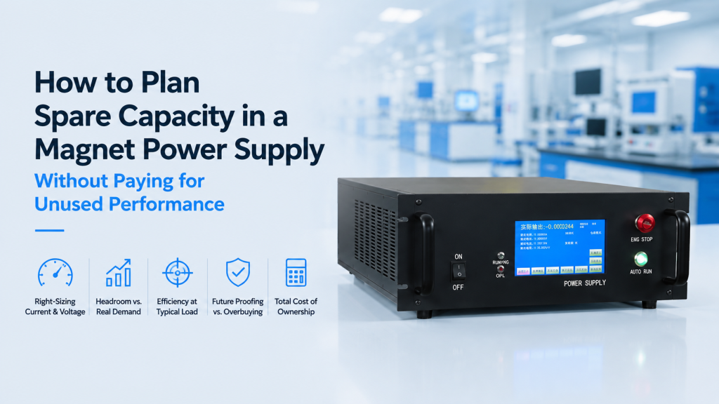
A laboratory needs a power supply for an electromagnet.
The magnet requires approximately:
- 40 A at maximum operating field
- 20 V at steady-state current
The first instinct is often:
“Let’s buy a much larger power supply so we have room for future upgrades.”
Perhaps:
- 60 A instead of 40 A
- 50 V instead of 20 V
- 3 kW instead of 800 W
More capacity must mean more flexibility, right?
Not necessarily.
For a magnet system, spare capacity only has value when it is available in the right electrical dimension.
A future requirement for faster current ramping may need more voltage, not more current.
A future requirement for higher magnetic field may need more current, but only if the magnet itself can safely accept it.
A superconducting magnet may need relatively little steady-state voltage but enough compliance voltage to achieve the required current ramp rate.
And buying a dramatically oversized supply can introduce:
- Higher purchase cost
- Larger electrical infrastructure
- More cooling
- More rack space
- Higher available fault energy
- Poorer utilization of the instrument’s useful operating range
- In some designs, less attractive absolute programming or readback resolution for low-current work
Good magnet power supply sizing is therefore not:
Required power × arbitrary safety factor.
It is:
Current requirement + voltage requirement + dynamic requirement + control requirement + credible future expansion.
Lake Shore’s Model 643 electromagnet power supply illustrates this system-level relationship clearly: its specifications define current, compliance voltage, load resistance, load inductance, slew rate, programming resolution, stability, four-quadrant capability, cooling, and line-power requirements together rather than describing the supply only by its kilowatt rating.
American Magnetics makes the same point from the superconducting side. Its Model 430 documentation gives the magnet charging relationship as:
V = L × dI/dt
and explains that the available voltage must support the required ramp rate together with additional circuit voltage drops.
The practical question for buyers is therefore:
How much capacity should we reserve for tomorrow without buying performance that the magnet, experiment, and laboratory may never use?
1. Start With the Magnet, Not the Power Supply Catalogue
Do not start by asking:
“Should we buy a 2 kW or 5 kW supply?”
Start with the load.
For an electromagnet, identify:
- Maximum required current
- Coil resistance
- Coil inductance
- Maximum field required
- Field-to-current relationship
- Required ramp or sweep rate
- Continuous or intermittent duty
- Cooling limit
Then determine what the power supply must provide.
The supply is part of the magnet system.
It should not be selected independently.
2. Current Capacity and Voltage Capacity Solve Different Problems
This distinction is central to magnet power supply sizing.
Current Capacity Mainly Determines
For a given magnet:
- Maximum achievable magnetization
- Maximum magnetic field, before magnetic saturation and thermal limits intervene
Voltage Capacity Mainly Determines
- Ability to overcome coil resistance
- Current ramp rate
- Dynamic response
- High-frequency or changing-field capability
A supply can therefore have:
- Plenty of current but insufficient voltage
or:
- Plenty of voltage but insufficient current.
Neither is properly sized.
3. For a Copper Electromagnet, Start With V = IR
At steady DC current, the first-order requirement is simple:
V = I × R
Suppose:
- Required current = 40 A
- Coil resistance = 0.5 Ω
Then:
V = 40 × 0.5 = 20 V
The magnet therefore requires approximately 20 V at 40 A under that resistance condition.
The steady-state electrical power is:
P = V × I = 800 W
or equivalently:
P = I²R = 800 W
But this does not mean an 800 W supply is automatically sufficient for every operating mode.
The magnet is inductive.
Dynamic operation adds another requirement.
4. Inductance Creates the Second Voltage Requirement
When current changes, the supply must also overcome the inductive voltage:
Vₗ = L × dI/dt
For a resistive-inductive magnet, a useful simplified relationship is:
V ≈ IR + L(dI/dt)
Suppose the same magnet has:
- R = 0.5 Ω
- L = 0.2 H
- I = 40 A
- Desired ramp rate = 10 A/s
Resistive voltage:
IR = 20 V
Inductive voltage:
L(dI/dt) = 2 V
Approximate required output while ramping near maximum current:
22 V
If you selected a power supply based only on the 20 V steady-state condition, it may not achieve the desired ramp rate.
This is why voltage headroom deserves separate consideration.
5. Faster Ramping Usually Needs Voltage Headroom
Suppose the same magnet must ramp at:
50 A/s
Now:
L(dI/dt) = 0.2 × 50 = 10 V
Near maximum current:
V ≈ 20 + 10 = 30 V
The magnet still only needs:
40 A
But the dynamic requirement has changed from approximately:
22 V → 30 V
Buying a 60 A / 22 V supply would not solve that problem.
A:
40–45 A / higher-voltage supply
might be much more useful.
Procurement Lesson
If future expansion means:
“We may need faster field sweeps.”
reserve voltage capability.
Do not automatically reserve current.
6. More Current Does Not Automatically Mean More Usable Field
Suppose the magnet is designed and thermally rated for:
40 A maximum continuous current.
You purchase a:
100 A power supply.
Can you now operate the magnet at 100 A?
No.
The magnet may be limited by:
- Coil temperature
- Cooling capacity
- Conductor current density
- Insulation
- Magnetic saturation
- Mechanical stress
The power supply being capable of 100 A does not change the magnet rating.
Important Principle
Power-supply capacity does not override magnet limits.
Unused current capacity may remain unused permanently.
7. The Magnet’s Field-vs-Current Curve Should Drive Current Headroom
Before buying substantial current headroom, ask for:
B vs. I
for the intended pole gap.
Suppose:
| Current | Field |
|---|---|
| 20 A | 0.30 T |
| 30 A | 0.47 T |
| 40 A | 0.60 T |
| 50 A | 0.68 T |
Notice what happens.
Going from:
40 A → 50 A
increases current by 25%.
But field increases from:
0.60 T → 0.68 T
only about 13%.
The magnetic circuit may be approaching saturation.
Buying substantially more current capability may therefore produce diminishing scientific value.
8. Spare Current Has Value Only If the Magnet Can Use It
Before reserving current headroom, ask:
- What is the magnet’s normal operating current?
- What is its maximum permitted current?
- What field does that additional current actually produce?
- Is the cooling system rated for it?
- Is continuous operation permitted?
- Does magnetic saturation make the extra current inefficient?
If the magnet’s maximum safe current is:
45 A
a 100 A supply is not a meaningful future-proofing strategy for that magnet.
9. Larger Future Pole Gaps Can Change Current Requirements
There is one legitimate reason to consider current margin:
A future experiment may require a larger working gap.
For example:
Current Experiment
Room-temperature sample holder:
20 mm gap
Future Experiment
Cryostat:
40 mm gap
For the same magnetic field, the larger gap may require significantly more magnetomotive force.
That can increase required current.
Therefore Ask Before Purchase
If cryogenic expansion is realistic:
- What future gap is expected?
- What field will be needed at that gap?
- What current will the existing magnet require?
- Is that current thermally acceptable?
Now current headroom is tied to a credible expansion path.
10. But Sometimes a Larger Gap Requires a Different Magnet
Do not assume extra current solves every future gap requirement.
Suppose:
Current system:
1 T at 20 mm
Future requirement:
1 T at 60 mm
The existing magnetic circuit may simply not be optimized for that geometry.
Achieving the future requirement might require:
- Larger pole diameter
- Larger yoke
- More copper
- Different coils
- Higher power
- Different cooling
In that case, oversizing today’s power supply may not prevent tomorrow’s magnet replacement.
Future-proof the system architecture, not merely the current rating.
11. Voltage Margin Should Be Connected to a Required Ramp Rate
A buyer sometimes asks:
“Give us 50% extra voltage.”
Why 50%?
A better process is:
- Determine coil inductance.
- Determine resistance at operating temperature.
- Define maximum desired dI/dt.
- Calculate approximate voltage requirement.
- Add appropriate engineering allowance for real circuit conditions.
Now the voltage rating has a physical purpose.
12. Coil Resistance Is Not Necessarily Constant
Copper resistance changes with temperature.
A coil that is:
0.40 Ω when cold
may have greater resistance after operating at high current.
That means the required DC voltage can rise during operation.
Therefore
Do not size compliance voltage using only:
cold resistance measured before operation
if the magnet is expected to operate continuously at high load.
Use a realistic operating resistance or manufacturer specification.
13. Current Margin and Thermal Margin Are Not the Same Thing
Suppose:
Power supply current limit:
60 A
Magnet rated continuous current:
40 A
Magnet allowed short-term current:
50 A
The system does not have:
20 A of useful continuous headroom.
Its real continuous margin is determined by:
the 40 A magnet thermal rating.
When comparing future capability, keep separate:
- Supply electrical limit
- Magnet thermal limit
- Cooling-system limit
The smallest may become the real system limit.
14. The Chiller Can Become the Hidden Capacity Limit
More current means more coil heating.
Since copper loss approximately follows:
P = I²R
current increases can create disproportionately more heat.
Example:
At 40 A:
P ∝ 40² = 1600
At 50 A:
P ∝ 50² = 2500
That is a:
56.25% increase in resistive heating
for a:
25% increase in current
assuming resistance remains unchanged.
So if you want future higher-current capability, check:
- Magnet cooling
- Chiller capacity
- Water flow
- Power-supply cooling
before paying for the larger current rating.
15. Facility Power Is Part of Spare-Capacity Cost
An oversized supply may require:
- Higher AC current
- Three-phase input
- Larger breaker
- Larger cable
- More cooling
- More rack space
Lake Shore’s Model 643, for example, is a ±70 A / ±35 V system with substantial line-power and cooling requirements, including three-phase input and specified cooling-water flow.
A larger supply may therefore cost more than the purchase-price difference.
Total Upgrade Cost May Include
Power supply + facility power + cooling + installation
If the spare output will never be used, those infrastructure costs also become unused capacity.
16. Do Not Use Kilowatts Alone to Compare Magnet Power Supplies
Consider:
Supply A
100 A × 10 V
≈1 kW
Supply B
20 A × 50 V
≈1 kW
They have approximately the same headline power.
They serve very different magnetic loads.
Supply A favors:
- High-current, low-resistance loads
Supply B favors:
- Lower-current loads requiring greater voltage
Therefore:
kW is not enough information for magnet power supply sizing.
Always compare:
- Current
- Voltage
- Operating envelope
17. “20% Spare Power” Is Not a Complete Design Rule
Suppose calculated requirement is:
1 kW
and someone says:
“Buy 1.2 kW for 20% margin.”
That does not tell you where the margin exists.
Perhaps you need:
- 10% additional current
- 40% additional voltage
or:
- No extra current
- Significant dynamic voltage
A single wattage margin hides the electrical requirement.
Better Approach
Plan separately:
- Current headroom
- Voltage headroom
- Dynamic/ramp headroom
- Thermal headroom
18. Four-Quadrant Capability Can Matter More Than Extra Power
For experiments requiring smooth:
+B → 0 → −B
operation, power-supply architecture matters.
A true four-quadrant supply can operate with positive and negative combinations of voltage and current, allowing it to source and sink energy and reverse current smoothly.
Lake Shore describes its Model 643 as a true four-quadrant bipolar current source designed for smooth positive-to-negative magnetic-field transitions without external polarity switching.
Kepco likewise describes four-quadrant magnet supplies as capable of sourcing and sinking power when driving inductive loads.
For:
- Hall
- MOKE
- Magnetic hysteresis
- Field cycling
this capability may add more experimental value than simply buying additional current.
19. An Inductive Magnet Stores Energy
The stored magnetic energy is approximately:
E = ½LI²
This matters when current decreases.
The stored energy must go somewhere.
Depending on system architecture, it may be:
- Returned through the power stage
- Absorbed internally
- Dissipated through an external energy absorber
- Dissipated through another protection circuit
Therefore, future faster ramp-down capability requires consideration of:
- Sink capability
- Voltage limits
- Energy handling
—not merely source power.
20. Fast Ramp-Up and Fast Ramp-Down Are Two Different Questions
A buyer may specify:
Ramp to 1 T quickly.
But what about returning to zero?
For an inductive load, a complete dynamic requirement should consider:
- Ramp up
- Ramp down
- Polarity reversal
- Emergency discharge where relevant
A power supply that can source current rapidly but cannot manage stored magnetic energy appropriately may not provide the desired field-cycling performance.
21. Superconducting Magnets Need a Different Sizing Mindset
A superconducting magnet is electrically very different from a copper electromagnet.
Once superconducting, the coil winding has extremely low DC resistance.
Steady-state voltage across the superconducting winding is therefore not dominated by:
IR
in the same way as a normal copper electromagnet.
During charging, the critical relationship is approximately:
V = L(dI/dt)
AMI explicitly uses this charging equation in its superconducting magnet programming documentation.
This changes what “spare capacity” means.
22. Superconducting Magnet Current Rating Still Matters
Suppose the magnet’s rated current is:
80 A
and its rated field is reached at 80 A.
Buying a:
150 A superconducting magnet power supply
does not mean the magnet can safely be driven to 150 A.
The magnet still has its:
- Rated current
- Quench limits
- Current-lead limits
- Protection requirements
Extra current capacity is only useful if:
- Another future magnet will use it
or:
- The system architecture explicitly requires it.
23. For Superconducting Magnets, Voltage Often Determines Charging Speed
Suppose:
- Magnet inductance = 10 H
- Desired ramp rate = 0.1 A/s
Then:
V = 10 × 0.1 = 1 V
If you want:
0.5 A/s
then:
V = 10 × 0.5 = 5 V
Current requirement has not changed.
The target magnet current may still be:
80 A
But the voltage requirement increased by a factor of five.
AMI notes that the voltage limit should account for the voltage needed for magnet charging plus applicable power-lead and energy-absorber voltage drops.
That is why superconducting magnet power-supply sizing should start with:
magnet inductance + permitted ramp rate + circuit voltage drops
rather than simply asking for more amperes.
24. The Magnet May Limit Ramp Rate Even If the Supply Has More Voltage
Suppose the power supply is capable of charging the magnet much faster.
That does not mean you should.
The magnet specification may impose a maximum ramp rate because of:
- Quench risk
- Mechanical forces
- Eddy-current heating
- Persistent-switch considerations
- System protection
AMI’s operating guidance explicitly instructs users not to exceed current, voltage, and ramp-rate limits specified for the magnet.
Therefore:
available power-supply voltage ≠ permitted magnet ramp rate.
25. Extra Voltage Has No Value If the Magnet Cannot Use the Faster Ramp
Suppose:
Existing supply can already support:
0.2 A/s
Magnet maximum permitted rate:
0.2 A/s
Buying enough voltage for:
1 A/s
produces no useful speed advantage on that magnet.
Again:
Future-proofing must be linked to a real future requirement.
26. Persistent-Mode Operation Changes the Workflow
Some superconducting magnet systems include a persistent switch.
In persistent mode, the magnet can maintain current after the external supply is effectively removed from the persistent loop.
The power supply may therefore be heavily used during:
- Charging
- Discharging
- Persistent-switch transitions
rather than continuously providing the full magnet current during every measurement.
This is another reason a simple:
field × current × “more is better”
approach does not describe superconducting power-supply requirements properly.
27. High-Stability Operation Is a Different Dimension of Performance
Consider two supplies:
Supply A
±50 A
Moderate stability
Supply B
±40 A
Much better stability
Your magnet requires:
±35 A maximum.
Which one is better?
If the experiment depends on:
- Field stability
- Low drift
- Low noise
Supply B may provide more scientific value despite having lower maximum current.
Spare Capacity Is Not Only Amperes
For precision experiments, also evaluate:
- Current stability
- Long-term drift
- Noise
- Temperature coefficient
- Line regulation
28. Do Not Sacrifice Precision for Capacity You Do Not Need
For a precision excitation system, the objective is not:
maximum possible current range.
It is:
appropriate current range + required precision.
Depending on instrument architecture, a larger current range may come with different:
- Absolute programming resolution
- Readback resolution
- Noise
- Stability specifications
For example, Lake Shore currently lists the ±70 A Model 643 with 0.1 mA programmed-current resolution, while its larger ±135 A Model 648 is specified with 1 mA programmed-current resolution. That does not establish a universal rule that larger supplies are less precise, but it illustrates why buyers should compare absolute control specifications rather than assuming more current is automatically better in every dimension.
29. Percentage Specifications Can Hide Important Absolute Values
Suppose a stability specification is expressed as:
ppm of full scale
or an analog monitor accuracy is specified as:
% of full scale.
If you choose a much larger current range than needed, the corresponding absolute error associated with a full-scale-based specification may be larger.
Therefore Compare Both
Relative specification
and
absolute current error.
For a low-field precision experiment, milliamperes may matter more than impressive full-scale capacity.
30. Define the Lowest Important Operating Current Too
Magnet buyers normally define:
maximum current.
They rarely define:
minimum scientifically important current.
Suppose the supply is 0–100 A.
But most measurements occur between:
0 and 2 A.
Then buyers should examine:
- Programming resolution
- Readback resolution
- Low-current noise
- Zero-current behavior
- Polarity crossover
The maximum current rating tells you almost nothing about this part of the experiment.
31. Zero Crossing Matters for Bipolar Magnetic Experiments
Hall and hysteresis measurements often require:
+I → 0 → −I
or equivalently:
+B → 0 → −B
Important characteristics may include:
- Smooth zero crossing
- Overshoot
- Residual current
- Polarity-reversal method
- Low-current control around zero
A larger maximum current rating does not guarantee better performance around zero.
For some experiments, that is more important than another 20 A of unused current capacity.
32. Analog Control Range Should Match the Real Operating Range
Suppose a supply maps:
±10 V analog input → ±100 A output
Then:
1 V → 10 A
If the experiment normally operates around:
±1 A
the external control system uses only a small fraction of the analog command range.
Depending on the full control chain, that may be less attractive than a properly scaled range.
Ask
- Is analog scaling configurable?
- Can current limits be programmed?
- Is there a lower-current range?
- What is external-command accuracy?
Again, spare capacity should not unnecessarily degrade effective system utilization.
33. Programmable Current Limits Are Valuable When the Supply Is Oversized
Sometimes there is a legitimate reason to buy one larger supply for several magnets.
In that case, protection becomes important.
Suppose:
Power supply:
±100 A
Magnet A maximum:
±30 A
Magnet B maximum:
±70 A
The control system should allow appropriate current limits so an operator cannot accidentally send:
100 A
through Magnet A.
Lake Shore’s Model 643, for example, includes programmable current and ramp-rate limits among its protection/control functions.
This makes intentional oversizing safer.
34. One Shared Power Supply Can Be a Rational Strategy
A laboratory may have several magnets that are not used simultaneously.
For example:
- Small electromagnet: 20 A
- Large electromagnet: 60 A
- Helmholtz coil: 10 A
A single carefully selected supply may reduce equipment duplication.
But evaluate:
- Voltage requirements
- Current requirements
- Inductance ranges
- Connector changes
- Control settings
- Protection limits
The highest current requirement alone does not define whether one supply suits all three loads.
35. Inductance Range Matters When One Supply Drives Multiple Magnets
Different magnets can have very different inductances.
A power supply designed for one load may behave differently with another.
Kepco specifically offers magnet-oriented four-quadrant supplies optimized for inductive loads, and its documentation discusses how load impedance and voltage limits affect current waveform performance.
Therefore, if one supply will serve multiple coils, provide the supplier with:
- R
- L
- Required current
- Required ramp/frequency
for every intended load.
36. AC or Modulated Field Changes the Sizing Problem
DC electromagnet operation is relatively straightforward.
If the field must vary periodically, additional parameters become critical:
- Frequency
- Amplitude
- Inductance
- Slew rate
- Voltage
- Power-supply bandwidth
The impedance of an inductive coil increases with frequency.
Therefore, a supply capable of:
±50 A DC
may not deliver:
±50 A at the desired AC frequency.
Lake Shore’s Model 643 specifications, for example, explicitly distinguish current capability, compliance voltage, load inductance, slew rate, and modulation performance.
Do Not Specify
“±50 A, 10 Hz”
without checking whether the magnet/power-supply combination can actually produce it.
37. Spare Frequency Capability Should Not Be Bought Accidentally
If the experiment is:
- Static Hall measurement
- Slow MOKE hysteresis
- DC magnetization
you may not need a high-bandwidth magnet driver.
A more dynamic supply may cost more and may be optimized differently from a high-stability DC source.
Choose based on:
experiment timescale
rather than:
maximum advertised bandwidth.
38. Separate Today’s Requirement From a Credible Future Requirement
A useful procurement table is:
| Parameter | Required Today | Credible Future |
|---|---|---|
| Maximum current | 40 A | 45 A |
| Steady-state voltage | 20 V | 23 V |
| Maximum ramp rate | 5 A/s | 15 A/s |
| Polarity | Bipolar | Bipolar |
| Stability | 25 ppm/h | 5 ppm/h |
| Interface | USB | USB + analog |
Now you can see what future-proofing actually means.
It may turn out that the future requirement is:
better stability
rather than:
more power.
39. Avoid Designing for an Undefined “Future Bigger Magnet”
This is one of the easiest ways to overspend.
Buyer says:
“We may buy a bigger magnet one day, so give us a very large power supply now.”
But nobody knows:
- Future coil resistance
- Future inductance
- Future current
- Future voltage
- Future cooling
- Future field
- Future timescale
A hypothetical magnet is not a specification.
Unless a plausible future load can be bounded, extreme oversizing is speculation.
40. Future Magnet Replacement Can Change Voltage as Much as Current
Suppose today’s magnet requires:
40 A / 20 V
A future magnet could require:
30 A / 60 V
because it has:
- Different wire
- Higher resistance
- Different inductance
- Different ramp requirement
Your oversized:
100 A / 25 V
supply still cannot drive it properly.
This demonstrates why generic “ampere headroom” is weak future planning.
41. Use a Future Load Envelope Instead
If future expansion is genuinely planned, define an electrical envelope.
For example:
Current Load
- ≤40 A
- ≤25 V
- L ≤0.3 H
Plausible Future Load
- ≤50 A
- ≤40 V
- L ≤0.5 H
- Maximum ramp 10 A/s
Now the power-supply supplier can evaluate a real design envelope.
This is much more meaningful than:
“Please give us 50% spare capacity.”
42. Separate Required Capacity From Protection Margin
Engineering margin is necessary.
But it should not be confused with functionality.
Functional Headroom
Supports a planned future requirement.
Engineering Margin
Allows for:
- Resistance variation
- Line variation
- Temperature
- Component tolerance
- Control operation
These are different reasons for extra capacity.
The supplier should account for engineering margin.
The buyer should decide whether additional functional headroom is worth paying for.
43. Avoid Operating Permanently at the Absolute Supply Limit
The opposite mistake is undersizing.
If your calculated requirement is exactly:
40.00 A / 20.00 V
buying a supply whose absolute boundaries are exactly:
40 A / 20 V
may leave no practical dynamic or operating margin.
Real systems include:
- Resistance variation
- Voltage drops
- Temperature changes
- Ramp requirements
So the correct recommendation is not:
“Never oversize.”
It is:
“Do not oversize blindly.”
44. Decide Which Limit You Expect to Approach
Ask:
Will the experiment normally operate near the supply’s:
- Current limit?
- Voltage limit?
- Power limit?
- Ramp-rate limit?
If the answer is:
all of them simultaneously
the supply may be too tightly sized.
If the answer is:
none—we will use only 20% of everything
it may be unnecessarily large.
Good sizing puts the real operating envelope comfortably inside the usable supply envelope without moving it needlessly far away.
45. Oversizing Can Increase Available Fault Energy
A power supply capable of much more current and voltage than the magnet requires can make configuration errors more consequential.
Protection therefore becomes increasingly important.
Look for:
- Programmable current limits
- Programmable voltage limits
- Ramp-rate limits
- Overtemperature protection
- Water-flow interlocks
- Emergency stop
- Magnet protection where applicable
Do not rely solely on the operator remembering:
“Never turn it above 40 A.”
46. Interlocks Are Part of Useful Capacity Planning
Suppose a future operating mode will use:
- Higher current
- Higher cooling load
Then future capacity should also include:
- Cooling-water monitoring
- Temperature protection
- Interlock logic
A larger power supply without the corresponding protection architecture may increase risk rather than flexibility.
47. Cable Size and Voltage Drop Can Matter at High Current
High-current systems require consideration of:
- Cable cross-section
- Cable length
- Connector rating
- Contact resistance
The power supply may have sufficient voltage at its terminals.
But some of that voltage may be lost in:
- Cables
- Connectors
- Current leads
For superconducting systems, AMI explicitly notes that power-lead voltage drop should be included when determining voltage limits for magnet charging.
For high-current copper magnet systems, cable loss is similarly worth including in the real circuit calculation.
48. Remote Sense Does Not Solve Every High-Current Problem
Voltage sensing can compensate for some lead drop in appropriate supply architectures.
But it does not eliminate:
- Cable heating
- Connector heating
- Current rating
- Energy loss
If future current increases substantially, cable and connector infrastructure may also need upgrading.
Future-proofing only the power-supply chassis may therefore be incomplete.
49. Multi-Axis Magnet Systems Need Channel-by-Channel Sizing
For:
- 2-axis
- 3-axis Helmholtz coils
- Vector magnet systems
do not simply multiply:
single-axis maximum current × number of axes
without understanding operating conditions.
Ask:
- Can all axes operate at maximum simultaneously?
- Are coil resistances identical?
- Are inductances identical?
- Is total cooling sufficient?
- Does each axis need four-quadrant control?
- Are vector trajectories required?
The useful spare capacity may differ by axis.
50. Simultaneous Operation Can Change Facility Requirements
Suppose each of three axes uses:
500 W maximum.
If only one axis normally operates near maximum, the real thermal profile differs from:
all three at maximum simultaneously.
Before buying oversized multi-channel capability, define:
- Worst credible vector field
- Simultaneous duty
- Cooling
- AC input power
Otherwise, the power electronics may be future-ready while the laboratory infrastructure is not.
51. Hall Systems Usually Benefit More From Stability and Reversal Than Extreme Headroom
For many Hall measurements, buyers need:
- Stable DC field
- Reliable ±B reversal
- Repeatable current setting
- Automation
They may not need:
- Very rapid field modulation
- Extreme excess current
For these applications, prioritize:
- Bipolar/four-quadrant operation
- Stability
- Low noise
- Smooth zero crossing
- Remote control
before buying a dramatically larger current range.
52. MOKE Requirements Can Be Different
MOKE experiments may involve repeated hysteresis loops.
Depending on measurement method, useful requirements may include:
- Bipolar operation
- Smooth reversal
- Defined sweep rate
- Repeatability
- Low overshoot
A higher compliance voltage may therefore be useful if it enables the required field sweep.
Again:
dynamic voltage can matter more than unused current.
53. VSM Power-Supply Requirements Should Follow Magnet Dynamics
VSM measurements can require:
- Stable field
- Repeated field sweeps
- Hysteresis loops
The power-supply requirement therefore depends on:
- Magnet resistance
- Magnet inductance
- Desired sweep speed
- Required stability
A power supply should be evaluated as part of:
magnet + measurement workflow
rather than as an isolated high-current source.
54. Superconducting Systems Should Be Sized Around the Exact Magnet
For superconducting magnet projects, ideally provide:
- Rated current
- Coil constant
- Inductance
- Permitted ramp rate
- Persistent-switch configuration
- Current-lead characteristics
- Required voltage limits
- Energy absorber/protection architecture
AMI’s power-supply/programmer documentation demonstrates this system-specific approach: when magnet, programmer, and supply are provided together, setup parameters such as current limit, magnet current rating, voltage limit, and ramp rate are configured to match the magnet.
That is much stronger than selecting a generic “high-current superconducting power supply.”
55. Upgradeability Can Come From Modularity Instead of Oversizing
Suppose you do not know whether future requirements will be:
- Higher current
- Higher voltage
- More channels
One strategy is to purchase a platform with:
- Modular architecture
- Series/parallel options where supported
- Upgradeable control
- Standard interfaces
rather than buying the largest possible supply immediately.
This can preserve flexibility without paying today for an undefined future operating point.
Whether this is feasible depends on the supply architecture.
56. Interfaces Can Be Better Future-Proofing Than Watts
Future laboratories often care about integration.
Useful features can include:
- USB
- Ethernet
- RS-232 / RS-485
- GPIB
- Analog input
- Current monitor output
- Trigger
- Interlock
A supply with adequate output and well-documented interfaces may remain useful longer than a larger but closed system.
If future automation is credible, interface capability deserves explicit planning.
57. Do Not Forget Line Voltage When Buying for International Use
High-power magnet supplies may require:
- 200/208 VAC
- 220/230 VAC
- 380/400/415 VAC
- Single or three phase
depending on model.
Lake Shore’s Model 643, for example, supports several specified three-phase line-voltage configurations, which must be considered as part of installation planning.
Buying more output capacity can move the system into a more demanding facility-power class.
That infrastructure cost belongs in the purchasing decision.
58. A Weak Power-Supply RFQ
A buyer writes:
We need a magnet power supply for a 40 A electromagnet. Please quote a 60 A or larger unit so that we have spare capacity for future use.
The supplier still does not know:
- Coil resistance
- Coil inductance
- Required voltage
- Ramp rate
- Bipolar requirement
- Stability
- Future load
- Analog/digital control
- Continuous duty
The “60 A” target may solve the wrong problem.
59. A Better Power-Supply RFQ
The present electromagnet requires approximately 40 A maximum, with an operating coil resistance of approximately 0.5 Ω and inductance of approximately 0.2 H. The present experiment uses bipolar DC operation with field sweeps corresponding to a maximum current ramp of approximately 10 A/s. Future experiments may require up to approximately 45 A and a faster ramp of 20 A/s, but no larger magnet is currently planned.
Please recommend an appropriate four-quadrant power supply with sufficient current and compliance-voltage margin for these conditions. Please also state current stability, programming resolution, ramp-rate capability, analog/remote interfaces, and cooling/site requirements.
Now the supplier can optimize the system intelligently.
60. What Buyers Should Ask Before Paying for Spare Capacity
Magnet
- Maximum rated current?
- Coil resistance?
- Resistance at operating temperature?
- Inductance?
- Field vs. current?
- Cooling limit?
Current
- Present maximum?
- Realistic future maximum?
- Can the magnet safely use it?
Voltage
- Steady-state IR requirement?
- Ramp requirement?
- Cable/lead drop?
- Future ramp requirement?
Dynamics
- Maximum dI/dt?
- Field sweep rate?
- AC/modulation frequency?
- Ramp-down requirement?
Precision
- Stability?
- Ripple?
- Programming resolution?
- Readback resolution?
- Zero-current performance?
Architecture
- Bipolar?
- Four quadrant?
- Source and sink?
- Energy handling?
Integration
- Analog control?
- USB?
- Ethernet?
- LabVIEW/Python?
Facility
- AC input?
- Cooling water?
- Chiller?
- Rack space?
Future
- Actual defined upgrade?
- Or only hypothetical “maybe someday”?
If these questions are answered, spare capacity becomes an engineering choice rather than an insurance purchase.
61. A Practical Capacity Planning Method
A useful workflow is:
Step 1 — Define Today’s Load
Determine:
- R
- L
- Imax
Step 2 — Define Today’s Dynamics
Determine:
- dI/dt
- polarity
- duty cycle
Step 3 — Calculate the Electrical Envelope
Estimate:
V ≈ IR + L(dI/dt)
where applicable.
Step 4 — Define Precision Requirements
- Stability
- Noise
- Resolution
Step 5 — Define One Credible Future Scenario
Not five hypothetical systems.
Step 6 — Recalculate the Future Envelope
Current and voltage separately.
Step 7 — Check Magnet and Cooling Limits
Can the physical magnet actually use the spare output?
Step 8 — Check Facility Cost
Will the larger supply require additional:
- Power
- Cooling
- Infrastructure?
Step 9 — Select the Smallest Supply That Comfortably Covers the Agreed Envelope
That is sensible future-proofing.
62. How Cryomagtech Approaches Magnet Power Supply Sizing
Cryomagtech evaluates a magnet power supply as part of the magnetic system rather than selecting it from maximum current alone.
Depending on the project, the evaluation can include:
- Magnet resistance
- Magnet inductance
- Maximum current
- Compliance voltage
- Required magnetic field
- Field vs. current
- Current stability
- Ramp rate
- Bipolar / four-quadrant operation
- Analog control
- Digital communication
- Cooling
- Continuous duty
- Future magnet or gap changes
For superconducting systems, additional considerations include:
- Magnet rated current
- Inductance
- Allowed ramp rate
- Persistent-switch operation
- Voltage limits
- Energy handling and protection
For quotation purposes, providing the magnet’s:
R + L + Imax + required dI/dt
is far more useful than simply asking for:
“a power supply with 30% spare capacity.”
It allows the reserve capacity to be placed where the experiment can actually use it.
63. Key Takeaways
- Good magnet power supply sizing is not based on wattage alone.
- Current and voltage headroom solve different engineering problems.
- For a resistive-inductive electromagnet, a useful first-order relationship is V ≈ IR + L(dI/dt).
- Higher field may require more current, but only if the magnet’s thermal and magnetic design can use it.
- Faster current ramping primarily increases the inductive voltage requirement.
- A larger future pole gap may change required current and may sometimes require a different magnet entirely.
- Copper heating scales approximately with I²R, so modest current increases can substantially increase thermal load.
- Extra current capacity is useless if the magnet, chiller, cables, or facility cannot support it.
- A power rating such as “2 kW” does not tell you whether the available current/voltage operating envelope suits the magnet.
- Four-quadrant source/sink operation may add more experimental value than extra unused current for bipolar magnetic measurements.
- For superconducting magnets, charging voltage is strongly related to V = L(dI/dt), making inductance and ramp rate central sizing parameters.
- Higher power-supply capability does not allow a superconducting magnet to exceed its rated current or ramp-rate limit.
- Precision buyers should compare stability, noise, absolute programming resolution, readback resolution, and zero-crossing behavior in addition to maximum current.
- Oversized supplies should use appropriate current, voltage, and ramp-rate limits to protect smaller loads.
- Multi-axis and multi-magnet systems should be evaluated load by load rather than from one maximum-current number.
- AC or modulated magnetic fields require attention to inductance, compliance voltage, bandwidth, and slew rate.
- Facility power and cooling are part of the cost of spare capacity.
- Future-proofing is most useful when tied to one credible future load envelope.
- If the future load is completely unknown, extreme oversizing may simply buy unused capability.
The weak purchasing rule is:
“Our magnet needs 40 A, so let’s buy 60 or 80 A to be safe.”
The stronger approach is:
“Our present and credible future loads require these current, voltage, ramp-rate, stability, and interface capabilities. Let’s buy enough margin to cover that envelope—and no more than the experiment can realistically use.”
That is how spare capacity becomes useful engineering rather than unused performance.