
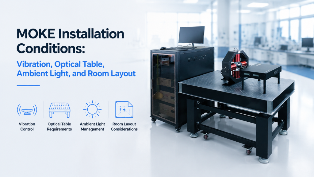
A MOKE system can meet every specification on paper and still perform poorly after installation.
The problem is often not the laser, detector, electromagnet, or software. It is the room.
Uncontrolled vibration can move the laser spot. Ambient light can increase detector noise. Air-conditioning can disturb an open optical path. An unsuitable table can allow the magnet, sample, and optical head to move relative to one another. Poor room planning can also leave insufficient space for the power supply, cooling system, electrical connections, and future maintenance.
For buyers, understanding the required MOKE installation conditions before placing an order is essential. It reduces commissioning delays, prevents avoidable signal problems, and helps distinguish an instrument issue from an installation issue.
This guide explains how to evaluate vibration, optical-table requirements, ambient light, airflow, utilities, and laboratory layout before a MOKE system arrives.
1. Why MOKE Installation Conditions Affect Measurement Quality
The Magneto-Optical Kerr Effect is detected through a change in the polarization state or intensity of light reflected from a magnetized sample.
In practical measurements, the useful Kerr signal may be much smaller than several unwanted effects, including:
- Mechanical movement
- Laser-intensity drift
- Detector noise
- Ambient and stray light
- Sample-position changes
- Optical misalignment
- Thermal expansion
- Electromagnetic interference
- Reflections from fixtures and chamber windows
A MOKE system therefore depends on more than the sensitivity stated in a datasheet.
The installed system must maintain a stable relationship between:
- The laser source
- Polarization optics
- Focusing optics
- Sample surface
- Applied magnetic field
- Reflected beam
- Photodetector or camera
If any of these elements moves during a field sweep, the system may detect a change that is mechanical or optical rather than magnetic.
This does not mean every MOKE system requires an expensive purpose-built laboratory. It means the installation standard should match the measurement objective.
2. Not Every MOKE System Needs the Same Laboratory
Before specifying an optical table or dark enclosure, buyers should identify the type of MOKE measurement they plan to perform.
Routine Hysteresis-Loop Measurement
A compact point-MOKE system used for routine hysteresis loops may be relatively tolerant of normal laboratory conditions, especially when:
- The optical path is short and enclosed
- The optical head is mechanically integrated
- The sample holder is rigid
- The measurement uses signal modulation
- The laser spot is not extremely small
- The laboratory floor is reasonably stable
Such a system may operate successfully on a rigid laboratory bench or integrated instrument frame.
Micro-MOKE Measurement
A micro-MOKE system focuses the laser onto a much smaller sample area.
As spot size decreases, the system becomes more sensitive to:
- Sample-stage movement
- Table vibration
- Thermal drift
- Building vibration
- Focus changes
- Local surface nonuniformity
A movement that is insignificant for a millimeter-scale laser spot may become serious when measuring a patterned device or microscopic region.
MOKE Microscopy and Magnetic Domain Imaging
Camera-based Kerr microscopy introduces additional requirements because the system must preserve image position, focus, contrast, and field of view.
The installation may require:
- A vibration-isolated optical table
- A stable microscope structure
- Controlled ambient light
- Reduced air movement
- Thermal stabilization
- A rigid sample and magnet assembly
Cryogenic or Vacuum MOKE
Adding a cryostat or vacuum chamber increases the mechanical and optical complexity.
The installation must then accommodate:
- Vacuum pumps
- Cryogenic compressors
- Cooling-water lines
- Optical windows
- Longer working distances
- Additional cables
- Sample-temperature controllers
- Pump-induced vibration
- Thermal contraction and drift
The correct MOKE installation conditions therefore depend on the full system configuration, not simply on the term “MOKE.”
3. Vibration: The Most Common Hidden Installation Risk
How Vibration Enters a MOKE Measurement
Vibration can move the sample, optical head, objective, detector, or magnet.
The result may appear as:
- A fluctuating detector baseline
- Reduced signal-to-noise ratio
- An unstable laser spot
- Image movement
- Apparent hysteresis-loop distortion
- Poor repeatability
- Loss of focus
- Different results before and after nearby equipment starts
Optical systems are affected by relative motion between components. A good installation does not merely prevent the entire system from moving; it minimizes movement of one critical component relative to another.
Newport’s optical-table guidance distinguishes between vibration isolation and damping. Isolators reduce vibration transmitted from the floor, while the table structure and damping system suppress resonances on the tabletop itself.
Common Sources of Laboratory Vibration
Potential vibration sources include:
- People walking near the system
- Doors opening and closing
- Elevators
- Road traffic
- Construction
- Building ventilation systems
- Air compressors
- Water chillers
- Vacuum pumps
- Cryocooler compressors
- Mechanical pumps
- Centrifuges
- Machine tools
- Rooftop mechanical equipment
Some vibration sources are continuous. Others appear only at particular times.
A laboratory may seem quiet during installation but become unstable when:
- The building’s ventilation switches operating mode
- A neighboring laboratory starts a pump
- Traffic increases
- A nearby elevator operates
- A cooling compressor cycles
- More people enter the corridor
Low-Frequency and High-Frequency Vibration
Low-frequency vibration often comes from:
- Building sway
- Foot traffic
- Elevators
- Road traffic
- Large mechanical systems
Higher-frequency vibration may come from:
- Fans
- Pumps
- Chillers
- Motorized stages
- Cooling-water turbulence
- Loose optical mounts
Different isolation systems perform differently across frequency ranges. A heavy table alone does not automatically solve every vibration problem.
4. Does a MOKE System Require an Optical Table?
The honest answer is: sometimes, but not always.
A buyer should avoid both extremes:
- Assuming any ordinary desk is sufficient
- Assuming every MOKE system requires the most expensive active-isolation table
A Rigid Bench May Be Sufficient When
A rigid laboratory bench may be acceptable for:
- Compact integrated MOKE instruments
- Enclosed optical heads
- Routine macroscopic hysteresis loops
- Relatively large laser spots
- Short optical paths
- Non-imaging measurements
- Laboratories with low floor vibration
- Systems designed and tested as a single mechanical assembly
The bench should still be:
- Mechanically rigid
- Level
- Stable under the full equipment load
- Free from rocking or flexing
- Separate from frequently used work surfaces
An ordinary office desk, wheeled table, folding table, or lightweight wooden bench is normally a poor choice.
A Passive-Isolation Optical Table Is Recommended When
Passive pneumatic isolation is often appropriate for:
- Open optical-path systems
- Micro-MOKE measurements
- Small laser spots
- Kerr microscopy
- Long-duration measurements
- Motorized sample scanning
- Sensitive polarization measurements
- Laboratories with noticeable floor vibration
Pneumatic isolators reduce the transfer of floor vibration to the optical surface, while a damped tabletop reduces resonant motion across the setup.
Active Damping or Higher-Performance Isolation May Be Needed When
More advanced vibration control may be justified for:
- High-magnification domain imaging
- Very small patterned devices
- Long-exposure imaging
- Nanopositioning
- Strong acoustic noise
- Difficult building environments
- Upper-floor laboratories
- Sites close to roads, railways, or heavy machinery
This decision should ideally be based on an environmental vibration survey rather than assumptions.
5. Optical Table Selection: More Than Length and Width
Buyers often specify only the table dimensions. That is not enough.
Load Capacity
The table and support system must safely carry:
- Electromagnet
- Optical head
- Sample stage
- Microscope
- Cryostat or vacuum chamber
- Translation stages
- Optical mounts
- Cables and support structures
The total static load is important, but so is load distribution.
A large electromagnet concentrated near one end of the table can create a very different mechanical condition from an evenly distributed optical setup.
Table Rigidity
The table must resist deformation when:
- The magnet is installed
- The sample stage moves
- A cryostat is added
- An operator adjusts the system
- Equipment is repositioned
Newport notes that optical tables are intended to reduce errors caused by relative motion between optical components and that both static and dynamic rigidity matter when loads move or environmental forces act on the system.
Damping and Isolation Are Different
A buyer should distinguish:
- Isolation: reducing vibration transmitted from the floor
- Damping: reducing resonance within the table and installed structure
- Rigidity: limiting deformation between mounted components
A table may have a rigid top but no floor isolation. Another may have pneumatic legs but insufficient damping for the installed structure.
Pneumatic Air Requirements
Pneumatic isolators may require:
- A clean compressed-air source
- A suitable pressure range
- Air tubing
- A regulator
- Space for valves and connections
- Periodic inspection
Confirm whether the table uses:
- Continuous air supply
- Initial inflation only
- Self-leveling pneumatic supports
- Manual leveling supports
Do not discover the air-supply requirement after delivery.
Magnetic Compatibility
A standard optical table contains steel and may interact with strong or spatially extended magnetic fields.
For many MOKE systems, this does not create a practical problem because the field is concentrated near the magnet gap. However, buyers should evaluate magnetic compatibility when:
- The electromagnet has substantial stray field
- Earth-field-level measurements are required
- Highly sensitive field sensors are nearby
- The setup uses large Helmholtz coils
- Magnetic shielding is part of the experiment
- A non-magnetic environment is required
In these cases, the supplier should review the table material, magnet position, and distance to nearby ferromagnetic structures.
6. Never Place the Main Vibration Sources on the Optical Table
An optical table cannot protect an experiment from equipment mounted directly on the same table.
Whenever possible, keep the following off the optical surface:
- Water chillers
- Vacuum pumps
- Cryogenic compressors
- Mechanical roughing pumps
- Air compressors
- Large power supplies with cooling fans
- Computer towers
- Uninterruptible power supplies
- Transformers
- Frequently handled tools
Use Separate Floor-Mounted Equipment
Supporting equipment should preferably be installed:
- On the floor
- On a separate rigid equipment rack
- Outside the optical enclosure
- Away from the sample and detector
- With sufficient ventilation
- Within the permitted cable and hose length
Avoid Rigid Vibration Bridges
Even floor-mounted pumps can transmit vibration through:
- Vacuum hoses
- Cooling-water tubes
- Electrical conduits
- Rigid metal pipes
- Cable bundles under tension
Use suitable flexible connections and strain relief where permitted by the system design.
However, longer flexible lines are not automatically better. Excessively long vacuum or cooling lines can reduce performance, increase pressure loss, or create unstable mechanical loads.
The correct arrangement should be reviewed before installation.
7. Ambient Light and Stray Light
Why Ambient Light Matters
The MOKE detector is intended to measure light reflected from the sample.
Unwanted light can also reach the detector from:
- Ceiling lamps
- Sunlight
- Windows
- Computer monitors
- Mobile phones
- Indicator LEDs
- Illuminated switches
- Reflections from metallic surfaces
- Light leaking around an enclosure
- Scattering from optical mounts
This unwanted light can increase the detector background, reduce available dynamic range, and add fluctuations unrelated to the sample.
Thorlabs recommends measures such as turning off room lights, using a light-tight enclosure, redirecting displays, and covering unwanted LEDs when ambient light affects a sensitive optical detector. It also notes that stray light may scatter or reflect through multiple paths before overlapping the intended beam.
Does MOKE Require a Dark Room?
Not necessarily.
A full dark room may be unnecessary when:
- The optical path is enclosed
- The detector has appropriate filtering
- The laser wavelength is well selected
- Signal modulation and lock-in detection are used
- The system has effective stray-light control
- Room lighting is stable
However, a darkened or controllable-light environment can significantly improve commissioning and troubleshooting.
The real requirement is not “complete darkness.” It is a controlled and repeatable optical background.
Sunlight Is Particularly Problematic
Direct or changing sunlight can create:
- Rapid detector-background changes
- Thermal gradients
- Reflections
- Sample heating
- Optical-table bending
- Daily variation in measurement conditions
Avoid placing the system directly beside an uncovered window.
Recommended measures include:
- Blackout curtains
- Light-blocking blinds
- An optical enclosure
- Relocating the system away from windows
- Using a room without direct sunlight
Fluorescent and LED Lighting
Some artificial lighting systems introduce time-dependent intensity fluctuations.
Even when those fluctuations are not obvious to the eye, they may affect sensitive detectors or interact with the measurement frequency.
The preferred approach is to:
- Test with room lighting on and off
- Maintain stable lighting during measurements
- Enclose the detector path
- Use wavelength-appropriate optical filtering
- Avoid placing lamps directly above the open beam path
Monitor and Indicator-Light Control
Small light sources are often overlooked.
Potential problems include:
- A monitor facing the detector
- A flashing network indicator
- A temperature controller display
- A power-supply status LED
- A mobile phone screen
- A camera autofocus light
During troubleshooting, temporarily cover or switch off these sources to identify whether they influence the baseline.
8. Optical Enclosures: Light Control, Airflow Control, and Safety
An enclosure can improve more than ambient-light rejection.
Benefits of an Optical Enclosure
A properly designed enclosure can reduce:
- Stray light
- Air currents
- Dust contamination
- Accidental optical-path disturbance
- Direct exposure to the laser beam
- Rapid temperature fluctuations
Commercial optical-table enclosures are specifically designed to shield optics from disruptive air currents and may use dark surfaces to reduce stray-light interference.
An Enclosure Is Not Automatically Light-Tight
Clear acrylic panels may reduce airflow and dust without completely eliminating ambient light.
Buyers should clarify whether the enclosure is intended for:
- Airflow reduction
- Dust protection
- Laser safety
- Partial light reduction
- Full light-tight operation
- Acoustic reduction
These are different functions.
Avoid Contact With the Optical Setup
The enclosure should not:
- Rest against the electromagnet
- Touch sensitive optical mounts
- Pull on cables
- Restrict sample-stage movement
- Transfer building vibration into the optical structure
Doors and panels should open without disturbing the aligned beam path.
Allow Sufficient Heat Removal
An enclosure can trap heat generated by:
- Electromagnet coils
- Cameras
- Motorized stages
- Illumination sources
- Electronics
- Temperature-control hardware
The enclosure design must balance optical protection with safe ventilation.
Do not enclose a heat-generating electromagnet or power device without confirming the cooling requirements.
9. Airflow and Temperature Stability
Why Air Conditioning Can Affect MOKE
Air movement can influence an open optical setup by:
- Moving lightweight components
- Creating temperature gradients
- Changing the refractive index along the beam path
- Cooling one side of a structure
- Causing slow alignment drift
- Moving cables or protective covers
Avoid placing the MOKE system directly under:
- Air-conditioning outlets
- Ceiling fans
- Supply-air vents
- Return-air grilles
- Frequently opened exterior doors
Temperature Stability Matters More Than a Single Temperature Value
Most laboratories focus on whether the room is at 20 °C, 22 °C, or 25 °C.
For optical stability, rapid variation may be more damaging than the exact setpoint.
Temperature changes can alter:
- Optical-mount dimensions
- Magnet resistance
- Laser behavior
- Detector response
- Sample-stage position
- Focus
- Cryostat alignment
- Optical-table shape
Newport notes that nonuniform temperature changes can cause slow structural bending and recommends environmental control and thermally insensitive design to reduce these effects.
Recommended Operating Practice
For sensitive measurements:
- Allow the room temperature to stabilize
- Allow the laser and electronics to warm up
- Avoid changing air-conditioning settings during a test
- Keep heat-generating equipment away from the optical path
- Avoid direct sunlight
- Minimize opening the enclosure during long measurements
- Record room conditions when investigating unexplained drift
The required stabilization time should come from the system supplier’s operating procedure rather than a universal assumption.
10. Room Layout: Plan the Entire System, Not Just the Main Unit
A MOKE purchase may include more equipment than buyers initially expect.
Possible components include:
- Optical table or workstation
- Electromagnet
- MOKE optical head
- Laser and detector modules
- Sample stage
- Magnet power supply
- Water chiller
- Control computer
- Monitor
- Electronics rack
- Vacuum pump
- Cryogenic compressor
- Temperature controller
- Gas cylinders
- Electrical measurement instruments
A floor plan should be prepared before shipping.
Operator Access
The operator should be able to reach:
- Sample holder
- Optical alignment controls
- Magnet gap
- Emergency stop
- Power-supply controls
- Computer
- Cryostat connections
- Enclosure doors
Do not place the system so close to a wall that sample exchange or optical alignment becomes impossible.
Maintenance Access
Leave space for:
- Removing optical panels
- Inspecting water connections
- Cleaning optical components
- Replacing cables
- Servicing the magnet
- Accessing electrical terminals
- Moving the chiller
- Opening electronics racks
A system that fits into a room with only a few centimeters to spare may not be serviceable.
Cable and Hose Routing
Plan routes for:
- Magnet power cables
- Hall-sensor cables
- Detector cables
- Motor-control cables
- USB or Ethernet connections
- Cooling-water hoses
- Vacuum hoses
- Cryogenic lines
- Temperature-sensor wiring
Cables should not:
- Cross walking paths without protection
- Pull on optical components
- Block ventilation
- Hang from moving stages
- Form trip hazards
- Lie against hot surfaces
- Create unnecessary electrical loops
Separation of Optical and Utility Zones
A practical layout often divides the room into:
- A stable optical zone
- An operator-control zone
- A power and cooling zone
- A pump or compressor zone
- A sample-preparation zone
This prevents routine activities from disturbing the aligned system.
11. Electromagnet and Power-Supply Placement
The magnet is part of the optical measurement structure, but the power supply usually does not need to be on the optical table.
Electromagnet Placement
The magnet should be:
- Mechanically secure
- Properly supported
- Aligned with the sample stage
- Accessible for gap adjustment
- Compatible with the table load capacity
- Positioned to preserve the optical path
For heavy magnets, confirm:
- Lifting method
- Center of gravity
- Mounting-hole pattern
- Table deflection
- Installation personnel requirements
Power-Supply Placement
The magnet power supply should normally be positioned:
- On a separate rack or floor stand
- Within the permitted cable length
- With sufficient cooling airflow
- Away from sensitive optical detectors
- Where front and rear panels remain accessible
Potential issues include:
- Fan vibration
- Acoustic noise
- Electromagnetic interference
- Heat output
- High-current cable routing
Avoid Unplanned Cable Extensions
Extending magnet cables can affect:
- Voltage drop
- Dynamic response
- Stability
- Cable heating
- Electromagnetic emissions
- Calibration assumptions
Any extension should be approved by the supplier.
12. Water Cooling and Chiller Installation
Water-cooled electromagnets may require a dedicated chiller or facility-water connection.
Confirm the Cooling Requirements
The buyer should obtain:
- Required flow rate
- Inlet-temperature range
- Maximum inlet pressure
- Permitted pressure drop
- Cooling capacity
- Water-quality requirement
- Hose size and connection type
- Alarm or interlock requirements
Chiller Placement
The chiller should normally be installed:
- Off the optical table
- On a stable floor
- With adequate ventilation
- Away from the detector
- Within permitted hose length
- Where filters and reservoirs remain accessible
Condensation Risk
Cooling water below the room’s dew point can cause condensation on:
- Magnet coils
- Hoses
- Fittings
- Pole structures
- Nearby optical components
The cooling-water setpoint should be selected with room humidity in mind.
Leak Management
A practical installation may include:
- Leak trays
- Flow sensors
- Temperature alarms
- Hose clamps
- Shutoff valves
- Periodic inspection
- Water-leak detectors
The room layout should keep water connections away from unprotected electrical equipment wherever possible.
13. Vacuum Pumps and Cryogenic Equipment
Pump-Induced Vibration
Vacuum pumps are among the most common external vibration sources in cryogenic or vacuum MOKE installations.
Whenever possible:
- Place the pump on the floor
- Use an appropriate flexible vacuum hose
- Avoid direct mechanical contact with the optical table
- Use a suitable isolation platform
- Keep the pump away from the detector
- Confirm that the hose does not pull on the chamber
Cryocooler Compressors
Closed-cycle cryogenic systems may include:
- Helium compressors
- Cold heads
- Flexible gas lines
- Cooling-water connections
- Mechanical pumps
These systems can introduce periodic vibration that cannot be treated in the same way as ordinary floor noise.
The MOKE supplier and cryostat supplier should jointly review:
- Cold-head orientation
- Sample vibration
- Optical working distance
- Compressor placement
- Line routing
- Measurement synchronization
- Acceptable image or spot movement
Pump Shutdown Is Not Always an Acceptable Solution
Some users assume they can stop the vacuum pump during measurement.
That may be possible for certain chamber designs, but it should not be assumed. Pump shutdown can affect:
- Vacuum pressure
- Sample temperature
- Contamination
- Cryostat operation
- Measurement duration
The operating procedure must be defined before purchase.
14. Electrical Supply, Grounding, and Noise Control
Confirm Utility Power Before Delivery
The buyer should verify:
- Supply voltage
- Frequency
- Single-phase or three-phase requirement
- Maximum current
- Connector or terminal type
- Circuit-breaker rating
- Protective-earth connection
- Local electrical regulations
The main MOKE unit, magnet power supply, chiller, pump, and cryogenic equipment may have different electrical requirements.
Use Dedicated Circuits Where Appropriate
High-current magnet power supplies and chillers should not automatically share a circuit with:
- Sensitive detectors
- Low-noise amplifiers
- Lock-in amplifiers
- Measurement computers
- Precision electrical instruments
A dedicated electrical circuit can help reduce voltage disturbances and simplify fault diagnosis.
Grounding Must Be Planned as a System
Poor grounding can cause:
- Detector noise
- Communication errors
- Unstable analog signals
- Ground loops
- Safety risks
However, randomly adding extra ground wires can make the problem worse.
The grounding arrangement should follow the supplier’s wiring diagram and local safety requirements.
Electromagnetic Interference
Potential interference sources include:
- Magnet power supplies
- Variable-frequency drives
- Large motors
- Radio transmitters
- Switching power supplies
- High-current cables
- Microwave equipment
- Nearby magnets
Keep sensitive detector cables separated from high-current magnet cables where practical.
15. Magnetic Environment and Nearby Ferromagnetic Objects
MOKE systems intentionally generate magnetic fields. The room must therefore be reviewed for both measurement effects and safety.
Nearby Magnetic Materials
Large ferromagnetic objects may distort the applied field or alter the stray-field distribution.
Examples include:
- Steel cabinets
- Heavy steel benches
- Tool carts
- Gas cylinders
- Reinforced structures
- Magnetic fixtures
- Large transformers
The importance of these objects depends on:
- Magnet design
- Pole gap
- Operating field
- Required field accuracy
- Distance from the magnet
- Whether the experiment operates near the Earth-field level
Moving Objects Can Be Worse Than Fixed Objects
A fixed steel cabinet may produce a stable influence.
A moving object can cause a changing influence.
Avoid routinely moving the following near a sensitive setup:
- Steel chairs
- Toolboxes
- Magnetic sample holders
- Large instruments
- Gas cylinders
- Magnetic carts
Pacemakers and Magnetic Media
Strong magnetic fields may affect:
- Pacemakers and implanted medical devices
- Magnetic storage media
- Watches
- Phones
- Credit cards
- Magnetically sensitive instruments
The system supplier should provide appropriate magnetic-field and laboratory-safety guidance.
16. Laser Safety and Room Control
A MOKE system uses a laser, even when the output power appears modest.
The installation should be reviewed according to:
- Laser wavelength
- Laser class
- Beam height
- Open or enclosed beam path
- Reflected-beam direction
- Sample reflectivity
- Viewing optics
- Access by untrained personnel
Reflective Samples Require Special Attention
MOKE commonly measures reflective metallic films.
Unexpected reflections can come from:
- Sample surfaces
- Magnet poles
- Cryostat windows
- Probe needles
- Metallic fixtures
- Optical mounts
A beam dump and controlled optical path are important.
Room Access
Depending on the system classification and local rules, the room may require:
- Warning labels
- Controlled entry
- Laser eyewear
- Beam enclosures
- Interlocks
- Emergency shutdown
- Operator training
Do not treat room-darkening panels as laser-safety barriers unless they are designed and certified for that purpose.
17. Delivery Route and Physical Installation
Installation planning starts before the equipment reaches the laboratory.
Measure the Complete Delivery Route
Confirm:
- Building entrance width
- Corridor width
- Door width and height
- Elevator dimensions
- Elevator load capacity
- Stair access
- Turning radius
- Loading-dock access
- Final room entrance
- Ceiling height
A large optical table may not fit through a standard laboratory door after assembly.
Floor Capacity
The combined weight may include:
- Optical table
- Support frame
- Electromagnet
- Cryostat
- Optical equipment
- Enclosure
- Operator load
For large systems, the building or facility team should confirm floor-loading suitability.
Lifting and Handling
Heavy electromagnets may require:
- A pallet jack
- A forklift
- A gantry
- A lifting frame
- A crane
- Multiple trained installers
The magnet should never be lifted by cooling-water fittings, pole-adjustment mechanisms, cables, or optical mounts.
18. A Practical Room-Layout Example
A typical MOKE laboratory can be divided into four zones.
Zone A: Optical Measurement Area
Contains:
- Optical table
- Electromagnet
- Optical head
- Sample stage
- Cryostat or chamber
- Optical enclosure
This should be the most stable and least disturbed area.
Zone B: Operator Area
Contains:
- Monitor
- Keyboard
- Control computer
- Frequently used controllers
- Sample records
The operator should not need to lean against the optical table during normal measurement.
Zone C: Power and Cooling Area
Contains:
- Magnet power supply
- Chiller
- Electrical distribution
- Electronics rack
This area needs ventilation and maintenance access.
Zone D: Pump and Utility Area
Contains:
- Vacuum pump
- Cryogenic compressor
- Gas controls
- Facility connections
This area should be mechanically separated from the optical measurement zone as far as the system design reasonably permits.
19. MOKE Installation Conditions Checklist Before Purchase
Before requesting a final quotation, the buyer should provide the following information.
Room and Building
- Laboratory floor level
- Approximate room dimensions
- Available doorway dimensions
- Nearby elevators or heavy machinery
- Known vibration sources
- Window and sunlight conditions
- Air-conditioning outlet locations
Optical Support
- Existing optical table or bench
- Table dimensions
- Table load capacity
- Pneumatic isolation availability
- Compressed-air availability
- Required enclosure
Electrical Utilities
- Voltage and frequency
- Single-phase or three-phase supply
- Available current
- Socket or terminal standard
- Dedicated circuit availability
- Grounding arrangement
Cooling
- Facility water or dedicated chiller
- Available floor space
- Acceptable heat rejection
- Hose-routing distance
- Room temperature and humidity
Vacuum and Cryogenic Utilities
- Pump type
- Compressor type
- Permitted equipment location
- Hose and line lengths
- Vibration-isolation plan
- Exhaust requirements
Measurement Conditions
- Point MOKE or MOKE microscopy
- Laser spot size
- Field of view
- Required measurement duration
- Sample dimensions
- Required positioning accuracy
- Room-temperature, heated, or cryogenic operation
Safety
- Laser-safety procedures
- Magnetic-field restrictions
- Emergency-stop access
- Water-leak control
- Local electrical requirements
- Access restrictions
Providing this information early allows the supplier to evaluate the complete installation rather than only the main instrument.
20. What Should Be Included in the Supplier’s Installation Package?
A complete MOKE quotation should define more than equipment specifications.
The supplier should clarify:
- Recommended room conditions
- Required table dimensions
- Table load and stability requirements
- Utility requirements
- Electrical input
- Cooling-water specifications
- Equipment heat output
- Cable and hose lengths
- Suggested floor plan
- Installation responsibility
- Alignment responsibility
- On-site or remote training
- Acceptance-test conditions
- Items supplied by the buyer
- Items excluded from the quotation
A system should not fail site acceptance because an important installation condition was never discussed.
21. How Cryomagtech Supports MOKE Installation Planning
Cryomagtech evaluates MOKE projects as integrated optical, magnetic, mechanical, and environmental systems.
Depending on the application, the installation review may include:
- MOKE optical-head configuration
- Electromagnet structure and working gap
- Optical-table size and load distribution
- Vibration-isolation requirements
- Ambient-light control
- Chiller and power-supply placement
- Vacuum or cryogenic integration
- Electrical and cooling utilities
- Cable and hose routing
- Operator and maintenance access
- Preliminary room-layout guidance
👉 Product link placeholder: Cryomagtech MOKE Measurement Systems and Installation Support
For projects involving an electromagnet, Helmholtz coil, cryostat, vacuum chamber, or electrical-probe station, installation conditions should be discussed before the configuration is frozen.
A technically correct MOKE system still needs a physically workable laboratory.
22. Key Takeaways
- MOKE installation conditions can directly affect signal stability, repeatability, imaging quality, and commissioning time.
- Not every MOKE system requires an advanced optical table, but lightweight office furniture is rarely suitable.
- Micro-MOKE, domain imaging, scanning, cryogenic, and vacuum systems generally require stricter environmental control.
- Vibration isolation, tabletop damping, and mechanical rigidity solve different problems.
- Chillers, pumps, compressors, and large power supplies should normally be kept off the optical table.
- Ambient light does not always require a dark room, but the optical background must be controlled and repeatable.
- Airflow and temperature variation can cause slow optical drift even when the room feels comfortable.
- Room layout must include the power supply, chiller, computer, pumps, maintenance space, and cable routing—not only the main MOKE unit.
- Delivery access, floor load, utilities, and safety requirements should be confirmed before shipment.
- The best time to solve an installation problem is before the purchase order, not during site acceptance.
A good MOKE installation is not simply a table with an instrument on it.
It is a controlled measurement environment in which the optics, magnet, sample, utilities, and room work as one system.
References
- Newport — Optical Table System Design
https://www.newport.com/n/vibration-control-systems/ - Thorlabs — Guidance on Ambient and Stray Light in Optical Setups
https://www.thorlabs.com/newgrouppage9.cfm?objectgroup_id=12211&tabname=Optical+Isolators