
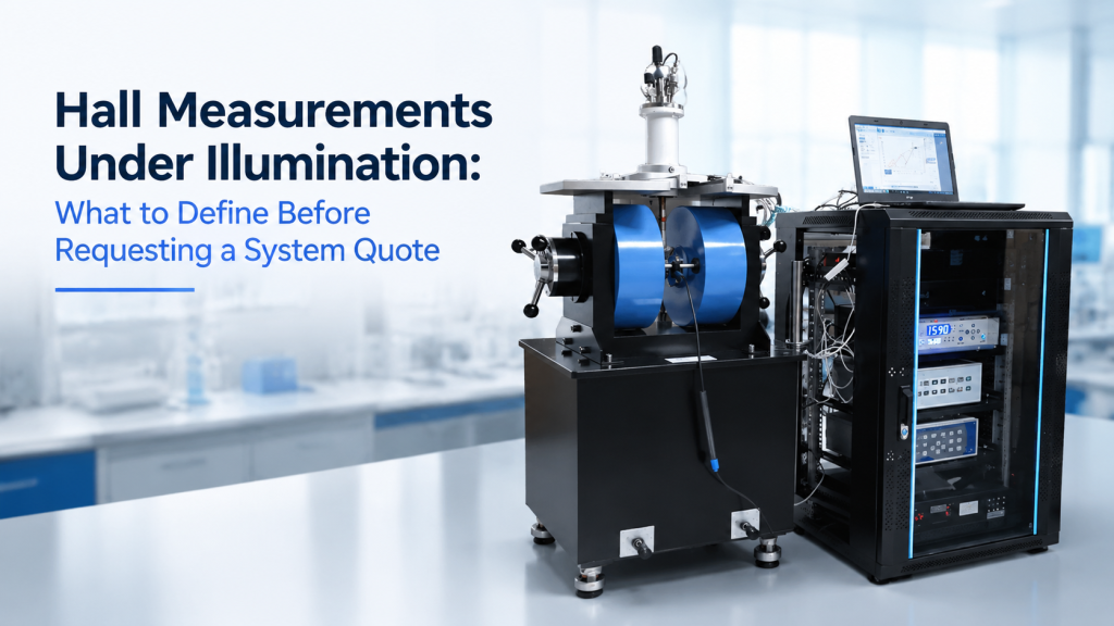
Standard Hall measurements are usually discussed in terms of:
- Magnetic field
- sample current
- Hall voltage
- carrier concentration
- carrier mobility
- sample geometry
- temperature
But once illumination is added, the measurement becomes more complex.
The buyer must also define:
- Light wavelength
- optical power or irradiance
- illuminated area
- light uniformity
- front-side or back-side illumination
- continuous or pulsed operation
- dark-to-light timing
- optical access inside the magnet or cryostat
- sample heating
- reference photodetector
- shielding from room light
- data synchronization
Without these details, two suppliers may quote very different systems while both describing them as suitable for Hall measurements under illumination.
For semiconductor, photovoltaic, perovskite, photoconductive, optoelectronic, and low-temperature material research, illumination is not simply an accessory added beside a Hall system. It changes the experimental condition and may change the interpretation of carrier concentration and mobility.
This article explains what buyers should define before requesting a quotation for a Hall Effect Measurement System with optical or cryogenic integration.
1. Why Perform Hall Measurements Under Illumination?
Hall measurements are widely used to determine semiconductor carrier type, carrier concentration, resistivity, and Hall mobility. NIST describes Hall measurements as an important semiconductor characterization method and notes that carrier density and mobility are determined through combined Hall and resistivity measurements.
Adding illumination can help researchers study:
- Photogenerated charge carriers
- photoconductivity
- carrier trapping
- recombination
- persistent photoconductivity
- illumination-dependent mobility
- minority-carrier behavior
- defects and trap states
- photovoltaic materials
- photodetectors
- light-sensitive thin films
Research published in Nature has demonstrated that combining controlled illumination with magnetotransport measurements can reveal carrier information beyond conventional dark Hall measurements, including separate electron and hole transport behavior under defined light-injection conditions.
The measurement can be powerful.
But only when the illumination condition is defined and controlled.
2. “Under Illumination” Is Not a Complete Specification
A weak RFQ may say:
“We need a Hall system with illumination.”
That does not tell the supplier enough.
Illumination could mean:
- One visible LED
- a broadband white-light source
- monochromatic light
- ultraviolet exposure
- near-infrared illumination
- simulated sunlight
- pulsed laser excitation
- modulated light for lock-in detection
- light delivered through a cryostat window
- light delivered through an optical fiber
- uniform full-sample exposure
- a focused micro-spot
These configurations require different hardware.
Before asking for a quotation, buyers should define what the light must do to the sample.
3. Start with the Scientific Objective
The optical configuration should follow the scientific question.
Possible objectives include:
- Comparing dark and illuminated Hall properties
- measuring mobility versus light intensity
- identifying majority and minority carrier behavior
- studying photo-doping
- measuring persistent photoconductivity
- observing trap filling
- testing a photodetector under operating conditions
- reproducing solar-cell illumination
- studying wavelength-dependent transport
- measuring low-temperature photo-Hall behavior
- performing transient measurements after light switching
A supplier cannot select the right light source, window, detector, timing method, or sample holder without knowing the objective.
4. Define Dark, Light, and Recovery States
Hall measurements under illumination often involve more than two simple conditions.
A complete sequence may include:
- Dark stabilization
- dark Hall measurement
- illumination start
- light-soaking period
- illuminated Hall measurement
- illumination stop
- dark recovery period
- repeated measurement
- another light intensity or wavelength
The buyer should state whether the material returns quickly to its original dark condition.
Some materials may retain illumination-induced changes after the light is removed.
If recovery is slow, the measurement order can affect the result.
5. Specify the Required Wavelength
The light-source wavelength is one of the first specifications to define.
Possible ranges include:
- Ultraviolet
- visible
- near-infrared
- short-wave infrared
- broadband white light
- simulated solar spectrum
The required wavelength may depend on:
- Material bandgap
- absorption depth
- defect state
- device structure
- substrate transparency
- electrode transparency
- cryostat window transmission
- intended application
Do not request only “LED illumination.”
State the wavelength or useful spectral range.
Better Specification
“Continuous 530 nm LED illumination with adjustable irradiance.”
Better Broadband Specification
“Broadband illumination approximating the solar spectrum from 400 to 1,100 nm.”
6. Single Wavelength or Multiple Wavelengths?
Some laboratories need only one illumination condition.
Others need to compare several wavelengths.
A multi-wavelength system may use:
- Exchangeable LEDs
- LED array
- filter wheel
- monochromator
- broadband lamp with filters
- tunable laser
- fiber-coupled sources
Buyers should define:
- Number of wavelengths
- exact wavelengths or wavelength range
- required bandwidth
- whether switching must be manual or automated
- whether optical power must remain comparable between wavelengths
- whether software must record the active wavelength
Adding future wavelength capability later may require another light source, feedthrough, optical path, or control interface.
7. Optical Power and Irradiance Are Not the Same
A light source may be described by total optical power.
But the sample responds to the power delivered over the illuminated area.
Buyers should distinguish between:
- Source output power
- power reaching the sample
- irradiance at the sample
- photon flux
- absorbed optical power
- generation rate
For example, 100 mW spread over a large area is not equivalent to 100 mW focused onto a small spot.
The quotation should state where the optical quantity is defined:
- At the light-source output
- at the fiber output
- before the cryostat window
- after the cryostat window
- at the sample plane
8. Define the Required Intensity Range
A useful illumination system may need adjustable intensity.
The buyer should state:
- Minimum irradiance
- maximum irradiance
- adjustment method
- adjustment resolution
- intensity stability
- required number of setpoints
- whether logarithmic intensity sweeps are needed
- whether one-sun-equivalent testing is required
- whether very low injection conditions are important
Research methods combining illumination and Hall measurements may analyze transport properties as a function of controlled carrier-injection or light-generation conditions, so the light level should be measured rather than described only as “low,” “medium,” or “high.”
9. Define How Light Intensity Will Be Verified
The system may need a calibrated:
- Photodiode
- optical power meter
- irradiance sensor
- reference solar cell
- spectrometer
- integrating-sphere detector
The buyer should ask:
- Is optical power measured at the sample plane?
- Is the detector calibrated for the selected wavelength?
- Can the detector fit inside the magnet or cryostat?
- Is measurement performed before the sample is installed?
- Is a correction applied for cryostat-window transmission?
- Is intensity logged during the Hall measurement?
- Is the reference detector included?
A light-source display is not always proof of the irradiance reaching the sample.
10. Illumination Area Must Match the Sample
Define whether the light should illuminate:
- The complete Hall sample
- only the active layer
- the region between voltage contacts
- a device channel
- one local point
- several devices on one substrate
- the entire sample holder
The required beam size should include:
- Sample dimensions
- active region
- contact location
- positioning tolerance
- beam movement
- alignment margin
A 2 mm optical spot may be unsuitable for a 10 mm van der Pauw sample if uniform full-sample illumination is required.
11. Uniform Illumination May Be More Important Than High Power
Uneven illumination can create nonuniform conductivity.
This may affect:
- Current distribution
- Hall voltage
- longitudinal voltage
- local carrier density
- apparent mobility
- repeatability after remounting
If uniform exposure is required, define:
- Illuminated area
- intensity-uniformity tolerance
- test plane
- measurement grid
- distance from source to sample
- acceptable edge falloff
- diffuser or homogenizer requirement
“Uniform light” should be a measurable specification, not a visual judgment.
12. Focused Illumination Is a Different System
A focused spot may be useful for:
- Local defect studies
- microdevices
- spatially resolved measurements
- patterned Hall bars
- small photodetectors
- local photo-doping
But focused illumination may require:
- Microscope objective
- focusing lens
- XYZ optical adjustment
- camera
- beam profiler
- optical table
- smaller cryostat window
- position calibration
- more precise sample holder
A full-area LED and a focused laser spot are not interchangeable configurations.
13. Front-Side or Back-Side Illumination?
The optical path should be defined relative to the sample.
Front-Side Illumination
Light enters from the side containing the active layer or electrical contacts.
Possible issues include:
- Contact shadowing
- probe obstruction
- wire-bond shadowing
- reflection from electrodes
- limited space around the sample holder
Back-Side Illumination
Light passes through the substrate.
Possible issues include:
- Substrate absorption
- wavelength-dependent transmission
- rough backside surface
- sample-holder obstruction
- different absorption profile
The supplier needs to know which side must remain optically accessible.
14. Define the Angle of Incidence
Illumination may be:
- Normal to the sample
- angled
- parallel to the magnetic field
- perpendicular to the magnetic field
- through an optical window beside the poles
- delivered through a fiber close to the sample
Angle matters when:
- Optical absorption is polarization-dependent
- contacts block the beam
- the magnet pole gap is narrow
- a cryostat window is used
- reflected light must be collected
- the sample is rotated
A drawing is often more useful than a paragraph.
15. Light Polarization May Matter
Some experiments require:
- Unpolarized light
- linear polarization
- circular polarization
- variable polarization
- known polarization relative to sample axes
This may add:
- Polarizer
- wave plate
- polarization rotator
- motorized optical mount
- calibration procedure
- larger optical-access requirement
Do not add polarization hardware by default.
Specify it only when it supports the actual scientific objective.
16. Continuous, Modulated, or Pulsed Illumination?
The illumination timing can strongly affect system architecture.
Continuous Illumination
Suitable for steady-state light-dependent measurements.
Modulated Illumination
Useful when the optical signal is switched or chopped at a defined frequency.
It may support:
- Synchronous detection
- background rejection
- lock-in measurements
- dark/light comparison
- response-time studies
Pulsed Illumination
May require:
- Trigger synchronization
- fast acquisition
- pulse-energy measurement
- detector bandwidth
- timing electronics
- oscilloscope or digitizer
- careful thermal and electrical analysis
A standard Hall system designed for slow DC measurements may not capture fast pulsed responses.
17. Define the Required Time Resolution
Buyers should state whether they need:
- Steady-state measurement only
- second-level light switching
- millisecond response
- microsecond response
- faster transient measurement
The required time resolution affects:
- Voltmeter or source-measure unit
- switching matrix
- magnetic-field operation
- illumination trigger
- data-acquisition rate
- software
- synchronization
- noise level
Fast acquisition and high precision often require trade-offs.
18. Light-Soaking Time Must Be Defined
Some samples do not reach a stable illuminated condition immediately.
The procedure may require:
- 10 seconds of illumination
- several minutes of light soaking
- a fixed stabilization criterion
- measurement during the transient
- measurement only after stabilization
The system software may need to:
- Start illumination
- wait for a defined time
- monitor longitudinal resistance
- begin Hall acquisition after stabilization
- record elapsed time
- stop illumination
- track recovery
Without defined timing, measurements from different laboratories may not be comparable.
19. Define Whether the Magnetic Field Is DC or Alternating
The magnetic-field method may be:
- Static positive and negative field
- swept DC field
- bipolar field reversal
- low-frequency AC field
- fixed-field measurement
- multi-point field sequence
NIST’s conventional Hall procedure uses measurements at positive and negative magnetic field to reduce the effect of offset voltages caused by sample geometry, contact placement, and temperature nonuniformity.
When illumination is added, the buyer should define whether light remains constant during field reversal or is synchronized with each field condition.
20. Coordinate Light Switching with Field Reversal
Possible measurement sequences include:
Sequence A
- Dark at +B
- dark at −B
- light at +B
- light at −B
Sequence B
- Dark and light measurements at +B
- reverse field
- repeat dark and light measurements at −B
Sequence C
- Continuous field reversal
- modulated illumination
- synchronous signal detection
Each sequence may experience different:
- Drift
- thermal history
- light-soaking history
- recovery behavior
- offset cancellation
- total measurement time
The system quote should be based on the intended workflow.
21. Sample Current Must Be Defined Under Illumination
Illumination can change sample resistance significantly.
A current suitable in the dark may produce different voltage or heating under illumination.
Buyers should define:
- Current range
- constant-current or constant-voltage operation
- current reversal
- compliance voltage
- maximum sample power
- acceptable self-heating
- automatic current adjustment
- current used for each light condition
A current sweep may be useful for checking whether the Hall result depends on sample heating or non-ohmic contacts.
22. Avoid Mixing Optical Heating with Electrical Heating
The sample may be heated by:
- Illumination
- sample current
- heater power
- poor thermal contact
- infrared radiation
- cryostat window radiation
This matters because Hall mobility, carrier concentration, and resistance can depend on temperature.
The system should distinguish between:
- True photo-induced change
- temperature-induced change
- combined photo-thermal effect
Useful controls may include:
- Temperature sensor close to the sample
- dark measurement at the same temperature
- optical power sweep
- low-current verification
- waiting for thermal stabilization
- monitoring heater output
23. Sample Temperature Must Be Measured Near the Sample
A cryostat cold head may be at one temperature while the illuminated sample is warmer.
Possible causes include:
- Poor thermal contact
- optical heating
- heater operation
- wiring heat leak
- vacuum radiation
- weak sample-holder link
For low-temperature Hall measurements under illumination, the buyer should define:
- Sensor location
- sample-stage temperature
- acceptable sample-to-sensor temperature difference
- temperature stability
- illumination-induced temperature rise
- whether light intensity must be reduced at low temperature
A controller reading alone may not fully describe the sample temperature.
24. Room Temperature or Cryogenic Operation?
The optical Hall configuration is much simpler at room temperature.
Cryogenic operation adds:
- Optical windows
- radiation shields
- internal optical alignment
- thermal anchoring
- vacuum feedthroughs
- window transmission
- condensation prevention
- additional sample heating
- limited working space
- longer stabilization time
The quotation should state the complete temperature range.
Do not write only “low temperature.”
Specify, for example:
- 80–370 K
- 10–300 K
- 4.2–300 K
- another defined range
25. Cryostat Window Material Must Match the Wavelength
Window material determines which wavelengths can reach the sample.
Possible materials include:
- Fused silica
- quartz
- sapphire
- calcium fluoride
- zinc selenide
- other optical materials
The buyer should define:
- Wavelength range
- window diameter
- clear aperture
- coating requirement
- number of windows
- window angle
- transmission data
- vacuum and temperature rating
A window suitable for visible illumination may not be suitable for infrared or ultraviolet use.
26. Window Transmission Must Be Included in Power Calibration
Optical power measured before the cryostat window may be higher than power reaching the sample.
Losses may come from:
- Reflection
- absorption
- coatings
- contamination
- multiple windows
- radiation shields
- lenses
- fiber coupling
The quotation should clarify whether the specified irradiance is:
- Before the window
- after the window
- estimated at the sample
- measured directly at the sample plane
This is critical when comparing results across wavelengths.
27. Free-Space or Fiber-Coupled Illumination?
Free-Space Illumination
Advantages:
- Larger beam possible
- easier high-power delivery
- flexible lens selection
- easier polarization control
Challenges:
- Alignment
- open optical path
- vibration sensitivity
- magnet or cryostat obstruction
- greater space requirement
Fiber-Coupled Illumination
Advantages:
- Compact delivery
- easier routing
- source can remain outside the magnet area
- simpler source exchange
- reduced open-beam exposure
Challenges:
- Coupling loss
- limited wavelength range
- output divergence
- fiber movement
- cryogenic feedthrough complexity
- power calibration
The supplier should know which architecture the laboratory prefers.
28. Light Source Location Affects Maintenance
The source may be:
- Integrated close to the sample
- outside the magnet
- outside the cryostat
- mounted on an optical table
- connected through a fiber
- installed in a separate light-tight enclosure
A locally accessible source is easier to replace.
An internal source may provide compact illumination but can add heat, wiring, magnetic material, and maintenance difficulty.
For cryogenic systems, keeping the active light source at room temperature and delivering light optically is often easier to service.
29. The Sample Holder Must Support Both Electrical and Optical Access
A Hall sample holder under illumination may need to provide:
- Four or more electrical contacts
- stable sample current
- low-noise Hall voltage leads
- optical aperture
- temperature sensor
- optional heater
- thermal contact
- non-magnetic construction
- defined sample orientation
- light shielding around inactive areas
The holder should not:
- Block the beam
- create strong reflections
- shadow part of the sample
- place contacts in the optical path
- pull wires across the active area
- shift the sample away from the magnetic center
The optical and electrical design must be developed together.
30. Contact Material May Affect Optical Testing
Electrical contacts may:
- Reflect light
- absorb light
- shadow the active layer
- heat locally
- degrade under UV exposure
- change after thermal cycling
- create photoelectric artifacts
The buyer should provide:
- Sample drawing
- contact material
- contact size
- contact position
- active-area location
- layer structure
- illumination side
This helps the supplier design an appropriate sample holder and optical path.
31. Van der Pauw and Hall-Bar Samples Need Different Fixtures
Van der Pauw Samples
Usually require contacts around the sample perimeter.
Optical design should consider:
- Full-area exposure
- corner contacts
- wire placement
- sample shape
- thickness
Hall-Bar Samples
Have a defined current channel and transverse voltage contacts.
Optical design should consider:
- Channel illumination
- contact shadowing
- spot alignment
- device orientation
- possible local measurement
A universal holder may not support both formats equally well.
32. Transparent and Opaque Substrates Change the Optical Path
For transparent substrates, backside illumination may be practical.
For opaque substrates, front-side or angled illumination may be required.
The supplier should know:
- Substrate material
- substrate thickness
- transmission range
- reflective layers
- metal electrode coverage
- sample encapsulation
- active-layer position
Without this information, optical access may be physically available but scientifically ineffective.
33. Encapsulation and Atmosphere May Matter
Some light-sensitive semiconductor materials may degrade in:
- Oxygen
- humidity
- vacuum
- strong illumination
- elevated temperature
The sample may require:
- Encapsulation
- inert atmosphere
- glovebox transfer
- vacuum-compatible holder
- controlled gas
- sealed sample cell
- limited light exposure
In the Nature Communications CLIMAT study, encapsulation was used for perovskite samples to prevent atmospheric degradation, illustrating why material stability and environment must be considered together with the Hall and optical setup.
34. Define Vacuum or Controlled-Gas Requirements
Possible sample environments include:
- Air
- vacuum
- nitrogen
- argon
- controlled oxygen
- another process gas
The buyer should specify:
- Pressure range
- gas type
- gas-flow requirement
- whether illumination occurs through a window
- whether electrical feedthroughs are required
- whether the sample must be exchanged under inert conditions
- whether gas changes during measurement
A standard optical Hall holder does not automatically provide a controlled atmosphere.
35. Room Light Must Be Controlled
Ambient light can affect photosensitive samples.
A system may need:
- Light-tight enclosure
- black covers
- covered cryostat window
- controlled dark box
- status indicator
- shutter
- defined dark-adaptation time
- low-light sample loading
“Dark measurement” should mean a defined condition.
A room with ceiling lights switched off may still contain monitor light, indicator LEDs, or daylight.
36. Reflections and Stray Light Need Attention
Stray light may reach:
- Electrical contacts
- reference detector
- nearby samples
- temperature sensor
- cryostat walls
- field probe
Reflections can create nonuniform illumination or optical heating.
Possible controls include:
- Baffles
- blackened surfaces
- apertures
- diffusers
- beam stops
- light-tight covers
- anti-reflection coatings
These are especially important for small samples and focused beams.
37. Light Sources Can Introduce Electrical Noise
LED drivers, laser controllers, shutters, and modulation electronics may introduce:
- Switching noise
- ground loops
- electromagnetic interference
- trigger noise
- cable coupling
- power-line interference
This can be serious when Hall voltages are in the microvolt range. NIST notes that Hall voltages may be very small and that contact asymmetry and temperature nonuniformity can create larger offset voltages that must be controlled through careful measurement procedures.
The optical source and driver should therefore be evaluated as part of the low-noise electrical system.
38. Separate Optical Power Cables from Hall Signal Leads
Good cable planning may include:
- Separate routing for LED or laser drivers
- twisted sample-current leads
- shielded Hall voltage leads
- minimized cable loops
- stable grounding
- mechanical strain relief
- optical-source grounding review
- separation from magnet power cables
- low-noise feedthroughs
The lighting system should not reduce the quality of the Hall measurement it is intended to support.
39. Define the Data That Must Be Recorded
A useful illuminated Hall dataset may include:
- Sample ID
- sample geometry
- thickness
- temperature
- magnetic field
- sample current
- light wavelength
- optical power
- irradiance
- illuminated area
- light state
- light-soaking time
- Hall voltage
- longitudinal voltage
- sheet resistance
- carrier type
- carrier concentration
- Hall mobility
- measurement timestamp
- recovery time
- operator
- software version
If these conditions are not stored with the results, later comparison becomes difficult.
40. Do Not Apply a Simple Single-Carrier Model Automatically
In a conventional single-majority-carrier Hall measurement, carrier concentration and mobility may be calculated from Hall and resistivity data using established relationships.
Under illumination, however, both electron and hole populations may contribute to electrical transport.
Depending on the material and injection condition, a simple single-carrier interpretation may become incomplete or misleading. Research on photo-Hall and light-induced magnetotransport methods has specifically addressed the need to resolve electron and hole contributions under controlled illumination.
Buyers should clarify whether they need:
- Conventional light-dependent Hall results
- apparent Hall mobility and carrier concentration
- two-carrier analysis
- minority-carrier information
- research-grade photo-Hall analysis
- raw data only for independent modelling
The required analysis software can significantly change the quotation.
41. Apparent Carrier Concentration Should Be Reported Carefully
A software package may calculate a carrier concentration automatically.
But under illumination, the result may represent an effective or apparent value based on the selected model.
The report should state:
- Calculation model
- assumptions
- carrier types considered
- thickness used
- background subtraction
- sign convention
- whether conductivity is measured simultaneously
- whether the result is dark, illuminated, or differential
Software should not hide the physical assumptions behind one final number.
42. Lock-In Detection May Help Weak Signals
Low-mobility or high-resistance materials may generate weak Hall signals.
Possible strategies include:
- Magnetic-field reversal
- current reversal
- AC magnetic field
- modulated current
- modulated illumination
- lock-in amplifier
- signal averaging
- longer integration time
The Nature Communications study used an AC magnetic field and lock-in amplification for low-signal semiconductor measurements, demonstrating one possible research architecture rather than a universal requirement for every illuminated Hall system.
The buyer should specify whether conventional DC measurement is sufficient or synchronous detection is required.
43. Light Modulation Frequency Must Match the Material
A modulation frequency that is too high may not allow the sample response to reach equilibrium.
A frequency that is too low may increase measurement time and expose the signal to drift.
Selection depends on:
- Carrier lifetime
- trap dynamics
- thermal response
- persistent photoconductivity
- measurement bandwidth
- lock-in time constant
- light-source switching speed
The supplier needs either the expected response time or the required modulation range.
44. Reference Photodetector Placement
A reference detector may be used to monitor illumination stability.
Possible locations include:
- Before the sample
- beside the sample
- behind the sample
- at a beam splitter
- outside the cryostat window
- temporarily at the sample plane
Each location measures a different optical condition.
The system should state whether the reference detector measures:
- Source stability
- incident power
- transmitted power
- reflected power
- approximate sample irradiance
This is particularly important for long measurements.
45. Optical Stability Should Be Included in Long Tests
For long-duration illuminated Hall measurements, monitor whether light intensity drifts with:
- Source warm-up
- LED temperature
- laser power
- fiber coupling
- chiller operation
- window contamination
- alignment movement
- power supply drift
The optical source may require a warm-up period before the measurement begins.
If intensity changes, the carrier response may change even if the Hall system is stable.
46. Define Whether Automated Optical Control Is Required
Possible automation functions include:
- Light on/off
- intensity control
- wavelength switching
- shutter control
- pulse triggering
- modulation frequency
- detector readback
- light-soaking timer
- dark recovery timer
- synchronization with field and current
- data logging
Manual control may be sufficient for exploratory research.
Automated control is more useful when measurements involve many temperatures, fields, wavelengths, or light levels.
47. Control Interface Requirements
The optical subsystem may need:
- USB
- Ethernet
- RS-232
- analog control
- TTL trigger
- SCPI
- Python API
- LabVIEW support
- external modulation input
The buyer should ask:
- Can the Hall software control the light source directly?
- Is a separate program required?
- Can optical conditions be stored in the Hall data file?
- Can trigger signals be shared?
- Is source readback available?
- What happens if communication is lost?
A programmable source is not automatically integrated with the Hall measurement workflow.
48. Safety Requirements for Optical Sources
Depending on the light source, the system may require:
- Laser enclosure
- safety interlock
- protective eyewear
- beam stop
- warning label
- key switch
- emergency stop
- covered fiber connector
- UV shielding
- restricted access
An LED system and a high-power laser system have very different safety requirements.
Optical safety should be included in the project boundary before PO.
49. What Should Be Included in FAT?
Factory Acceptance Testing for an illuminated Hall system may include:
Electrical Tests
- Contact check
- dark resistance
- positive and negative field
- current reversal
- Hall voltage
- repeatability
Optical Tests
- Wavelength confirmation
- output power
- irradiance at sample plane
- beam size
- illumination uniformity
- light on/off control
- source stability
- shutter or modulation test
Integrated Tests
- Dark Hall measurement
- illuminated Hall measurement
- dark recovery measurement
- temperature monitoring
- field and light synchronization
- data export
- reference-sample measurement
The exact FAT scope should match the quotation.
50. FAT Photos and Raw Data to Request
Buyers should request:
- Sample mounting photos
- optical path photos
- cryostat-window photos
- beam-position photos
- reference detector location
- light-source model and serial number
- optical power calibration record
- magnetic-field verification data
- raw Hall voltage data
- raw longitudinal voltage data
- dark/light timing record
- temperature log
- software screenshots
- exported CSV or native data files
A short video showing the light turning on is not enough.
51. What Must Be Rechecked During SAT?
After delivery, Site Acceptance Testing may need to verify:
- Optical alignment
- beam position
- irradiance at sample
- cryostat-window transmission
- ambient-light shielding
- sample-holder position
- electrical noise
- grounding
- source control
- temperature rise
- dark/light repeatability
- data synchronization
Overseas transport and reassembly can change optical alignment even when the magnet and electrical system remain correct.
52. Questions Buyers Should Answer Before Requesting a Quote
Sample Information
- Material:
- substrate:
- dimensions:
- thickness:
- Hall-bar or van der Pauw:
- contact material:
- active-area location:
- transparent or opaque:
- encapsulation required:
Electrical Requirement
- Sample current range:
- resistance range:
- expected Hall voltage:
- current reversal:
- field reversal:
- two-wire or four-wire resistance:
- gate or bias lines:
- low-current requirement:
Magnetic Requirement
- Maximum field:
- bipolar field:
- field direction:
- sweep mode:
- field stability:
- uniformity region:
- DC or AC field:
Optical Requirement
- Wavelength:
- bandwidth:
- irradiance range:
- illuminated area:
- uniformity:
- front-side or back-side:
- continuous, modulated, or pulsed:
- polarization:
- light-soaking time:
- reference detector:
Temperature and Environment
- Room temperature or cryogenic:
- temperature range:
- vacuum or gas:
- window material:
- temperature stability:
- acceptable optical heating:
- sample-atmosphere requirement:
Automation
- Automated light control:
- wavelength switching:
- intensity sweep:
- trigger:
- lock-in:
- API:
- data logging:
- report format:
53. Better RFQ Language
Weak RFQ
“We need a Hall Effect Measurement System with illumination.”
Better RFQ
“We require a Hall Effect Measurement System for dark and illuminated measurements of semiconductor thin films. Samples are approximately 10 mm × 10 mm and use a four-contact van der Pauw configuration. The system should provide bipolar magnetic field up to ±1 T, sample-current reversal, and measurements from 80 K to 350 K.
Illumination should be delivered through a cryostat window using interchangeable 530 nm, 660 nm, and 850 nm LED sources. The irradiance should be adjustable and measured at the sample plane. The full sample should be illuminated with defined spatial uniformity. Software should automate dark stabilization, light soaking, illuminated Hall measurement, light-off recovery, field reversal, and data export.
Please specify optical power range, beam size, window transmission, temperature rise under maximum illumination, sample-holder design, reference detector, control interfaces, calculation model, and FAT scope.”
This gives suppliers a measurable project.
54. When a Standard Hall System May Be Enough
A standard Hall system with a simple illumination accessory may be suitable when:
- Room-temperature testing is sufficient.
- one LED wavelength is required.
- steady-state illumination is used.
- the sample is easy to access.
- intensity accuracy is moderate.
- conventional single-carrier analysis is acceptable.
- manual light control is acceptable.
- no vacuum or cryostat is required.
Do not over-design the system when the experiment is simple.
55. When a Custom System Is More Appropriate
Customization is more likely when the project requires:
- Cryogenic operation
- several wavelengths
- calibrated irradiance
- full-sample uniformity
- focused micro-spot
- optical modulation
- pulsed measurement
- lock-in detection
- controlled atmosphere
- two-carrier analysis
- automated dark/light sequences
- optical polarization
- multiple samples
- optical and magnetic synchronization
These requirements affect more than the light source.
They affect the magnet, sample holder, cryostat, wiring, software, and acceptance procedure.
56. Common Buyer Mistakes
Mistake 1: Asking Only for “Illumination”
Wavelength, intensity, area, timing, and geometry must be defined.
Mistake 2: Specifying Source Power but Not Sample Irradiance
Optical losses and beam size affect the power reaching the sample.
Mistake 3: Forgetting Sample Heating
Illumination may change temperature as well as carrier population.
Mistake 4: Ignoring Window Transmission
Cryostat windows may not transmit the required wavelength efficiently.
Mistake 5: Using One-Carrier Analysis Without Review
Electrons and holes may both contribute under illumination.
Mistake 6: Ignoring Dark Recovery
Some materials may not immediately return to their initial state.
Mistake 7: Forgetting Light Uniformity
Uneven illumination can create nonuniform current flow.
Mistake 8: Ignoring Electrical Noise from the Light Driver
Optical control electronics can disturb low-level Hall signals.
Mistake 9: Not Defining the Timing Sequence
Dark, light-soaking, measurement, and recovery stages should be reproducible.
Mistake 10: Testing Only the Optical Source During FAT
The light and Hall measurement must be tested together.
57. How Cryomagtech Supports Hall Measurements Under Illumination
Cryomagtech supplies Hall Effect Measurement Systems, electromagnets, bipolar excitation power supplies, cryogenic temperature controllers, temperature monitors, cryogenic sensors, optical-access cryostats, and custom Magnet & Field Systems.
For Hall measurements under illumination, we help evaluate:
- Hall-bar and van der Pauw sample geometry
- magnetic field range and reversal
- sample-current range
- dark and illuminated measurement sequences
- light wavelength and irradiance
- full-area or focused illumination
- optical-access geometry
- cryostat window compatibility
- low-temperature operation
- sample temperature monitoring
- light-soaking and recovery time
- electrical and optical synchronization
- lock-in and low-signal options
- optical control interfaces
- sample-holder and wiring design
- FAT and SAT requirements
- raw-data and calculation boundaries
Hall measurements under illumination should not begin with the question:
“Can you add a light source?”
They should begin with a clearer engineering question:
“What optical, electrical, magnetic, thermal, timing, and analysis conditions must be controlled so that the illuminated Hall result is physically meaningful and repeatable?”
References
- NIST – Hall Effect Measurements Introduction
https://www.nist.gov/pml/nanoscale-device-characterization-division/popular-links/hall-effect/hall-effect-measurements-3 - Nature Communications – Resolving Electron and Hole Transport Properties in Semiconductor Materials by Constant Light-Induced Magneto Transport
https://www.nature.com/articles/s41467-023-44418-1 - Nature – Carrier-Resolved Photo-Hall Effect
https://doi.org/10.1038/s41586-019-1632-2
Key Takeaways
- Hall measurements under illumination require optical, electrical, magnetic, thermal, and timing specifications.
- Buyers should define wavelength, irradiance, illuminated area, uniformity, incidence direction, and light-source stability.
- Optical power at the source is not the same as irradiance reaching the sample.
- Dark adaptation, light-soaking, illuminated measurement, and recovery time should be defined as a repeatable sequence.
- Illumination may change both carrier transport and sample temperature.
- Cryogenic systems require compatible windows, thermal management, sample-stage sensing, and optical-access planning.
- Light drivers, shutters, and modulation electronics can introduce noise into weak Hall signals.
- Under illumination, electrons and holes may both contribute, so conventional single-carrier calculations should not always be accepted without review.
- FAT should test the integrated dark-and-light Hall workflow, not only the light source.
- A complete quote requires sample drawings, electrical ranges, field requirements, optical conditions, temperature range, control interfaces, and acceptance scope.
For illuminated Hall system procurement, the key question is not only:
“Does the system include optical access?”
The better question is:
“Can it deliver and measure a controlled illumination condition at the sample while preserving accurate, low-noise, temperature-aware Hall measurements?”