Designing a magnetic field system starts with a simple question:
How much current and power are actually required to reach the target field?
This article walks through the full calculation path—from target magnetic field to coil current, resistance, power dissipation, and driver margin—with practical engineering considerations.
1. Start with the Target Magnetic Field
Most specifications begin with a target field, typically expressed as:
- µT (Earth-field-level experiments)
- mT (sensor calibration, material studies)
Define clearly:
- Required field amplitude
- DC or AC operation
- Continuous or intermittent use
This step sets all downstream requirements.
2. The B–I Coefficient: Field per Ampere
The key parameter linking field and current is the B–I coefficient:
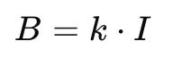
Where:
- B = magnetic field (T)
- I = coil current (A)
- k = field constant (T/A or mT/A)
For Helmholtz coils, k depends on:
- Coil radius
- Number of turns
- Coil geometry and spacing
Manufacturers usually provide this coefficient directly.
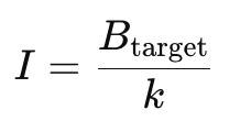
3. Calculating Required Coil Current
Once k is known:
Example:
- Target field: 1 mT
- Coil constant: 0.5 mT/A
Required current:
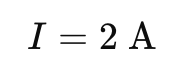
This value must be achievable continuously, not just peak.
4. Coil Resistance and Temperature Rise
Current alone is not enough.
Coil resistance determines heat generation.
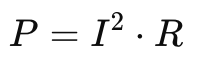
Where:
- P = power dissipation (W)
- R = coil resistance (Ω)
Resistance increases with temperature, which causes:
- Additional heating
- Drift in magnetic field
- Long-term instability
Thermal design becomes critical for continuous operation.
5. Estimating Power Dissipation
Power dissipation defines:
- Cooling requirements
- Duty cycle limits
- System lifetime
Example:
- Current: 2 A
- Resistance: 5 Ω
This heat must be removed safely to maintain stability.
6. Driver and Power Supply Margin
Never select a driver at the exact calculated limit.
Recommended margins:
- Current headroom: ≥ 20–30%
- Voltage headroom: ≥ 20%
- Power headroom: ≥ 30%
Margins ensure:
- Stable long-term operation
- Lower noise and ripple
- Reduced thermal stress
7. Long-Term Stability and Drift
For long measurements:
- Copper resistance increases with temperature
- Field drifts with current instability
- Noise appears as field fluctuation
A precision current driver with low noise and low drift is essential, especially for µT-level fields.
8. System-Level Design Approach
The safest approach is to design the system as a whole:
- Coil geometry
- Thermal behavior
- Driver resolution and stability
Cryomagtech supports integrated solutions including:
- Helmholtz Coils
- Electromagnets
- Matching drivers and power supplies
👉 Product link placeholder: Helmholtz Coil & Driver System Solutions
References
- Wikipedia – Helmholtz coil fundamentals
https://en.wikipedia.org/wiki/Helmholtz_coil - IEEE – Magnetic field generation and control
https://ieeexplore.ieee.org/
Key Takeaways
- Field targets define current requirements
- Current defines power and thermal behavior
- Driver margin determines stability and lifetime
Skipping any step leads to undersized systems or unstable results.