
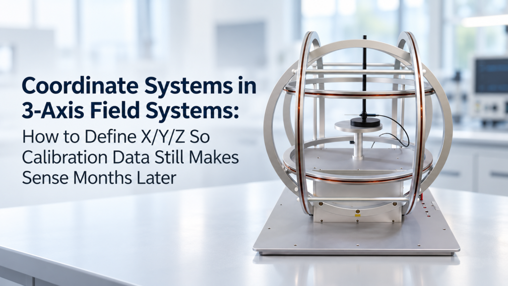
A 3-axis magnetic field system can generate precise X, Y, and Z fields.
But there is a surprisingly common problem:
What exactly do X, Y, and Z mean?
For magnetometer, IMU, electronic compass, AHRS, and three-axis magnetic sensor calibration, writing “+50 µT on X” is not enough.
You also need to know:
- Which physical direction is +X?
- Where is the coordinate origin?
- Is the system right-handed or left-handed?
- Is the X-axis defined by the coil, the fixture, or the sensor?
- What does positive rotation around Z mean?
- Was the DUT installed in the same orientation during the next calibration?
- How are sensor coordinates transformed into the laboratory coordinate frame?
Without these definitions, calibration data may look perfectly valid today and become almost impossible to interpret six months later.
This article explains how to define and document coordinate systems in a 3-axis field system so calibration results remain reproducible, comparable, and traceable.
1. X, Y, and Z Are Labels Until You Define the Reference Frame
The first mistake is assuming that “X-axis” has a universal physical meaning.
It does not.
One engineer may define:
- +X = forward
- +Y = left
- +Z = upward
Another may use:
- +X = right
- +Y = forward
- +Z = upward
A sensor manufacturer may define its axes according to the PCB orientation, while the test laboratory defines the Helmholtz coil axes according to the test bench.
All three conventions can be internally correct.
The problem begins when data moves between them.
A coordinate frame needs more than three letters
At minimum, every calibration coordinate system should define:
- Origin
- Positive X direction
- Positive Y direction
- Positive Z direction
- Coordinate-system handedness
- Positive rotation convention
NASA/JPL documentation provides a useful general principle: reference frames are defined by mutually related axes, and its SPICE conventions use right-handed frames in which X × Y = Z. Positive angular direction is then defined consistently using the right-hand rule. NAIF
This principle is just as valuable on a laboratory calibration bench as it is in spacecraft navigation.
2. A 3-Axis Calibration Setup Usually Has More Than One Coordinate System
For serious IMU or magnetometer calibration, thinking in terms of only one XYZ frame is often too simplistic.
There may be four different coordinate frames in the same experiment.
Laboratory Frame
This is the fixed reference frame of the test environment.
For example:
- X_L = along the laboratory bench
- Y_L = perpendicular to the bench
- Z_L = vertically upward
The laboratory frame should remain fixed even if the sensor or fixture changes.
Coil Frame
The three orthogonal coil pairs create another coordinate frame:
- X_C = field generated by Coil Pair X
- Y_C = field generated by Coil Pair Y
- Z_C = field generated by Coil Pair Z
Ideally, these three magnetic axes are perfectly orthogonal.
In reality, small mechanical or magnetic misalignments may exist.
Therefore:
coil labels and calibrated field axes should not automatically be treated as mathematically perfect axes.
Fixture Frame
The calibration fixture introduces its own reference system.
For example:
- X_F = along the locating rail
- Y_F = toward the locking screw
- Z_F = normal to the mounting surface
This becomes particularly important when the DUT is repeatedly installed and removed.
DUT or Sensor Frame
Finally, the device under test has its own axes:
- X_S
- Y_S
- Z_S
These may be defined by:
- PCB silkscreen
- Sensor package markings
- Mechanical housing
- Manufacturer documentation
- Internal software convention
A professional calibration procedure should therefore know not only the magnetic field vector, but also which coordinate frame that vector belongs to.
3. Define a Physical Origin — Not Just Axis Directions
Users often document axis directions while forgetting the origin.
That is dangerous in a real 3-axis Helmholtz coil system.
Why the origin matters
The center of the nominal X, Y, and Z coil geometry is usually intended to define the primary working region.
But the actual DUT may be mounted:
- 20 mm above geometric center
- 15 mm forward
- 10 mm to one side
If the fixture changes later, simply saying “sensor located at the coil center” may no longer be precise enough.
A better definition could be:
Origin O_C: intersection of the three calibrated magnetic axes at the nominal center of the uniform field region.
Then document DUT position relative to it:
- ΔX = +5.0 mm
- ΔY = −2.0 mm
- ΔZ = +8.0 mm
NIST guidance on coordinate-frame registration highlights the broader metrology principle involved here: measurements may exist in different local coordinate frames, and meaningful comparison requires establishing the transformation between those frames. NIST
The same logic applies directly to sensor calibration.
4. Use a Right-Handed XYZ Coordinate System Unless There Is a Strong Reason Not To
For laboratory documentation, the safest default is usually a right-handed Cartesian coordinate system.
A simple definition
Define:
+X × +Y = +Z
Then positive rotation about each axis follows the right-hand rule.
For example, looking from the positive end of an axis toward the origin, the apparent direction of positive rotation depends on the viewing direction—so writing only “clockwise” is risky.
Instead say:
Positive rotation is defined according to the right-hand rule about the positive axis.
This removes ambiguity.
Why “clockwise” creates problems
Imagine a fixture rotating about Z.
One technician stands above the system.
Another looks upward from underneath it.
The same physical rotation appears clockwise to one person and counterclockwise to the other.
The right-hand rule does not have that ambiguity.
5. Never Define Axes Only From the Operator’s Viewpoint
Instructions such as these are weak:
- X is left to right
- Y is front to back
- Z is up and down
Why?
Because “front” depends on where the operator stands.
Months later, the equipment may be:
- Moved to another bench
- Rotated 90°
- Installed inside magnetic shielding
- Integrated into an automated station
- Viewed from another side
Better axis definitions
Use physical references.
For example:
- +X: from the rear panel toward the access opening
- +Y: from the connector side toward the opposite coil
- +Z: vertically upward when the base plate is installed in its nominal orientation
Better still, permanently mark:
- +X
- +Y
- +Z
on the coil frame.
This turns an abstract convention into a physical reference.
6. Separate the Coil Coordinate System from the Sensor Coordinate System
This is one of the most important rules for magnetometer and IMU calibration.
Suppose the field system applies:
B_C = [50, 0, 0] µT
This means +50 µT along the coil’s X-axis.
But if the sensor has been rotated 90°, it may measure that field primarily on its Y channel.
That does not mean the coil or sensor is wrong.
The two coordinate frames are different.
Think in transformations
Conceptually:
B_S = R_SC · B_C
where:
- B_C = magnetic-field vector in the coil frame
- B_S = the same physical magnetic field expressed in the sensor frame
- R_SC = transformation from coil coordinates to sensor coordinates
You do not necessarily need complicated mathematics in everyday production calibration.
But the documentation must preserve enough information to reconstruct this relationship.
7. The Fixture Is Part of the Coordinate System
A calibration fixture is often treated as “just mechanics.”
That is a mistake.
For repeatable vector calibration, the fixture defines orientation.
A good fixture should provide deterministic positioning
Useful features include:
- Locating pins
- Hard reference surfaces
- Keyed mounting
- Mechanical stops
- Clearly defined datum faces
- Asymmetric geometry preventing 180° installation errors
- Engraved axis markings
The goal is simple:
If Technician A installs the sensor today and Technician B installs another unit three months later, both devices should occupy the same coordinate relationship.
Avoid visually symmetric fixtures
A perfectly symmetric fixture can create hidden ambiguity.
If the DUT can be installed in two orientations that look almost identical, one operator may unknowingly rotate it 180°.
Your calibration software may still generate beautiful curves.
They will simply correspond to the wrong orientation.
8. Define the Sensor Datum Explicitly
Do not write:
“Align sensor with coil axes.”
That is too vague.
Instead define what physical feature establishes the DUT frame.
For example:
Sensor Frame Definition
- Origin: geometric center of sensing element
- +X_S: parallel to connector edge, toward connector
- +Y_S: parallel to long PCB edge
- +Z_S: outward normal from PCB component side
If the actual sensitive element is offset from the mechanical center, document that as well.
This distinction can become important when:
- Field uniformity is limited
- Sensor arrays are being tested
- DUT dimensions are large
- Multiple sensors exist on one PCB
9. Rotation Direction Must Be Defined Before Running Multi-Angle Calibration
Many calibration routines rotate the sensor through multiple orientations.
Examples include:
- 0°
- 90°
- 180°
- 270°
or full multi-position calibration.
But an angle is incomplete unless three things are known:
- Rotation axis
- Positive direction
- Starting orientation
Better documentation
Instead of:
Rotate sensor 90°.
Write:
Rotate DUT +90° about +Z_F using the right-hand rule from Position P0.
That statement is reproducible.
Position names can also help
For repetitive production calibration, define positions such as:
- P0
- P1
- P2
- P3
- P4
- P5
Then maintain a position table containing:
- Rotation axis
- Rotation angle
- Fixture orientation
- Expected sensor orientation
- Applied magnetic field
This greatly reduces operator interpretation.
10. Rotation Order Matters
IMU engineers already know this problem, but calibration documentation frequently ignores it.
These two sequences are generally not equivalent:
- Rotate +90° around X
- Rotate +90° around Y
versus:
- Rotate +90° around Y
- Rotate +90° around X
Three-dimensional rotations are order-dependent.
Therefore document the sequence
If Euler angles are used, record:
- Axis sequence
- Angle convention
- Intrinsic or extrinsic rotation
- Degrees or radians
- Positive rotation convention
- Reference frame
Writing only:
Orientation = (90°, 45°, 0°)
is not enough for rigorous traceability.
11. Distinguish Commanded Field from Measured Field
Another subtle problem occurs when the software says:
Bx = 40 µT
What does that mean?
It could mean:
- Requested X-axis field
- Calculated field from coil constant
- Current-command equivalent
- Gaussmeter-measured field
- Background-compensated field
- Total resultant field
These are not necessarily identical.
Recommended data fields
For each calibration point, consider recording:
- Commanded Bx
- Commanded By
- Commanded Bz
- Measured Bx
- Measured By
- Measured Bz
- Coil currents Ix / Iy / Iz
- Ambient field before compensation
- Resultant field magnitude
This makes later investigation much easier.
12. Axis Misalignment Should Be Treated as a Calibration Parameter
An ideal 3-axis Helmholtz coil system has three perfectly orthogonal magnetic axes.
A real system can contain small errors caused by:
- Mechanical assembly tolerances
- Coil geometry
- Fixture alignment
- Nearby magnetic materials
- Sensor positioning
- Environmental magnetic distortion
Therefore, advanced calibration may represent the relationship between commanded and actual fields using a matrix rather than three independent scalar constants.
Conceptually:
B_actual = M · B_command + B_offset
where:
- M represents axis scale factors and cross-axis coupling
- B_offset represents residual background field or system offset
This becomes especially useful for precision magnetometer and IMU calibration.
13. Do Not Reuse “X/Y/Z” for Different Frames Without a Prefix
A calibration report containing only:
- X = 42 µT
- Y = −18 µT
- Z = 31 µT
is asking for trouble.
Use frame-aware names
For example:
- Bx_coil
- By_coil
- Bz_coil
and:
- Bx_sensor
- By_sensor
- Bz_sensor
or:
- X_C, Y_C, Z_C
- X_S, Y_S, Z_S
- X_F, Y_F, Z_F
This looks slightly more complicated today.
It can save hours of confusion later.
14. Photograph the Coordinate System
This is one of the simplest and most effective documentation practices.
Take a photograph showing:
- Coil system
- DUT
- Fixture
- Cable orientation
- +X arrow
- +Y arrow
- +Z arrow
- Fixture reference face
Add it to the calibration procedure.
Why photographs work
Written instructions are interpreted.
A properly annotated image is much harder to misunderstand.
For long-term calibration programs, keep the coordinate-system image under document revision control.
If the fixture changes, update the photograph and revision number.
15. Put Axis Markings on the Hardware
Software documentation alone is not enough.
Consider physically marking the coil system:
+X FIELD
+Y FIELD
+Z FIELD
Similarly, mark the calibration fixture.
This becomes especially important when:
- Multiple engineers operate the system
- Equipment is shipped to another location
- A distributor integrates the system
- Calibration is automated
- Customer and supplier compare datasets remotely
When someone says, “Our Y-axis reading is wrong,” both sides need to know that “Y” means the same physical direction.
16. Document the Complete Coordinate Chain
For high-quality calibration work, maintain a simple hierarchy.
Example
Laboratory Frame L
Fixed to the calibration bench.
↓
Coil Frame C
Transformation: R_LC
↓
Fixture Frame F
Transformation: R_CF
↓
Sensor Frame S
Transformation: R_FS
This produces a traceable relationship between laboratory, field generator, fixture, and DUT.
You do not always need to expose these transformation matrices to the operator.
But your engineering documentation should make the relationships recoverable.
17. What Should Go Into a Calibration Record?
If you want calibration results to remain interpretable months or years later, save more than the sensor readings.
System Information
- 3-axis field system model
- System serial number
- Coil serial number
- Power supply identification
- Field probe or gaussmeter identification
Coordinate Definition
- Origin definition
- +X direction
- +Y direction
- +Z direction
- Right-handed/left-handed convention
- Rotation convention
DUT Information
- DUT model
- Serial number
- Sensor axis definition
- Sensor reference surface
- Sensor sensitive-element location if relevant
Fixture Information
- Fixture model/revision
- Datum surfaces
- Fixture orientation
- Mounting position
Calibration Conditions
- Date
- Ambient temperature
- Background magnetic field
- Compensation condition
- Field range
- Uniform-field region
- DUT location
Data Definition
- Commanded field
- Measured field
- Sensor output
- Units
- Coordinate frame used for each variable
This is what makes calibration data reusable rather than merely archived.
18. Example: A Clear 3-Axis Helmholtz Coil Coordinate Definition
A practical calibration document might contain something like this:
Coil Coordinate Frame C
Origin O_C
Geometric center of the calibrated uniform-field volume.
+X_C
Horizontal direction from the system rear toward the operator access side.
+Y_C
Horizontal direction toward the system right side when viewed from the defined front face.
+Z_C
Vertically upward.
Handedness
Right-handed Cartesian coordinate system:
X_C × Y_C = Z_C
Positive Rotation
Defined using the right-hand rule.
DUT Position
The sensor reference point shall coincide with O_C within the specified mechanical positioning tolerance.
DUT Orientation
The DUT +X_S axis shall align with +X_C at calibration Position P0.
Now another engineer can reproduce the experiment without relying on institutional memory.
19. Where a 3-Axis Helmholtz Coil Fits into This Calibration Architecture
A 3-axis Helmholtz coil provides independently controllable magnetic fields along three nominally orthogonal axes, allowing laboratories to generate controlled vector magnetic fields around a DUT.
Cryomagtech’s 3-axis Helmholtz Coil systems are designed for applications including:
- Magnetometer calibration
- IMU and AHRS testing
- Electronic compass evaluation
- Magnetic sensor calibration
- Vector magnetic field generation
- Geomagnetic field simulation
- Background magnetic field compensation
The current Cryomagtech product range includes three-axis Helmholtz coil configurations for generating AC/DC vector magnetic fields in X, Y, and Z directions. Cryomagtech
👉 Product link placeholder: Cryomagtech 3-Axis Helmholtz Coil for Vector Magnetic Fields
Recommended target page: Cryomagtech 3-Axis Helmholtz Coil
For calibration projects, coil performance is only one part of the system.
The coordinate definition, DUT fixture, field measurement method, software convention, and calibration workflow should be considered together.
20. Five Questions to Answer Before Starting Any 3-Axis Calibration
Before collecting data, make sure everyone involved can answer these questions:
1. Where is the origin?
Not approximately. Physically.
2. Which direction is +X, +Y, and +Z?
Define them using permanent mechanical references.
3. Is the coordinate system right-handed?
Document it explicitly.
4. How is the DUT frame related to the coil frame?
Define the fixture and starting orientation.
5. What does each XYZ value in the data file represent?
Coil command, measured field, sensor output, or transformed result?
If any of these answers are unclear, the calibration procedure is not yet fully defined.
21. Key Takeaways
For a 3-axis field system, defining X/Y/Z is not administrative paperwork.
It is part of the measurement system.
A robust calibration workflow should:
- Define a fixed coordinate origin
- Define physical +X, +Y, and +Z directions
- Use a consistent right-handed coordinate convention
- Define positive rotations using the right-hand rule
- Separate laboratory, coil, fixture, and sensor frames
- Document the transformation between those frames
- Use repeatable mechanical datums
- Record rotation sequence and starting orientation
- Distinguish commanded field from measured field
- Preserve fixture and coordinate-system revisions
- Mark axes physically on the hardware
- Include annotated setup photographs
The ultimate test is simple:
Could an engineer who has never seen the system reproduce your calibration six months later using only the documentation?
If the answer is yes, your coordinate system has been defined properly.
If the answer depends on someone remembering “which way we normally call X,” it has not.
References
1. NIST — Guidelines for the Registration of Two Coordinate Frames
NIST Technical Note 1911 discusses the transformation between coordinate frames when sensors or measurement datasets use different local reference frames. This directly supports the need to document relationships between the coil, fixture, and DUT coordinate systems. NIST
Source: NIST — Guidelines for the Registration of Two Coordinate Frames
2. NASA/JPL NAIF — Reference Frame Conventions
NASA/JPL’s SPICE reference-frame documentation uses right-handed coordinate frames and explicitly defines the relationship X × Y = Z, providing a rigorous example of how axis and rotation conventions should be documented. NAIF