
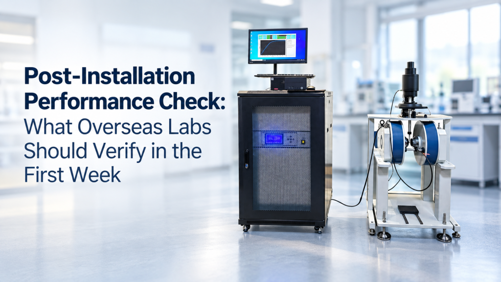
A newly installed scientific instrument can power on successfully and still not be ready for serious research.
This is especially true for exported systems that combine multiple subsystems, such as:
- Electromagnets
- Helmholtz coils
- Hall effect measurement systems
- VSM systems
- MOKE platforms
- Cryogenic sample environments
- Temperature controllers
- Vacuum equipment
- Magnetic-field sensors
- Water chillers
- Automated control software
After international transportation, unpacking, installation, wiring, utility connection, and software setup, the first week should not be treated simply as the beginning of normal measurement.
It should be treated as a post-installation performance check.
The objective is straightforward:
Confirm that the installed system does not merely operate—but performs reproducibly under the customer’s actual laboratory conditions.
This article provides a practical first-week verification framework for overseas laboratories after installing magnetic-field and materials-characterization equipment.
1. Installation Completion Is Not the Same as Performance Verification
A system may successfully:
- Power on
- Communicate with the computer
- Generate magnetic field
- Reach a temperature setpoint
- Display measurement data
and still have unresolved issues.
For example:
- Field polarity may be reversed.
- A Hall probe may be positioned incorrectly.
- Cooling-water flow may be lower than expected.
- A temperature sensor may use the wrong calibration curve.
- A VSM sample may not be centered correctly.
- CSV export may work differently from what the laboratory expected.
- Grounding may introduce additional measurement noise.
- A cryostat may reach low temperature but take much longer than expected.
These problems are much easier to identify during the first week than several months later after they have become mixed into research data.
2. Think of the First Week as Recommissioning After International Transport
Factory testing answers one question:
Did the system perform correctly before shipment?
Post-installation verification answers another:
Does the complete system perform correctly after transportation and installation in the customer’s laboratory?
Between those two points, many things can change:
- Mechanical position
- Cable routing
- Electrical supply
- Cooling conditions
- Sensor position
- Ambient magnetic field
- Vibration
- Computer configuration
- Vacuum integrity
- Sample-holder alignment
The first week should therefore bridge factory acceptance and routine laboratory use.
3. Start with the Final Delivered Configuration
Before testing performance, confirm that everyone is testing the same configuration that was actually ordered.
Compare the installed system against:
- Final quotation
- Purchase order
- Technical specification
- Packing list
- Scope of supply
- Approved configuration drawing
- Deviation list, if applicable
Check:
- Main instrument
- Power supplies
- Sensors
- Sample holders
- Cables
- Chiller
- Cryostat
- Vacuum components
- Computer
- Software
- Optional accessories
Do this before discussing measurement performance.
A missing accessory and a performance failure are different problems.
4. Check Serial Numbers and Major Components
For institutional laboratories, record the installed equipment.
Useful information includes:
- Product model
- Serial number
- Power-supply model
- Sensor serial number
- Controller model
- Computer identification
- Software version
This helps later with:
- Service
- Calibration
- Warranty
- Spare parts
- Technical support
For integrated systems, also record which components belong together.
5. Inspect for Shipping Damage Before Full-Power Operation
International freight can expose equipment to:
- Vibration
- Shock
- Humidity
- Temperature changes
- Repeated handling
Inspect mechanically before applying maximum power.
Look for:
- Loose bolts
- Bent brackets
- Damaged connectors
- Cracked insulation
- Broken optical mounts
- Damaged hoses
- Loose sample stages
- Shifted pole pieces
- Damaged vacuum fittings
Shipping damage is often obvious—but not always.
A system should not be pushed immediately to maximum field simply because there is no visible damage to the shipping crate.
6. Confirm the Laboratory Utilities Against the Site Requirements
Before evaluating performance, verify that the laboratory itself meets the required operating conditions.
Electrical
Confirm:
- Voltage
- Frequency
- Phase
- Current capacity
- Protective earth
- Breaker rating
Cooling
Confirm:
- Chiller operation
- Cooling-water temperature
- Flow
- Hose direction
- No leakage
Environment
Confirm:
- Room temperature
- Humidity
- Ventilation
- Adequate clearance
For high-precision systems, the environment should be considered part of the measurement chain.
ISO/IEC 17025 emphasizes reliable testing and calibration results through competent and consistent laboratory operation; its principles are relevant even for research laboratories that are not seeking formal accreditation because measurement validity depends on controlling the conditions that affect results.
7. Verify Electrical Connections Before Energizing the Magnet
For electromagnets and coil systems, check:
- Coil polarity
- Power cable connections
- Ground connections
- Sensor cables
- Interlock connectors
- Communication cables
For multi-axis Helmholtz coils, confirm:
- X-axis channel
- Y-axis channel
- Z-axis channel
- Positive-field convention
A system can be electrically connected and still have one axis reversed.
That may not become obvious until vector-field experiments begin.
8. First Power-Up Should Be Conservative
Do not make the first commissioning test:
Maximum current → maximum field → one-hour continuous operation.
A better progression is:
Step 1
Power electronics and verify communication.
Step 2
Apply low current.
Step 3
Verify magnetic-field polarity.
Step 4
Increase to moderate field.
Step 5
Monitor cooling and temperature.
Step 6
Proceed toward full operating conditions.
This makes troubleshooting much easier.
9. Verify the Magnetic-Field Direction
For a single-axis magnet, confirm which command produces:
- +B
- −B
For three-axis systems, verify:
- +X
- −X
- +Y
- −Y
- +Z
- −Z
This should match:
- Software convention
- Mechanical labels
- Drawings
- Customer coordinate system
Do not wait until a six-hour automated sequence reveals that one axis was reversed.
10. Compare Field Against Several Current Setpoints
Do not verify magnetic field only at maximum current.
A useful first-week field check includes several points, such as:
- Zero current
- Low field
- Mid-range field
- High field
- Negative field
Compare measured values with:
- Factory test data
- Calibration curve
- Technical specification
Large discrepancies may indicate:
- Different pole gap
- Sensor-position change
- Incorrect current scaling
- Wrong polarity
- Magnet geometry changes
11. Recheck the Electromagnet Pole Gap
For an electromagnet, the field depends strongly on the working gap.
Verify:
- Actual pole gap
- Pole-face parallelism
- Correct pole pieces
- Sample-center location
If factory testing was performed at 20 mm but the installed system is operating at 30 mm, the customer should not expect exactly the same maximum field.
The relevant comparison must use the same geometry.
12. Recheck Helmholtz Coil Geometry
For a Helmholtz or multi-axis coil system, verify:
- Coil spacing
- Coil parallelism
- Common center
- Axis orthogonality
- Structural alignment
If the system was disassembled for shipping, these checks become particularly important.
The coils may still generate field even when their geometry is slightly incorrect.
Field uniformity may be affected before basic operation fails.
13. Confirm the Field Sensor Position
A field measurement is only meaningful if the sensor is measuring the intended location and component.
Verify:
- Probe orientation
- Sensitive axis
- X/Y/Z position
- Height
- Location relative to sample center
For multi-axis probes, verify the coordinate convention.
A sensor moved several millimeters away from the intended center may produce a different result even when the magnet itself is performing correctly.
14. Check Zero-Field Behavior
When magnet current returns to zero, measure the field again.
Possible contributions include:
- Magnet remanence
- Earth’s magnetic field
- Nearby steel
- Other magnetic equipment
This can matter greatly for:
- Low-coercivity materials
- Magnetic sensor calibration
- Helmholtz compensation
- Low-field Hall experiments
- Certain MOKE studies
Do not automatically assume:
0 A = 0 T.
15. Verify Field Uniformity Where It Matters
Not every system requires full field mapping after installation.
But if field uniformity is a critical acceptance parameter, verify it.
Possible locations include:
- Center
- ±X
- ±Y
- ±Z
The test region should match the agreed specification:
- DSV
- Cube
- Plane
- Sample volume
A center-field measurement cannot prove a uniformity specification.
16. Check Cooling Before Long-Duration Magnet Operation
For water-cooled magnets, inspect:
- Inlet
- Outlet
- Flow
- Leakage
- Chiller temperature
Then perform a realistic operating test.
During higher-current operation, monitor:
- Coil temperature
- Cooling-water temperature
- Current stability
- Power-supply status
A cooling system that appears normal at low current may behave differently at maximum thermal load.
17. Run a Stability Test, Not Only a Peak-Performance Test
Maximum performance answers:
Can the system reach the required value?
Stability testing answers:
Can it maintain useful performance over the duration of the experiment?
For an electromagnet, this may mean:
- Set a representative field
- Operate continuously
- Record field over time
For a temperature controller:
- Set a target temperature
- Wait for stabilization
- Monitor drift
For a measurement system:
- Repeat the same measurement several times
This is particularly important when experiments normally last hours rather than minutes.
18. Separate Instrument Stability from Laboratory Stability
If the signal drifts, do not immediately assume the instrument is defective.
Also check:
- Room temperature
- Cooling-water temperature
- AC power
- Nearby magnetic activity
- Grounding
- Vibration
One useful first-week practice is to record environmental conditions alongside instrument data.
That helps distinguish:
equipment drift
from
site-induced drift.
19. Hall Systems Should Begin with a Known Sample
For a Hall effect measurement system, do not begin commissioning with an unknown research sample.
Use a sample whose behavior is already reasonably understood.
Verify:
- Contact configuration
- Sample current
- Magnetic-field polarity
- +B/−B operation
- Voltage measurement
- Resistivity calculation
- Carrier concentration
- Mobility
- Conductivity type
A reference sample isolates system problems from sample problems.
20. Verify +B/−B and +I/−I Sequences
If the Hall system supports automated reversal, explicitly verify that it actually performs the intended sequence.
Check:
- Positive field
- Negative field
- Positive current
- Negative current
- Contact switching
Do not confirm automation simply because the final calculated result appears on the screen.
Understand how the result was produced.
21. Check Raw Hall Data Before Trusting Calculated Results
During the first week, inspect more than the final mobility or carrier-concentration value.
Look at:
- Raw voltages
- Field values
- Current
- Temperature
- Repeated readings
This makes it easier to identify:
- Offset voltage
- Poor contact
- Noise
- Polarity errors
- Incorrect units
Automatic calculation is useful only if the underlying measurement is correct.
22. VSM Systems Should Be Checked with a Stable Reference Sample
For VSM commissioning, use a well-characterized sample if available.
Check:
- Sample centering
- Background
- Loop shape
- Coercivity
- Saturation behavior
- Repeatability
The objective is not necessarily to reproduce an old measurement point by point.
The objective is to confirm that the system produces stable and plausible magnetic data after installation.
23. Verify VSM Sample Centering Separately
A VSM can run an M–H loop even when the sample is not optimally positioned.
Therefore, check centering before judging sensitivity.
Verify:
- Sample height
- Sample-holder position
- Centering procedure
- Repeatability after remounting
If several sample-holder types are included, test the holders that the laboratory expects to use most often.
24. MOKE Systems Need Optical and Magnetic Checks Together
A MOKE system should not be commissioned by testing only the laser or only the magnet.
Verify:
- Laser reaches the sample
- Reflection reaches the detector
- Polarization optics are aligned
- Magnetic field has the correct direction
- Hysteresis loop can be reproduced
For longitudinal MOKE:
- Verify in-plane field geometry.
For polar MOKE:
- Verify out-of-plane field geometry.
Also confirm that pole pieces, cryostat windows, sample holders, or probes do not block the intended optical path.
25. Record a Baseline MOKE Loop
A stable magnetic thin film can provide a useful baseline.
Save:
- Field range
- Sweep rate
- Laser wavelength
- Spot position
- Incidence angle
- Sample orientation
- Resulting loop
This baseline becomes valuable if the optical alignment is disturbed later.
26. Cryogenic Systems Should First Be Tested Without a Valuable Sample
Where practical, perform an initial cryogenic run using:
- Empty sample stage
- Dummy sample
- Non-critical test specimen
Verify:
- Pump-down
- Cooldown
- Base temperature
- Heater function
- Warm-up
- Temperature control
This separates basic system commissioning from research-sample risk.
27. Check Vacuum Performance
Record:
- Starting pressure
- Pump-down behavior
- Base pressure where relevant
- Stability
- Evidence of leakage
For vacuum-integrated cryogenic systems, abnormal pump-down may indicate:
- Loose flange
- Damaged seal
- Contamination
- Incorrect valve position
Finding this in week one is much better than discovering it during a critical experiment.
28. Confirm Temperature Sensor Identity and Calibration
Integrated systems may contain several temperature sensors.
Verify:
- Sensor channel
- Sensor type
- Calibration curve
- Units
- Heater association
A wrong calibration curve can still produce a perfectly plausible-looking temperature display.
Therefore, plausibility is not enough.
Configuration should be checked against the delivered documentation.
29. Test Several Temperature Setpoints
Do not validate temperature control only at room temperature or only at the lowest achievable temperature.
Choose representative points.
For example:
- Near room temperature
- Intermediate temperature
- Low temperature
Check:
- Overshoot
- Settling time
- Stability
- Heater response
This helps reveal control issues that appear only in part of the operating range.
30. Verify Existing Customer Equipment Interfaces
Export projects often reuse equipment already owned by the laboratory.
Examples include:
- Vacuum pumps
- Temperature controllers
- Optical lasers
- Current sources
- Lock-in amplifiers
- LabVIEW systems
During week one, verify these interfaces explicitly.
Do not assume compatibility was proven merely because the connectors physically fit.
Check:
- Mechanical interface
- Electrical signal
- Communication protocol
- Software communication
- Operating sequence
31. Test Every Interface Included in the Purchase Scope
If the supplier promised:
- USB
- RS-232
- RS-485
- Ethernet
- Analog input
- Analog output
test the interfaces that matter to the project.
For example:
- Can the computer connect?
- Can a command be sent?
- Can field be controlled?
- Can data be read?
- Does remote control behave as described?
A connector on the rear panel is not sufficient evidence of usable integration.
32. Verify Data Export Early
This is one of the easiest checks and one of the most frequently postponed.
Export a real dataset.
Check whether it contains:
- Measurement values
- Units
- Field
- Temperature
- Time
- Sample ID
- Relevant metadata
Open it using the software the laboratory actually expects to use:
- Excel
- Origin
- MATLAB
- Python
- LabVIEW
If the data workflow does not work, discovering that in week one gives everyone a chance to resolve it while installation support is still fresh.
33. Save a Copy of the Original Software Configuration
Before users begin changing settings, preserve the original working state.
Back up:
- Software installer
- Drivers
- Calibration files
- Configuration files
- Communication settings
- Automation sequences
- Sample templates
This provides a recovery point.
It is especially useful in university laboratories where many users may later modify software settings.
34. Test Automation with a Short Sequence First
If the system includes automation, do not begin with an overnight sequence.
Start with a short representative workflow.
For example:
- Set field
- Wait
- Measure
- Reverse field
- Measure
- Save data
Then expand to:
- Multiple fields
- Multiple temperatures
- Repeated loops
A five-minute automation test can reveal logic problems before they waste a ten-hour experiment.
35. Test Pause, Stop, and Recovery Functions
Automation is not only about starting a sequence.
Check what happens when the operator:
- Pauses
- Stops
- Aborts
- Restarts
Also understand:
- Are completed data preserved?
- Does the magnet return to zero?
- Does temperature remain controlled?
- Does software recover communication?
These behaviors are worth learning before an emergency occurs.
36. Verify Safety Interlocks
Depending on the system, check the relevant interlocks according to the manufacturer’s instructions.
Examples include:
- Cooling-flow protection
- Overtemperature
- Overcurrent
- Emergency stop
- Vacuum protection
- Door/enclosure protection
The purpose is not to intentionally create unsafe conditions.
Use the documented verification procedure.
A connected interlock cable does not prove the protective function operates correctly.
37. Confirm Alarm Messages and Operator Response
Users should understand basic alarms such as:
- Overtemperature
- Insufficient cooling
- Communication failure
- Vacuum alarm
- Sensor error
Training should include:
What does the message mean?
and:
What should the operator do next?
This reduces unnecessary support requests and prevents users from repeatedly resetting a real hardware protection condition.
38. Training Should Include Routine Operation, Not Only a Demonstration
A supplier can operate the system while the customer watches.
That is not the same as training.
By the end of the first week, at least one local user should ideally be able to perform a complete routine workflow.
For example:
- Power on
- Mount sample
- Configure experiment
- Run measurement
- Export data
- Return system to safe state
- Shut down correctly
The best test of training is simple:
Can the customer’s operator perform the workflow without the trainer taking over?
39. Have the User Repeat the Procedure Independently
A useful training approach is:
First Run
Supplier demonstrates.
Second Run
Customer performs with guidance.
Third Run
Customer performs independently.
This reveals practical questions that do not appear during a passive presentation.
Examples:
- Which button starts the sweep?
- When should the chiller be started?
- Where is the raw file stored?
- How is the sample centered?
- Which axis is positive?
These are exactly the questions that need answers before the supplier’s installation support ends.
40. Confirm Routine Shutdown
Shutdown procedures matter too.
Check the correct order for:
- Returning magnetic field to zero
- Reducing current
- Stopping temperature programs
- Warming cryogenic systems
- Venting where appropriate
- Turning off cooling
- Closing software
Manufacturer-specific instructions should take priority.
Improper shutdown may create problems that do not appear until the next startup.
41. Do Not Make Unnecessary Configuration Changes During Week One
New users often want to optimize everything immediately.
Avoid changing too many variables at once.
For the first week, keep:
- Known software version
- Factory configuration
- Standard sample holder
- Standard measurement sequence
until baseline operation is established.
Otherwise, if something stops working, nobody knows whether the cause was:
- Installation
- Hardware
- Software
- User modification
Establish a stable baseline first.
42. Keep a First-Week Issue Log
Create a simple record.
For each issue, note:
- Date
- Symptom
- Operating condition
- Screenshot/photo
- Reproduction steps
- Resolution
Classify issues if useful:
Installation
Cable, mechanical, utility.
Training
User procedure unclear.
Software
Configuration, driver, export.
Performance
Field, temperature, noise.
Documentation
Manual or instruction missing.
This makes remote support much more efficient.
43. Separate Questions from Defects
During commissioning, users will discover both.
Example:
Question:
“How do I change the M–H sweep rate?”
That is training.
Defect:
“Commanded 1 T, but measured field cannot exceed 0.6 T at the agreed gap.”
That is a performance issue.
Keeping the distinction clear helps supplier and customer resolve issues faster.
44. Record Baseline Performance Before Routine Research Begins
At the end of the first week, save a baseline package.
It might include:
Magnet System
- Field-current points
- Zero-field reading
- Stability test
Hall System
- Reference sample dataset
VSM
- Reference hysteresis loop
MOKE
- Standard loop / optical configuration
Cryogenic System
- Pump-down
- Cooldown
- Base temperature
- Stability
This becomes the laboratory’s local reference.
Months later, if performance appears different, there is something concrete to compare against.
45. Baseline Data Are More Useful Than Memory
Statements such as:
“I think it used to be quieter.”
or:
“I remember the system cooling faster.”
are difficult to troubleshoot.
Measured baseline data allow comparisons such as:
- Field drift increased from X to Y
- Cooldown time increased by Z%
- VSM noise increased
- Hall reference sample changed
- Vacuum pump-down slowed
Good post-installation records convert subjective concerns into engineering questions.
46. Traceability Matters When Measurement Results Matter
For laboratories performing quantitative measurement, calibration and reference documentation should be reviewed during commissioning.
NIST emphasizes that metrological traceability applies to measurement results through a documented chain to recognized references and appropriate consideration of measurement uncertainty; simply possessing a calibration certificate does not automatically establish the validity of every subsequent measurement made under different conditions.
The practical implication after installation is:
- Verify the correct sensor is installed.
- Verify calibration information matches that sensor.
- Verify the sensor is used correctly.
- Verify the system configuration matches the intended measurement.
Calibration documentation and correct installation must work together.
47. ISO/IEC 17025 Provides a Useful Quality Principle
ISO/IEC 17025 is formally aimed at testing and calibration laboratories and is not a mandatory operating standard for every university research laboratory.
However, its central principle is useful here:
Reliable results require competent operation and controlled processes, not merely ownership of sophisticated equipment.
ISO states that ISO/IEC 17025 helps laboratories demonstrate competence and generate valid results and is relevant not only to calibration organizations but also to universities and research centres.
A first-week post-installation check follows the same practical logic:
verify the system, the operating conditions, and the measurement workflow before treating the results as routine data.
48. What Should Be Verified by Day 1?
A practical first-week schedule can begin with basic installation.
Day 1 — Installation and Safety
Confirm:
- Delivered components
- Mechanical installation
- Electrical supply
- Grounding
- Cooling
- Basic communication
- Interlocks
- Low-power operation
Do not focus yet on advanced experiments.
The objective is a safe and stable installed system.
49. What Should Be Verified by Days 2–3?
Once basic operation is established:
Days 2–3 — Core Performance
Check:
- Maximum practical field
- Positive/negative field
- Field-current relationship
- Temperature control
- Vacuum
- Sensor response
- Sample centering
- Reference measurements
Now compare results with factory or agreed technical data.
50. What Should Be Verified by Days 3–5?
Next move into normal workflow.
Days 3–5 — Interfaces and Software
Verify:
- Automation
- Data export
- External interfaces
- Sample-holder changes
- Routine measurement procedures
- Error handling
This is where hidden usability problems often appear.
51. What Should Be Verified by the End of Week One?
Days 5–7 — Stability and User Handover
Complete:
- Longer-duration operation
- Repeatability tests
- Reference-sample comparison
- Independent customer operation
- Issue log review
- Documentation check
- Baseline data archive
By the end of the week, the laboratory should know not only that the system operates but what “normal” performance looks like.
52. A Practical First-Week Post-Installation Checklist
Delivery and Configuration
- Correct system received
- Major serial numbers recorded
- Accessories confirmed
- Options confirmed
Mechanical
- Shipping damage checked
- Magnet alignment checked
- Pole gap confirmed
- Coil geometry confirmed
- Sample stage checked
Electrical
- Voltage / frequency / phase verified
- Grounding confirmed
- Coil polarity verified
- Communications working
Cooling
- Chiller functioning
- Flow confirmed
- No leaks
- Continuous operation tested
Magnetic Performance
- +B verified
- −B verified
- Zero-field condition checked
- Multiple field points checked
- Uniformity checked where required
Measurement
- Reference sample tested
- Repeatability checked
- Noise/background reviewed
Cryogenic / Vacuum
- Pump-down tested
- Base temperature checked
- Temperature stability checked
- Sensor configuration confirmed
Software
- Data acquisition verified
- Export tested
- Automation tested
- Configuration backed up
Interfaces
- Existing customer equipment connected
- Communication verified
- Relevant I/O functions tested
Safety
- Interlocks verified
- Alarm behavior understood
- Shutdown procedure confirmed
Training
- Customer runs system independently
- Routine workflow confirmed
- Basic troubleshooting understood
Records
- Baseline data saved
- Issue log completed
- Final configuration documented
That is a much stronger installation result than simply recording:
“System powered on successfully.”
53. How Cryomagtech Approaches Post-Installation Verification
Cryomagtech systems can involve combinations of:
- Electromagnets
- Helmholtz coils
- Bipolar power supplies
- Hall measurement systems
- VSM platforms
- MOKE systems
- Cryogenic environments
- Temperature control
- Vacuum equipment
- Magnetic-field measurement
For exported system projects, the useful handover point is not simply when the equipment arrives.
It is when the customer can verify the essential functions, reproduce a representative measurement, export usable data, and operate the system independently.
👉 Product link placeholder: Cryomagtech Magnet & Field Systems – Electromagnets and Helmholtz Coils
For integrated measurement platforms:
👉 Product link placeholder: Cryomagtech Hall, VSM, MOKE & Cryogenic Measurement Systems
For customized installations, maintaining factory baseline data, installation records, and first-week verification results can make future troubleshooting and system relocation significantly easier.
54. Key Takeaways
The first week after installation is one of the most important periods in the life of an exported research system.
A good post-installation performance check should verify:
- Delivered configuration
- Mechanical installation
- Electrical power
- Grounding
- Cooling
- Magnetic-field direction
- Field performance
- Sensor position
- Temperature
- Vacuum
- Reference measurement
- Stability
- Software
- Data export
- External interfaces
- Safety interlocks
- Operator training
The goal is not to retest every factory specification unnecessarily.
It is to establish confidence that:
the delivered equipment + the new laboratory + the installed configuration + the local operator
work together as one measurement system.
A successful installation means the equipment turns on.
A successful handover means the laboratory can trust the system, reproduce a measurement, understand its normal operating behavior, and continue working without depending on guesswork.
For overseas scientific equipment projects, that second standard is the one that matters.
References
1. ISO/IEC 17025 — General Requirements for the Competence of Testing and Calibration Laboratories
ISO/IEC 17025 provides an internationally recognized framework for competent and consistent laboratory operation and reliable testing and calibration results. ISO notes that the standard is relevant to testing and calibration organizations as well as universities and research centres. The underlying principles are useful when establishing post-installation verification and baseline measurement procedures.
Check source:
https://www.iso.org/ISO-IEC-17025-testing-and-calibration-laboratories.html
2. NIST — Policy on Metrological Traceability
NIST explains that measurement traceability depends on a documented chain connecting measurement results to recognized references and appropriate measurement uncertainty, reinforcing why calibration documentation, sensor identity, installation conditions, and actual measurement procedures must be considered together.
Check source:
https://www.nist.gov/calibrations/traceability