
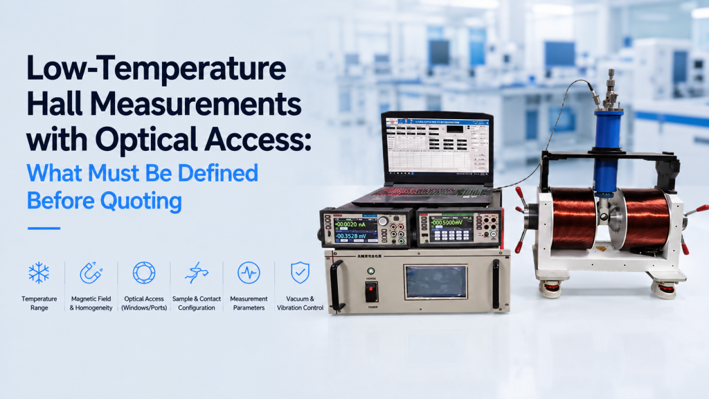
Low-temperature Hall measurements with optical access combine several experimental requirements that are relatively straightforward when considered separately—but strongly coupled when integrated into one system.
A typical request may sound simple:
“We need Hall measurements at low temperature with a magnetic field and optical illumination.”
For an engineering quotation, that is not enough.
The required temperature range, magnetic field, sample geometry, wavelength, beam direction, optical spot size, vacuum environment, electrical contacts, and measurement sequence can all change the system architecture.
This article explains the key parameters that should be defined before requesting a quotation for a cryogenic Hall measurement system with optical access.
1. Why Optical-Access Hall Measurements Need More Definition
A conventional Hall measurement system already combines:
- Sample current
- Hall voltage measurement
- Magnetic field
- Sample geometry
- Electrical contacts
- Temperature control
- Data acquisition
Adding low temperature introduces:
- Cryostat geometry
- Vacuum requirements
- Thermal anchoring
- Temperature sensors
- Electrical feedthroughs
- Cooling method
Adding optical access introduces another layer:
- Optical windows
- Wavelength range
- Beam diameter
- Beam direction
- Optical alignment
- Window transmission
- Illumination-induced heating
The result is not simply a Hall system with a window added to it.
The electrical, thermal, magnetic, mechanical, and optical designs must work together.
2. Define the Sample Before Defining the Instrument
Sample Dimensions
Start with the physical sample:
- Length and width
- Thickness
- Substrate dimensions
- Maximum sample size
- Whether multiple sample sizes must be supported
A 5 × 5 mm thin film and a 20 × 20 mm wafer piece may require very different holders, wiring arrangements, and optical apertures.
Hall Geometry
The measurement geometry must also be identified.
Common options include:
- Van der Pauw
- Hall bar
- Rectangular four-terminal sample
- Custom multi-terminal device
For Van der Pauw measurements, contact dimensions and placement matter. NIST notes that Hall measurements can be strongly affected by sample geometry, contact placement, and offset voltages. Hall signals themselves can also be very small, sometimes on the microvolt scale.
This means the quotation should not assume that every sample can use the same standard holder.
Electrical Contact Requirements
Define:
- Number of electrical contacts
- Contact positions
- Expected sample resistance
- Maximum excitation current
- Connector type
- Whether removable probes or wire bonding will be used
If the sample is extremely high resistance or produces a very small Hall voltage, low-noise electrical design becomes much more important.
3. Define the Real Temperature Range
“Low temperature” is not a specification.
It could mean:
- Approximately 80 K using liquid nitrogen
- 10–300 K
- 4–300 K using a cryocooler
- Below 4 K
- Low temperature plus controlled heating above room temperature
These are fundamentally different systems.
Minimum Temperature
The required base temperature determines much of the cryogenic architecture.
For example:
- LN₂ systems are relatively simple for measurements around 77–80 K and above.
- Closed-cycle cryostats may be appropriate when temperatures near 4 K are required.
- Sub-4 K operation usually requires a significantly more specialized cryogenic platform.
Maximum Temperature
Do not define only the lowest temperature.
Researchers should also specify whether measurements are required:
- Only below room temperature
- From cryogenic temperature to 300 K
- Above 300 K
- During both cooling and heating
A system designed for 80–300 K operation should not automatically be assumed to support 400 K or 500 K.
4. Define the Magnetic Field Requirements
The next major question is the magnetic field.
Maximum Field
Specify the actual required field range, for example:
- ±0.5 T
- ±1 T
- ±2 T
- Higher-field superconducting magnet operation
The maximum field directly affects magnet selection, pole geometry, cooling requirements, power supply, and optical access.
Field Direction
For many conventional Hall measurements, the magnetic field is applied perpendicular to the sample plane.
NIST describes Hall measurements using a magnetic field applied along the sample’s z-axis and shows the importance of measurements under both positive and negative magnetic field directions.
But optical experiments introduce another important question:
What is the relationship between the magnetic field, sample surface, and optical beam?
Possible configurations include:
- Light perpendicular to sample, parallel to magnetic field
- Light perpendicular to sample, magnetic field in-plane
- Light incident at an angle
- Transmission geometry
- Reflection geometry
This should be defined before mechanical design begins.
Field Reversal
A quotation should also clarify whether the experiment requires:
- +B only
- +B and −B
- Automatic bipolar field sweeping
- Manual magnet reversal
- Field cycling at multiple temperatures
Field reversal is particularly important in Hall measurements because comparing positive and negative magnetic-field data helps suppress offset contributions caused by imperfect contact symmetry and sample geometry.
5. Optical Access Is More Than a Window
One of the most common incomplete RFQs is:
“We need optical access.”
That statement leaves most of the engineering work undefined.
Wavelength Range
The optical wavelength must be specified.
Examples include:
- 365 nm UV
- 405 nm
- 532 nm
- 633 nm
- 808 nm
- 1064 nm
- Broadband visible illumination
- UV–Vis–NIR range
Window materials have different transmission ranges.
The correct optical window cannot be selected until the wavelength is known.
Beam Diameter and Spot Size
Specify both:
- Beam diameter entering the cryostat
- Required spot size on the sample
These are not necessarily the same.
The system may need enough clear aperture for the incoming beam while still focusing the light onto a much smaller region of the sample.
Optical Power
Optical power matters because illumination can affect both the electrical state and temperature of the sample.
Define:
- Optical power at the source
- Expected power reaching the sample
- Whether power must be variable
- Continuous-wave or pulsed illumination
For highly temperature-sensitive measurements, even modest illumination can introduce local heating.
6. Decide Between Reflection and Transmission Geometry
This decision can significantly change cryostat and sample-holder design.
Reflection Geometry
In reflection mode, light enters the cryostat, reaches the sample, and the reflected beam returns toward the same side.
This may require:
- One primary optical access direction
- Sufficient space for incident and reflected beams
- Angular optical access if normal incidence is not used
Transmission Geometry
Transmission experiments require the light to pass through:
- External vacuum window
- Cryogenic radiation shields
- Sample holder
- Sample or substrate
- Opposite-side optical aperture
The mechanical design therefore becomes more restrictive.
A sample holder optimized only for electrical Hall measurements may physically block the optical beam.
This is why transmission requirements should be disclosed before quotation—not after the cryostat has already been designed.
7. Illumination Conditions Are Part of the Measurement
For photo-Hall and optoelectronic characterization, illumination is not simply an accessory.
It changes the material being measured.
The Nature paper Carrier-resolved photo-Hall effect demonstrates how combining Hall measurements with controlled optical excitation can provide information about photogenerated charge carriers beyond conventional dark Hall characterization.
Another practical consequence follows:
“Optical access” should not be treated as a binary specification.
The experiment should define whether measurements will be performed under:
- Dark conditions
- Constant illumination
- Multiple optical power levels
- Multiple wavelengths
- Light ON/OFF cycles
- Simultaneous field and optical sweeps
For photo-sensitive semiconductors, perovskites, quantum materials, and optoelectronic devices, these conditions can be part of the experimental variable itself.
8. Temperature Measurement Under Illumination Needs Attention
Cryogenic temperature control becomes more complicated when light reaches the sample.
The cryostat may report a stable temperature while the illuminated area of the sample is slightly warmer.
Several parameters therefore matter:
- Temperature sensor position
- Distance between sensor and sample
- Thermal contact between sample and holder
- Optical power
- Sample absorption
- Substrate thermal conductivity
- Stabilization time after changing illumination
For high-precision temperature-dependent transport measurements, simply stating “temperature stability ±X K” does not completely describe the temperature of the illuminated sample.
The thermal design must consider where the heat is generated and where the temperature is actually measured.
9. Define the Vacuum or Sample Environment
Optical-access cryogenic Hall measurements may operate under:
- High vacuum
- Low vacuum
- Exchange gas
- Controlled atmosphere
- Flow cryostat conditions
The required environment affects:
- Window design
- Feedthrough selection
- Sample exchange procedure
- Pumping system
- Cryostat structure
- Thermal performance
The RFQ should therefore specify whether the laboratory already has:
- Vacuum pump
- Turbo pump
- Vacuum gauge
- Gas handling equipment
- Temperature controller
If existing equipment will be reused, model numbers and interfaces should ideally be provided.
10. Electrical and Optical Synchronization Should Be Defined
A basic system may simply illuminate the sample continuously while Hall data are collected.
More advanced experiments may require synchronization between:
- Magnetic field
- Sample current
- Temperature
- Optical illumination
- Wavelength
- Optical power
- Hall voltage acquisition
For example, a measurement sequence might be:
- Stabilize temperature
- Measure dark Hall signal
- Turn illumination ON
- Wait for stabilization
- Sweep magnetic field from −B to +B
- Record Hall voltage
- Change optical power
- Repeat
- Change temperature
- Repeat
If this level of automation is required, it should be identified before quotation because software and control architecture become part of the system scope.
11. What Should Be Defined Before Requesting a Quotation?
A useful RFQ for a low-temperature Hall system with optical access should ideally provide the following information.
Sample
- Material type
- Sample dimensions
- Thickness
- Hall bar or Van der Pauw geometry
- Number of contacts
- Expected resistance range
Temperature
- Minimum temperature
- Maximum temperature
- Required stability
- Cooling method preference, if any
Magnetic Field
- Maximum positive and negative field
- Required field direction
- Sweep requirements
- Required field uniformity
Optical Requirements
- Wavelength or wavelength range
- Optical power
- Beam diameter
- Required spot size
- Reflection or transmission geometry
- Beam direction relative to magnetic field
- Continuous or pulsed illumination
Environment
- Vacuum requirement
- Existing vacuum equipment
- Existing temperature controller
- Space or installation constraints
Measurement
- Required Hall parameters
- Dark/light comparison
- Automated field sweeps
- Temperature sweeps
- Optical power sweeps
- Data export requirements
Providing these parameters early usually saves much more time than repeatedly modifying the system after engineering has started.
12. How Cryomagtech Approaches Integrated Hall + Cryogenic + Optical Systems
Cryomagtech can evaluate Hall measurement systems that combine:
- Hall effect measurement
- Electromagnet systems
- Bipolar magnetic-field control
- Low-temperature sample environments
- Cryogenic temperature control
- Optical access
- Custom sample holders
- Electrical feedthroughs
- Data acquisition and system integration
The objective is not simply to combine several instruments.
The important part is making sure the sample, magnetic field, optical beam, cryogenic environment, and electrical measurement geometry remain compatible with one another.
👉 Product link placeholder: Cryomagtech Hall Effect Measurement Systems / Cryogenic Hall Systems
For customized systems, providing the sample geometry, temperature range, magnetic field, and optical requirements at the RFQ stage usually allows a much more realistic technical proposal and quotation.
13. Key Takeaways
Low-temperature Hall measurements with optical access require more definition than a conventional Hall system.
Before requesting a quotation, determine:
- Sample geometry and electrical contacts
- Minimum and maximum temperature
- Magnetic field strength and direction
- +B/−B reversal requirements
- Optical wavelength
- Beam and spot size
- Reflection or transmission geometry
- Optical power
- Vacuum environment
- Measurement and synchronization sequence
The most expensive problems usually occur when one subsystem is specified without considering the others.
A cryostat may reach the correct temperature.
A magnet may reach the correct field.
An optical window may transmit the correct wavelength.
But unless all three are designed around the same sample geometry and measurement sequence, the complete experiment may still not work as intended.
References
1. NIST – Resistivity and Hall Measurements
Hall measurement procedures, Van der Pauw geometry, magnetic-field reversal, sample geometry, and common measurement errors.
NIST – Resistivity and Hall Measurements
2. Nature – Carrier-resolved photo-Hall effect
O. Gunawan et al., Nature 575, 151–155 (2019). Demonstrates Hall characterization under controlled optical excitation for resolving photogenerated carrier properties.
Nature – Carrier-resolved photo-Hall effect