
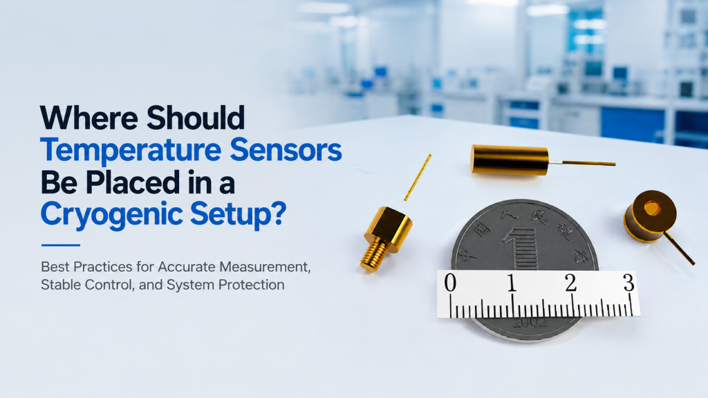
A cryogenic temperature controller shows:
4.20 K
So what is actually at 4.20 K?
Is it:
- The cryocooler cold head?
- The copper sample stage?
- The temperature sensor itself?
- The sample mounted on the stage?
- The cryostat shield?
- The probe touching the sample?
These temperatures may be close.
But they are not automatically the same.
This is one of the most underestimated problems in low-temperature experiments:
A temperature sensor measures the temperature of the sensor—not automatically the temperature of the sample you care about.
NIST’s cryogenic measurement guidance states this point very clearly. A thermometer measures its own temperature, and differences between thermometer and sample can arise from lead-wire heat conduction, sensor self-heating, and imperfect thermal contact. NIST therefore emphasizes good thermal contact and proper thermal anchoring of the sensor leads.
Lake Shore’s current cryogenic sensor installation checklist gives similarly practical guidance: place the sensor close to the location whose temperature matters, keep it appropriately separated from heaters, thermally anchor wires at temperature stages, and control optical/radiative and wiring-related heat loads.
This means cryogenic temperature sensor placement is not a small installation detail.
It can determine whether:
- The displayed temperature represents the sample
- PID control is stable
- Temperature sweeps are trustworthy
- Thermal gradients are detected
- Magnet experiments report the correct temperature
- Two laboratories can reproduce the same measurement
For buyers selecting cryogenic thermometers, temperature controllers, monitors, and integrated low-temperature systems, the most useful question is therefore not:
“How many temperature sensors does the system have?”
It is:
“What temperature does each sensor actually represent, and why is it mounted there?”
1. The First Rule: A Sensor Measures Its Own Temperature
This principle sounds obvious.
In practice, it changes how a cryogenic system should be designed.
Imagine:
Sample stage sensor = 10.00 K
The sample could actually be:
- 9.8 K
- 10.0 K
- 10.5 K
- 12 K
depending on:
- Thermal contact
- Sample mounting
- Wiring
- Radiation
- Probe heat load
- Measurement current
- Heater position
NIST explicitly notes that thermometer uncertainty applies to the thermometer itself, not automatically to the sample whose temperature is being inferred.
That is the starting point for every cryogenic sensor-placement decision.
2. “Cryostat Temperature” Is Too Vague
A buyer may say:
“The cryostat is at 20 K.”
But a cryostat can contain many temperatures simultaneously:
- First-stage cold head: 45 K
- Radiation shield: 55 K
- Second-stage cold head: 8 K
- Sample platform: 10 K
- Sample: 11 K
- Probe arm: 25 K
All of these can be correct.
Cryogenic systems naturally contain thermal gradients.
A temperature value therefore needs a location.
Better Reporting
Instead of:
Temperature = 10 K
write:
Sample-stage temperature = 10 K
or:
Control sensor located beneath the sample stage = 10 K
That is much more scientifically meaningful.
3. Start by Defining the Temperature of Interest
Before deciding where to install a sensor, ask:
What temperature do we actually need to know?
Possible answers include:
- Cold-head temperature
- Sample-stage temperature
- Actual sample temperature
- Radiation-shield temperature
- Magnet temperature
- Heater-block temperature
- Probe temperature
- Gas temperature
These are different measurement objectives.
The sensor should be positioned to represent the temperature relevant to the experiment.
4. The Best Sensor Location Is Usually Close to the Temperature of Interest
Lake Shore’s installation checklist explicitly recommends sensor placement close to the location whose temperature is of interest.
That seems straightforward.
But “close” means:
thermally close
not merely:
geometrically close.
A sensor 3 mm away across a poor thermal interface may represent the sample worse than a sensor 20 mm away mounted on a highly conductive copper block.
The thermal path matters more than ruler distance alone.
5. Thermal Contact Is What Makes the Reading Meaningful
Suppose a temperature sensor is placed on a copper sample platform.
If the interface between them contains:
- Air gap
- Loose contact
- Poor adhesive
- Oxide layer
- Surface contamination
the sensor may not track the stage accurately.
NIST notes that thermal grease or suitable mounting methods can improve thermal contact between thermometer packages and the surface being measured.
Lake Shore’s installation guidance likewise emphasizes:
- Surface preparation
- Thermal interface material
- Mechanical securing method
- Sensor-package-specific mounting
as part of correct sensor installation.
Sensor selection and sensor mounting therefore cannot be separated completely.
6. A Perfect Calibration Cannot Fix Bad Thermal Contact
Suppose you purchase a highly accurate calibrated cryogenic thermometer.
Calibration uncertainty:
±5 mK
Excellent.
But poor mounting creates a:
300 mK
temperature difference between the sensor and the sample.
The measurement is not accurate to ±5 mK at the sample.
The sensor may accurately report:
the wrong thermal location.
Important Principle
Calibration accuracy ≠ sample-temperature accuracy.
The complete error chain can include:
- Calibration uncertainty
- Instrument measurement uncertainty
- Self-heating
- Magnetic-field error
- Thermal-gradient error
- Mounting error
- Lead-wire heat leak
For real experiments, thermal placement can dominate the error budget.
7. Do Not Put the Control Sensor Directly on the Heater Without Thinking
A common control arrangement contains:
- Heater
- Control sensor
- Sample
If the sensor sits very close to the heater but the sample is thermally farther away, the controller may see:
20.00 K
while the sample is still:
17 K
during warm-up.
The controller believes the target has been reached.
The sample has not.
Lake Shore’s sensor installation checklist explicitly advises considering separation from heaters as part of placement.
The goal is to measure the controlled thermal mass, not merely the heater’s local hot spot.
8. But the Control Sensor Cannot Be Too Far From the Heater Either
The opposite extreme creates another problem.
Suppose:
- Heater is at one end of a long cold finger.
- Control sensor is at the other end.
- Thermal conductance between them is weak.
The controller increases heater power.
The distant sensor responds slowly.
The PID loop continues adding heat.
Eventually the delayed heat reaches the sensor.
Temperature overshoots.
Possible result:
- Oscillation
- Long settling time
- Poor ramp control
So control-sensor placement is a compromise between:
representing the target temperature
and:
responding fast enough to the heater.
9. Control Sensor and Sample Sensor Do Not Have to Be the Same Sensor
This is one of the most useful cryogenic design concepts.
A system may use:
Control Sensor
Used by PID to regulate heater power.
Sample Sensor
Used to report the temperature most relevant to the experiment.
They may be installed at different locations.
For example:
Control sensor: embedded in copper sample stage near heater.
Sample sensor: mounted close to the actual specimen.
This architecture can provide both:
- Stable control
- Better knowledge of actual sample temperature
10. Why One Sensor May Not Be Enough
Suppose one sensor is installed under the sample stage.
You know:
stage temperature
But you do not know whether:
sample temperature = stage temperature.
A second sensor can reveal:
- Sample-to-stage gradient
- Thermalization delay
- Effect of probe contact
- Heating from measurement current
This is particularly useful when:
- Temperature accuracy matters strongly
- Samples dissipate power
- Probe arms bring heat
- Magnetic-field sweeps generate heat
A second sensor is not automatically required.
But it can answer a different thermal question.
11. Think in Terms of “Control,” “Monitor,” and “Diagnostic” Sensors
A useful sensor architecture separates three functions.
Control Sensor
Feeds the PID loop.
Monitoring Sensor
Measures an important independent thermal point.
Diagnostic Sensor
Helps understand system behavior.
For example:
| Sensor | Location | Purpose |
|---|---|---|
| T1 | Sample stage | PID control |
| T2 | Sample | Actual experiment temperature |
| T3 | Cold head | Cooling-system health |
| T4 | Radiation shield | Thermal diagnostics |
This immediately explains why a cryogenic monitor may still be useful even when a temperature controller already exists.
12. The Cold-Head Sensor Does Not Automatically Represent the Sample
This mistake is common in closed-cycle systems.
Suppose:
Second-stage cold head = 4.2 K
The sample may be:
6.5 K
because between them are:
- Copper braids
- Mechanical joints
- Sample stage
- Wiring
- Radiation
- Probe load
The temperature difference follows the thermal resistance and heat flow through the system.
Therefore:
cold-head temperature
is valuable for monitoring refrigerator performance.
It is not always the right variable for reporting experimental sample temperature.
13. A Sample-Stage Sensor Is Usually More Relevant Than a Cold-Head Sensor
For many materials experiments, the sample sits on a thermally controlled stage.
A sensor mounted directly on that stage generally provides more relevant information than a sensor inside the cryocooler.
This is particularly true when the stage includes its own:
- Heater
- Copper block
- Sample holder
The stage becomes the controlled thermal node.
14. But the Sample Itself Can Still Differ From the Stage
Lake Shore has demonstrated this experimentally in cryogenic probe stations.
In one test, the temperature measured directly on a device differed significantly from the temperature reported by the sample-stage sensor depending on how probe arms were thermally anchored. In its worst tested configuration, the stage was around 6.46 K while the device temperature rose above 41 K because unanchored probes and radiation introduced substantial heat.
That is an extreme example.
But it demonstrates the core principle:
Stage temperature does not automatically equal device temperature.
15. Probe Arms Can Be Major Thermal Paths
Cryogenic electrical probing creates a difficult requirement.
The probe must physically connect:
room-temperature mechanics
to:
cryogenic sample.
That creates a conductive heat path.
Without proper thermal anchoring, the probe can deliver heat directly to the sample.
Lake Shore’s probe-station measurements demonstrate that probe thermal anchoring can strongly influence actual device temperature.
If the experiment uses:
- Probe arms
- RF probes
- Optical fibers
- Mechanical shafts
their thermal influence should be considered when deciding where temperature sensors belong.
16. Sensor Wires Are Also Heat Pipes
A temperature sensor is connected to room-temperature electronics through wires.
Those wires can conduct heat from:
300 K
toward:
4 K
or lower.
NIST specifically warns that electrical leads can create heat leaks that cause the thermometer itself to become warmer than the sample unless the wires are properly thermally anchored.
This means sensor installation has two thermal problems:
- Mount the sensor correctly.
- Mount the sensor wires correctly.
Ignoring the second can compromise the first.
17. Thermal Anchoring the Sensor Leads Is Essential
A typical cryogenic system may contain stages at:
- 300 K
- 50 K
- 4 K
Instead of running sensor wires directly from room temperature to the sensor, the leads can be thermally anchored at intermediate stages.
Lake Shore recommends thermally anchoring sensor wires at multiple temperatures to prevent excessive heat conduction through the leads to the sensing element.
Conceptually:
300 K → anchor at 50 K → anchor at 4 K → sensor
This intercepts heat before it reaches the measurement location.
18. Lead Anchoring Is Especially Important for the Lowest-Temperature Sensors
At:
300 K
a few milliwatts may be irrelevant.
At:
4 K
the same heat leak may matter substantially.
At:
100 mK
it can be catastrophic.
Therefore the importance of:
- Wire material
- Wire gauge
- Thermal anchoring
- Excitation power
increases dramatically as the target temperature falls.
NIST’s cryogenic measurement review treats thermal anchoring of thermometers and leads as a core part of low-temperature measurement practice.
19. Thin, Low-Thermal-Conductivity Wires Reduce Heat Leak
Sensor wiring often uses materials selected to reduce thermal conduction, such as:
- Phosphor bronze
- Manganin
- Other appropriate cryogenic alloys
rather than simply using thick copper wires from room temperature to the cold stage.
But lower electrical conductivity can affect:
- Resistance
- Measurement method
This is why four-wire resistance measurement can be valuable for RTD-type sensors.
Sensor wiring is therefore an electrical and thermal design simultaneously.
20. Four-Wire Measurement Helps Separate Lead Resistance From Sensor Resistance
For resistance thermometers, a four-wire arrangement can reduce errors associated with lead resistance.
Lake Shore strongly recommends four-lead wiring for RTD-type temperature probes in appropriate configurations.
But remember:
Four-wire measurement helps solve:
electrical lead-resistance error.
It does not automatically solve:
thermal conduction through those same leads.
Electrical compensation and thermal anchoring address different problems.
21. The Sensor Should Be Thermally Anchored Independently From Its Leads
NIST makes an important distinction:
The electrical leads themselves should be thermally anchored independently of the thermometer so that heat conducted through the wires does not significantly disturb sensor temperature.
This is a subtle but valuable installation principle.
The sensor mount should establish:
sensor ↔ sample/stage thermal contact
while the wiring architecture minimizes unwanted:
room temperature → sensor heat flow.
22. Do Not Let the Sensor “See” a Warm Surface If Radiation Matters
Inside a vacuum cryostat, conduction through gas becomes very small.
Radiative heat transfer can then become more important.
Lake Shore’s installation checklist advises that the sensor should not have direct view of surfaces at substantially different temperatures and suggests the use of:
- Baffles
- Reflective shielding
- Superinsulation
where appropriate.
A sensor directly exposed to a 300 K window may read differently from a well-shielded sensor on the same nominal cold stage.
23. Vacuum Does Not Mean “No Heat Transfer”
In high vacuum, you reduce gas conduction.
You do not eliminate:
- Solid conduction
- Wiring conduction
- Radiation
- Sample self-heating
Therefore a sensor can still be warmer than the mechanical surface to which it is attached if the thermal paths are not controlled properly.
This is why cryogenic thermometry requires thermal design rather than simply putting a sensor “inside the vacuum.”
24. Sensor Self-Heating Can Create Its Own Temperature Error
Resistance sensors must be electrically excited to measure them.
That excitation dissipates:
P = I²R
inside the thermometer.
NIST notes that thermometer excitation can cause self-heating and increase the thermometer temperature above its surroundings.
At very low temperatures, tiny powers can matter.
Therefore:
- Sensor excitation
- Thermal mounting
- Sensor location
all interact.
25. A Sensor With Poor Thermal Contact Is More Vulnerable to Self-Heating
Suppose two identical sensors dissipate the same measurement power.
Sensor A
Strong thermal connection to copper block.
Sensor B
Poor thermal connection.
Sensor B will generally experience a larger temperature rise from the same self-heating because it cannot remove the generated heat as effectively.
This is another reason calibration data cannot compensate for poor mounting.
26. Control Sensors Should Not Necessarily Be the Most Accurate Sensors
This may sound surprising.
For PID control, important qualities include:
- Sensitivity
- Repeatability
- Response time
- Appropriate thermal coupling
- Suitable temperature range
For final scientific temperature reporting, absolute accuracy may carry more weight.
One system could therefore use:
Sensor A for fast, stable control
and:
Sensor B for high-accuracy sample monitoring.
The optimal choice depends on experiment design.
27. Sensor Response Time Matters During Temperature Sweeps
Suppose the stage ramps:
5 K/min
but the sensor responds slowly because:
- Massive package
- Poor mounting
- Weak thermal contact
The displayed temperature may lag the actual thermal node.
NIST discusses thermal response time as an important dynamic property of cryogenic thermometers and notes that sufficient time must be allowed for equilibrium after thermal changes.
Fast ramps therefore make sensor placement and thermal response more important.
28. “Stable Sensor Reading” Does Not Prove the Entire Sample Is in Equilibrium
This is another important experimental trap.
The control sensor may settle rapidly.
But:
- Sample interior
- Substrate
- Probe contacts
- Mounting fixture
may still be equilibrating.
For thick samples or weak thermal interfaces, the sample can lag significantly.
Better Practice
For demanding experiments, define settling based on:
- Control sensor stability
and where necessary:
- Independent sample/monitor sensor agreement
rather than only waiting for the controller to display “stable.”
29. Sensor Placement Becomes More Important During Fast Temperature Ramps
At steady state, thermal gradients may become small.
During a ramp, gradients are often larger.
Suppose the heater raises the sample stage from:
20 K → 100 K
rapidly.
A sensor near the heater may lead.
A sensor near the cold head may lag.
A sample may sit somewhere between them.
Therefore:
temperature sweep rate
and:
sensor placement
should be evaluated together.
30. Report Which Sensor Defines the Temperature Axis in Published Data
Suppose a paper plots:
Resistance vs. Temperature
What does Temperature mean?
It might be:
- Cryostat sensor
- Sample-stage sensor
- Device sensor
For precision low-temperature research, this distinction can matter.
A well-designed system makes the thermal reference clear enough that experimental data can be interpreted and reproduced correctly.
31. Magnetic Field Can Affect Temperature Sensors
This is highly relevant to Cryomagtech-style systems combining:
- Electromagnets
- Superconducting magnets
- Hall measurements
- Cryogenic transport
- MOKE
Some thermometer types exhibit magnetic-field-dependent errors.
Therefore the best sensor location is not only a thermal question.
It may also be a magnetic one.
32. A Sensor Near the Sample May Also Experience the Highest Magnetic Field
Suppose the sample sits at:
8 T
inside a superconducting magnet.
Mounting the thermometer directly next to the sample improves thermal relevance.
But the sensor must now operate accurately at:
8 T.
This creates a trade-off:
thermal proximity vs. magnetic-field exposure.
The correct sensor type must be chosen for the location.
33. Sensor Type Matters in Magnetic Fields
Lake Shore recommends Cernox sensors for low-temperature magnetic-field applications and publishes typical field-dependent temperature errors across field and temperature ranges.
The error is not necessarily zero.
And it can depend strongly on:
- Temperature
- Field magnitude
- Sensor technology
Therefore, if a sensor sits inside the high-field region, magnetic-field performance should be part of the sensor specification.
34. Moving the Sensor Away From the Magnet May Reduce Magnetic Error—but Increase Thermal Error
This is an excellent example of a real engineering trade-off.
Sensor close to sample
Advantages:
- Better thermal representation
Disadvantages:
- Higher magnetic-field exposure
Sensor farther away
Advantages:
- Lower magnetic-field exposure
Disadvantages:
- Greater potential thermal gradient
The correct answer may involve:
- Better field-compatible sensor
- Second sensor
- Field-dependent correction
rather than simply moving the thermometer away.
35. Do Not Assume “Non-Magnetic Package” Means “No Magnetic-Field Temperature Error”
These are different concepts.
Non-Magnetic Package
The physical sensor package contains materials selected to minimize magnetic interaction.
Magnetoresistance / Field-Dependent Error
The thermometer’s electrical response itself changes in magnetic field.
A sensor can be mechanically non-magnetic yet still have field-dependent calibration effects.
The datasheet should be checked for the actual intended:
- Temperature
- Field
combination.
36. Field Orientation Can Also Matter for Some Sensors
Some temperature-sensor technologies can show orientation-dependent magnetic effects.
Lake Shore notes that Cernox is relatively insensitive to field orientation compared with some alternatives, which contributes to its usefulness in magnetic cryogenic experiments.
For demanding high-field applications, include:
- Field strength
- Sensor orientation
- Temperature
in the thermometry review.
37. A Magnet Experiment May Need Both a Field-Exposed Sensor and a Field-Remote Sensor
One useful architecture is:
Sample Sensor
Near sample, exposed to magnetic field.
Reference Sensor
Elsewhere on the controlled stage or thermal anchor, with lower field exposure.
Comparing them can help distinguish:
- Real thermal gradients
- Magnetic-field-dependent thermometer behavior
This is especially useful during early system characterization.
38. Field Sweeps Can Produce Real Heating Too
If temperature changes during a magnetic-field sweep, do not automatically blame the thermometer.
Field changes can cause genuine thermal effects through mechanisms such as:
- Eddy-current heating
- Sample magnetocaloric response
- Heating in conductive structures
- Changing measurement dissipation
Therefore an observed temperature change can contain:
real thermal change + sensor magnetic-field error.
Good sensor placement and redundant monitoring can help separate them.
39. Metal Sample Holders Can Improve Thermalization
A high-conductivity sample holder—often copper or another suitable material—can help:
- Spread heat
- Reduce gradients
- Improve sensor coupling
But the actual choice depends on:
- Magnetic requirements
- Electrical isolation
- Vacuum compatibility
- Optical access
For example, some magnet experiments may require:
- Non-magnetic materials
- Electrically insulating layers
The sample holder is part of the thermometry design.
40. Thermal Grease Can Improve Contact, but It Is Not Universal
NIST and Lake Shore both discuss thermal interface materials for improving sensor mounting.
Possible materials include:
- Cryogenic grease
- Epoxy
- Varnish
- Indium in suitable applications
But selection also depends on:
- Vacuum
- Temperature
- Removability
- Mechanical stress
- Outgassing
A permanent sensor and a removable sensor may require different installation methods.
41. Bolted Sensors Need Correct Mechanical Contact
Some cryogenic sensor packages are designed to be bolted to a surface.
Important details can include:
- Surface flatness
- Screw material
- Washer
- Torque
- Thermal interface material
Lake Shore’s sensor documentation emphasizes proper mounting as necessary to achieve intended performance.
Too loose:
- Poor thermal contact
Too aggressive:
- Package stress
- Sensor damage
Mounting instructions should follow the actual sensor package.
42. Insertion Sensors Need Good Contact Around the Package
Some sensors are inserted into:
- Hole
- Bore
- Copper block
The bore should establish a good thermal relationship with the sensor package.
NIST specifically discusses close-fitting holes and thermal interface materials for cryogenic thermometer canister packages.
A thermometer loosely hanging inside an oversized hole can be physically located correctly but thermally located poorly.
43. Avoid Blind Mechanical Assumptions When Installing Insert Sensors
Installation details matter.
Lake Shore’s checklist specifically warns designers to consider hole diameter, depth, and even blind-hole issues when using insertion-style sensors.
The exact installation method should follow the sensor manufacturer’s mounting instructions rather than a generic mechanical drawing.
44. A Surface Sensor May Be Better Than a Long Probe Below 20 K
Long stainless-steel temperature probes are convenient for some applications.
But Lake Shore warns that the stainless-steel probe structure can weaken thermal connection between the sensing element and the temperature of interest, making accurate readings below approximately 20 K difficult depending on configuration. For those temperatures, it recommends directly mounting an appropriate sensor close to the temperature of interest with properly thermally anchored wires.
This is a useful procurement lesson:
Convenient mechanical packaging can come at a thermometry cost.
45. Put Sensors at Thermal Bottlenecks When You Need to Understand Them
Suppose the system contains:
Cold head → copper braid → sample stage → sample
If only the sample-stage sensor exists, you cannot tell where a large thermal drop occurs.
Additional sensors at:
- Cold head
- Braid connection
- Sample stage
can reveal whether the bottleneck is:
- Cryocooler performance
- Braid conductance
- Mechanical joint
This is especially useful during:
- Prototype development
- FAT
- Commissioning
- Troubleshooting
46. Diagnostic Sensors Can Sometimes Be Removed From the Final Production Configuration
During engineering, a custom cryogenic system may use many sensors:
- T1
- T2
- T3
- T4
- T5
to map the thermal system.
Once the thermal behavior is understood, not every sensor necessarily needs to remain in the final commercial product.
The final architecture should retain sensors that support:
- Control
- Safety
- Monitoring
- Scientific measurement
This avoids unnecessary wiring and heat load.
47. But Removing Sensors Can Reduce Troubleshooting Capability
There is a trade-off.
A cheaper system with:
one sensor
may be harder to diagnose than a system with:
- Cold-head sensor
- Sample-stage sensor
- Shield sensor
If temperature performance becomes poor, multiple sensors can quickly show:
where the heat is entering or where cooling is failing.
For expensive cryogenic systems, modest monitoring redundancy can have real operational value.
48. Radiation-Shield Sensors Serve a Different Purpose
A radiation shield may be:
40–80 K
while the sample is:
4 K.
The shield sensor does not control the sample directly.
But it can reveal:
- First-stage cooling performance
- Unexpected radiation load
- Thermal contact problems
- Cooldown progress
This is typically a monitoring function rather than the primary sample-control function.
49. A Cryocooler First-Stage Sensor and Second-Stage Sensor Can Both Be Useful
Two-stage cryocoolers often have:
Stage 1
Higher temperature, higher cooling power.
Stage 2
Lower temperature, lower cooling power.
Monitoring both can help distinguish:
- Compressor/cooler issues
- Shield heat load
- Low-temperature-stage overload
Again, these temperatures do not replace sample temperature.
They tell you something different about system health.
50. Superconducting Magnet Systems May Need Additional Temperature Monitoring
A superconducting magnet system can contain sensors at:
- Cold head
- Magnet former
- Current leads
- Radiation shield
- Sample region
The best placement depends on whether the sensor is intended for:
- Magnet protection
- Cryogenic performance
- Experimental sample temperature
A sensor protecting the superconducting coil should not automatically be used as the scientific sample-temperature reference.
51. High-Temperature Inserts Create Another Gradient Problem
Suppose a cryostat supports:
80–500 K
The sample heater may intentionally maintain:
500 K
while nearby cryogenic structures remain much colder.
Now sensor placement becomes even more important because strong gradients are part of normal operation.
A sensor located:
- On heater block
and a sensor located:
- Near sample
may report meaningfully different temperatures.
For high-temperature cryostat options, the quotation should explain which temperature is controlled and which is guaranteed.
52. Optical Experiments Can Add Radiative Heating
Cryogenic MOKE or optical spectroscopy may introduce:
- Laser
- Illumination
- Optical window
- Fiber
These can heat the sample locally.
The sample-stage sensor may not detect the full effect immediately.
If laser-induced heating matters scientifically, consider:
- Sensor proximity
- Optical power
- Independent sample calibration
Temperature should ideally be characterized under the actual optical operating condition.
53. Electrical Measurements Can Heat the Sample Too
Hall and transport measurements deliberately pass current through the sample.
Sample dissipation is approximately:
P = I²R
If this is significant compared with the cooling power and sample thermal conductance, the sample can warm above the stage.
The controller may still report:
4.20 K
while the electrically excited sample is warmer.
This is one reason measurement current should be chosen with thermal effects in mind.
54. The Best Sample Sensor May Be Very Close—but Not Physically Possible
Sometimes there is simply no room for a thermometer on the sample.
Examples:
- Microdevice
- Thin film
- Optical sample
- Rotating stage
- Tiny high-field bore
Then the practical sensor may need to sit on:
- Sample holder
- Copper stage
and sample temperature must be inferred.
This is not automatically bad measurement.
But the thermal relationship should be understood and, where necessary, validated.
55. Sensor Placement Can Change Sample Access
A temperature sensor also occupies physical space.
It may interfere with:
- Optical path
- Magnet gap
- Sample replacement
- Probe landing
- Rotation
For compact magnetic cryostats, millimeters matter.
The thermal design therefore has to coexist with:
- Magnet geometry
- Optical geometry
- Sample workflow
This is why cryostat sensor placement should be considered during system engineering—not after manufacturing.
56. Sensor Leads Can Disturb Precision Electrical Measurements
Temperature-sensor wiring may run near:
- Hall-voltage leads
- Nanovoltmeter leads
- Lock-in signals
- Heater cables
Lake Shore’s installation checklist advises routing sensor leads away from heater leads and AC signal wiring where appropriate.
This helps reduce unwanted electrical coupling.
So wire routing matters for both:
- Thermal accuracy
- Electrical noise
57. Heater Wires and Sensor Wires Should Not Be Treated Identically
Heater wires may carry:
- High current
- Switched or varying signals
Sensor wires may carry:
- Microvolt
- Millivolt
- Low-current resistance signals
Routing them together can introduce:
- Electrical noise
- Additional thermal coupling
A good cryogenic layout separates high-power and sensitive measurement wiring appropriately.
58. Temperature Monitors Are Useful When More Sensors Are Needed Than Control Loops
Suppose the system has:
- 8 temperature sensors
but only:
- 2 heaters
You may need:
8 measurement channels
but only:
2 PID loops.
This is where a temperature monitor can complement the controller.
For example:
Controller
- Sample-stage control
- Shield control
Monitor
- Cold head
- Pump line
- Magnet
- Additional sample points
This architecture can provide broad thermal visibility without paying for unnecessary heater-control channels.
59. More Sensor Channels Are Not Automatically Better
Every extra sensor introduces:
- Wiring
- Feedthroughs
- Heat leak
- Cost
- Complexity
The objective is not:
maximum number of sensors.
It is:
enough sensors to control, verify, and diagnose the thermal system.
Each sensor should ideally answer a defined question.
60. Give Every Sensor a Name Based on Function
Instead of:
- Sensor 1
- Sensor 2
- Sensor 3
use:
- Sample Control
- Sample Monitor
- Cold Head
- Shield
- Magnet
This sounds trivial.
It dramatically improves:
- Software usability
- Data logging
- Troubleshooting
- Training
A future student should be able to understand which temperature they are looking at without opening the cryostat.
61. Log Multiple Temperatures During Commissioning
When a new cryogenic system is first commissioned, log:
- Cold-head temperature
- Sample-stage temperature
- Sample temperature if available
- Shield temperature
during:
- Cooldown
- Warm-up
- Stable setpoints
The differences between these channels reveal the system’s thermal behavior.
This baseline becomes extremely valuable later.
62. Compare Sensor Differences at Several Temperatures
Do not characterize gradient only at base temperature.
For example:
| Setpoint | Stage Sensor | Sample Sensor | Difference |
|---|---|---|---|
| 5 K | 5.00 K | 5.20 K | 0.20 K |
| 20 K | 20.00 K | 20.05 K | 0.05 K |
| 100 K | 100.00 K | 100.02 K | 0.02 K |
Thermal gradients can vary dramatically with temperature.
A fixed correction is not always valid.
63. Also Test Under Real Experimental Loads
Characterize temperatures with:
- Measurement current on
- Magnet field on
- Laser on
- Probe landed
- Vacuum at operating condition
if these loads affect the experiment.
A beautiful calibration under:
no sample + zero field + no probes
may not represent the actual measurement environment.
64. Temperature Accuracy Should Be Treated as a System-Level Quantity
A real sample-temperature uncertainty may include:
Sensor calibration
Controller measurement
Mounting
Thermal gradient
Self-heating
Magnetic-field effects
Experimental heat load
This is why buying a sensor with:
±5 mK calibration accuracy
does not justify saying:
Sample temperature accuracy = ±5 mK
unless the other effects are also controlled.
65. Temperature Stability and Temperature Accuracy Are Different Again
Suppose the sample-stage sensor reads:
20.000 ±0.005 K
for one hour.
That is excellent stability.
But if the actual sample is:
20.500 K
the sample temperature may be stable but offset.
Therefore:
Stability
How much does temperature vary?
Accuracy
How close is it to true temperature?
Thermal Representation
Does the sensor represent the sample?
All three matter.
66. Control the Right Thermal Node
A powerful PID loop controlling the wrong sensor location can produce excellent numbers and poor science.
For example:
Cold head stability: ±2 mK
sounds impressive.
But if sample temperature varies:
±100 mK
due to variable probe heating, the controlled parameter is not solving the experimental problem.
The control sensor should be selected based on what thermal node must remain stable.
67. A Second Sensor Can Expose “Fake Stability”
Suppose:
Control sensor = 10.000 ±0.002 K
while:
Sample monitor = 10.1–10.6 K
during measurement.
The PID loop itself may be working perfectly.
The problem is:
- Thermal gradient
- Sample coupling
- External heat load
Without the second sensor, this could be mistaken for an electrical measurement problem.
68. Sensor Placement Should Be Part of the Cryostat Drawing
For custom systems, the technical drawing should ideally show:
- Heater
- Control sensor
- Sample
- Monitoring sensors
- Cold head
- Thermal links
This can be a simple schematic.
The objective is to make the thermal architecture visible.
A buyer should not need to discover sensor locations only after delivery.
69. Sensor Placement Should Also Appear in the Technical Specification
Useful language might say:
Sample control sensor: Mounted on the copper sample stage adjacent to the sample mounting area.
Cold-head monitor: Mounted on the second-stage cryocooler interface.
Shield monitor: Mounted on the radiation shield.
This is much better than:
Temperature sensors: 3 pcs.
The quantity does not tell you what they measure.
70. If Temperature Accuracy Is Critical, Ask for the Sensor-to-Sample Relationship
A strong RFQ question is:
“Where is the control sensor located relative to the sample, and what temperature difference should be expected between the sensor and sample under normal operating conditions?”
For customized systems, the supplier may not have an exact answer before testing.
That is okay.
It can state:
- Design expectation
- Verification plan
- Final test method
This is much more useful than simply asking:
“Which sensor brand do you use?”
71. A Weak Cryogenic RFQ
Temperature range: 4–300 K
Temperature accuracy: ±0.01 K
Cernox sensor required.
This looks precise.
But it does not define:
- Where the sensor is located
- Whether accuracy means sensor or sample
- Whether field is present
- Whether sample dissipates heat
- How sensor is mounted
- Whether another monitor sensor exists
The specification may be technically ambiguous.
72. A Better Cryogenic RFQ
The sample will be measured between approximately 4 K and 300 K in magnetic fields up to 8 T. Temperature reported in the measurement data should represent the sample region as closely as practical.
Please describe the location of the PID control sensor relative to the sample, whether a separate sample or stage monitoring sensor is included, the sensor type used in the high-field region, the thermal anchoring of sensor leads, and how sample-to-sensor temperature gradients are evaluated during commissioning.
Now the supplier knows what the buyer actually cares about.
73. Questions Buyers Should Ask About Sensor Placement
Temperature of Interest
- Sample?
- Stage?
- Cold head?
- Shield?
Sensor Location
- How far from the sample?
- Same thermal block?
- Near heater?
Thermal Interface
- Bolted?
- Inserted?
- Bonded?
- Grease/epoxy?
Wiring
- Wire material?
- 2-wire or 4-wire?
- Thermal anchoring stages?
Heat Loads
- Probe arms?
- Measurement current?
- Optical heating?
- Radiation?
Magnetic Field
- Sensor field exposure?
- Field-dependent error?
- Orientation?
Control
- Which sensor drives PID?
- Which sensors only monitor?
Verification
- Is sample-stage gradient measured?
- Under what operating conditions?
These questions tell you much more than simply asking how many temperature channels the controller has.
74. A Practical Sensor-Placement Strategy for a Closed-Cycle Cryostat
A common architecture might be:
Sensor 1 — Second-Stage Cold Head
Purpose:
- Cryocooler monitoring
- Cooldown diagnostics
Sensor 2 — Sample Stage / Control Sensor
Purpose:
- PID temperature control
Position:
- On high-conductivity stage
- Appropriate distance from heater
- Good thermal contact
Sensor 3 — Sample Monitor
Purpose:
- Experimental temperature verification
Position:
- As close to sample as practical
Sensor 4 — Radiation Shield
Purpose:
- First-stage thermal diagnostics
Not every system requires all four.
But the functions are clearly separated.
75. A Practical Strategy for an LN₂ Variable-Temperature System
For an LN₂ cryostat, a simplified architecture might include:
Main Control Sensor
Near the sample holder/heated stage.
Optional Sample Monitor
Near the specimen when high accuracy is required.
Reservoir/Cold-Source Monitor
If operational monitoring requires it.
The correct placement depends on:
- Heat exchanger design
- Sample mount
- Heater
- Temperature range
The same “one sensor everywhere” rule does not apply.
76. A Practical Strategy for Cryogenic Magnetotransport
For Hall or transport measurements:
Sample/Stage Sensor
Primary experimental temperature.
Cold-Head Sensor
Cooling-system monitoring.
Optional Field-Remote Sensor
Useful for distinguishing thermal variation from sensor magnetic-field effects.
Important considerations include:
- Measurement self-heating
- High magnetic field
- Probe/wire thermal load
This is especially relevant when measuring very small electrical signals at low temperature.
77. A Practical Strategy for Cryogenic MOKE
For MOKE:
Sample-Stage Sensor
Primary PID control.
Sample-Proximal Monitor
Useful where optical heating may matter.
Cold-Head Sensor
System monitoring.
Potential additional heat loads:
- Laser
- Optical windows
- Mechanical sample stage
Sensor placement should not obstruct:
- Optical path
- Magnet gap
- Sample reversal mechanism
The thermal and optical designs must be solved together.
78. How Cryomagtech Approaches Cryogenic Temperature Sensor Placement
Cryomagtech treats temperature measurement as part of the complete thermal system rather than simply selecting a temperature controller with enough sensor channels.
Depending on the application, the thermal architecture may consider:
- Cryostat type
- Sample position
- Cold-head location
- Heater location
- Control sensor
- Monitoring sensor
- Magnetic field
- Wiring heat load
- Probe/sample heating
- Required temperature accuracy
- Temperature stability
- Number of measurement channels
- Number of PID loops
Relevant solutions can include:
- Cryogenic temperature sensors
- Temperature monitors
- Cryogenic temperature controllers
- Multi-channel temperature measurement
- Custom low-temperature sample environments
For technical evaluation, one of the most useful diagrams a buyer can provide—or request—is a simple thermal layout showing:
Cold source → thermal link → heater/control stage → sample
together with proposed sensor locations.
That immediately makes many potential temperature-measurement problems visible.
79. Cryogenic Temperature Sensor Placement Checklist
Before finalizing a low-temperature system, check:
Measurement Objective
- Which temperature matters scientifically?
- Sample, stage, or cold head?
Control
- Which sensor drives PID?
- Is it thermally connected to the controlled mass?
Sample
- Can sample temperature differ from stage?
- Is a second sensor justified?
Heater
- Is the control sensor too close to the heater?
- Too far away?
Contact
- Sensor mounting method?
- Thermal interface material?
- Surface preparation?
Wiring
- Are leads thermally anchored?
- At intermediate stages?
- Suitable wire material?
- Routed away from heater/noise wiring?
Radiation
- Does the sensor see warm surfaces?
- Is shielding needed?
Magnetic Field
- What field does the sensor experience?
- Is the chosen sensor suitable?
- Is field-dependent error acceptable?
Experiment
- Probe heat load?
- Laser heating?
- Sample self-heating?
- Field-sweep heating?
Monitoring
- Cold-head sensor?
- Shield sensor?
- Diagnostic channels?
Verification
- Has sensor-to-sample temperature difference been characterized?
- At important temperatures?
- Under real experimental load?
If these questions are answered, the temperature displayed on the controller becomes much more scientifically meaningful.
80. Key Takeaways
- Good cryogenic temperature sensor placement starts by defining which physical temperature actually matters.
- A thermometer measures its own temperature; it does not automatically measure the exact sample temperature. NIST explicitly emphasizes this limitation in cryogenic thermometry.
- Sensor calibration accuracy and sample-temperature accuracy are not the same thing.
- Thermal contact between sensor and measured surface is critical.
- The best location is generally thermally close to the temperature of interest, not simply geometrically close.
- A control sensor mounted too close to a heater may see local heater temperature rather than the sample.
- A control sensor too far from the heater can introduce thermal delay, overshoot, and poor PID behavior.
- Control and sample-monitoring functions can be assigned to separate sensors.
- A cold-head sensor is useful for refrigerator monitoring but does not automatically represent sample temperature.
- A sample-stage sensor can still differ significantly from the actual sample when probes, radiation, wiring, or other heat loads are present. Lake Shore has experimentally demonstrated substantial device-to-stage differences under poor probe thermalization.
- Sensor wires can conduct heat into the sensing element and should be thermally anchored appropriately at cryogenic stages.
- Four-wire measurement can reduce electrical lead-resistance error, but it does not eliminate thermal heat leak through the leads.
The weak system description is:
“Temperature range: 4–300 K, Cernox sensor included.”
The stronger one is:
“The PID control sensor is mounted on the sample stage, the sample-temperature relationship has been defined, sensor leads are thermally anchored, magnetic-field effects are considered, and additional monitoring channels are placed where they provide useful information about thermal gradients and system performance.”
That is when temperature becomes a meaningful experimental parameter rather than simply a number on the front panel.