
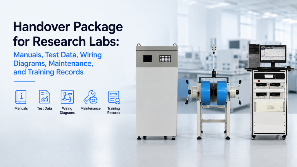
A research instrument is not fully delivered when the crates arrive or when the equipment completes its first successful test.
For a VSM, MOKE system, cryogenic platform, Hall Effect Measurement System, electromagnet, Helmholtz coil, or integrated Magnet & Field System, the laboratory must also receive enough information to:
- Install the system correctly
- operate it safely
- reproduce the acceptance tests
- identify every supplied component
- restore software and controller settings
- diagnose common faults
- perform routine maintenance
- train future users
- order replacement parts
- manage system modifications
- communicate efficiently with the supplier
That information should be organized into a formal research lab handover package.
A handover package is more than a user manual.
It is the complete technical record of the system as manufactured, tested, shipped, installed, configured, accepted, and transferred to the laboratory.
For complex scientific equipment, a strong handover package may include:
- Equipment and serial-number register
- final configuration list
- installation manuals
- operating manuals
- safety procedures
- wiring diagrams
- connector pinouts
- cooling and vacuum schematics
- mechanical drawings
- software and firmware versions
- configuration backups
- calibration records
- FAT and SAT reports
- raw test data
- maintenance schedules
- consumables and spare-parts lists
- troubleshooting procedures
- training materials
- attendance records
- punch-list status
- change history
- warranty and service information
This article explains what buyers should request before accepting a custom research system—and how suppliers can use a structured handover package to make installation, operation, service, and future upgrades more reliable.
1. Why the Handover Package Matters
Research systems often remain in service for many years.
During that time:
- The original buyer may change roles.
- Graduate students may leave.
- Laboratory technicians may be replaced.
- Computers may fail.
- Software may be reinstalled.
- Sensors may be changed.
- Cables may be disconnected.
- The system may be relocated.
- New experiments may be added.
- The original commissioning engineer may no longer be available.
Without a proper handover package, knowledge remains dependent on individual memory.
That creates operational risk.
A laboratory should be able to understand the delivered system even when the people involved in the purchase are no longer present.
2. A User Manual Is Only One Part of the Package
A standard user manual may explain:
- Basic startup
- normal operation
- shutdown
- menu functions
- common alarms
But it may not identify:
- The exact configuration supplied to this laboratory
- custom wiring
- final connector assignments
- installed sensor serial numbers
- calibration files
- project-specific software settings
- modified mechanical interfaces
- FAT test conditions
- site changes made during commissioning
- spare parts supplied
- training completed
The handover package should connect the generic product documentation with the actual delivered system.
3. The Package Should Describe the As-Delivered System
The key phrase is:
As delivered—not merely as originally proposed.
Custom systems often change between quotation and final acceptance.
Possible changes include:
- Different sensor model
- revised cable length
- updated connector
- modified sample holder
- changed power input
- additional interlock
- revised software
- different chiller
- updated pole geometry
- relocated temperature sensor
- new field calibration coefficient
The final handover package should reflect all approved changes.
An early proposal drawing should not be treated as the final system record unless it matches the delivered equipment.
4. Use a Master Handover Index
The package should begin with a master index.
The index may include:
| Document ID | Document Title | Revision | Date | File Name | Status |
|---|---|---|---|---|---|
| HP-001 | Final Configuration List | Rev. A | 2026-08-01 | HP-001_Config.pdf | Final |
| HP-002 | System User Manual | Rev. B | 2026-08-01 | HP-002_Manual.pdf | Final |
| HP-003 | Main Wiring Diagram | Rev. C | 2026-07-28 | HP-003_Wiring.pdf | As-built |
| HP-004 | FAT Report | Rev. A | 2026-07-20 | HP-004_FAT.pdf | Approved |
| HP-005 | FAT Raw Data | Rev. A | 2026-07-20 | HP-005_FAT_Data.zip | Approved |
The index helps users confirm:
- Which files should exist
- which revision is current
- which files are final
- which files are project-specific
- whether anything is missing
5. Create an Equipment and Serial-Number Register
The laboratory should receive a complete equipment register.
It may include:
- Main system model
- magnet model
- magnet serial number
- power-supply model and serial number
- temperature-controller model and serial number
- sensor model and serial number
- cryostat serial number
- vacuum-pump model and serial number
- chiller model and serial number
- gaussmeter and probe serial numbers
- computer serial number
- software-license identifier
- third-party component models
- supplied accessories
This register supports:
- Warranty claims
- calibration planning
- spare-parts ordering
- insurance
- asset registration
- future upgrades
6. Record the Final System Configuration
The final configuration list should identify:
- Base system
- options
- custom modifications
- excluded items
- buyer-supplied items
- third-party components
- firmware
- software modules
- sensor channels
- heater channels
- communication interfaces
- safety options
- supplied sample holders
- supplied pole sets
- supplied cables
- supplied consumables
This document should answer:
What exactly did the laboratory receive?
It should be detailed enough to prevent uncertainty several years later.
7. Separate Generic and Project-Specific Manuals
The package may contain two types of manuals.
Generic Product Manuals
Examples:
- Temperature-controller manual
- chiller manual
- vacuum-pump manual
- gaussmeter manual
- power-supply manual
Project-Specific Manuals
Examples:
- Integrated system operating sequence
- project-specific wiring
- magnet and cryostat alignment
- custom sample-holder instructions
- system startup order
- system shutdown order
- custom software workflow
Generic manuals explain individual components.
The project-specific manual explains how those components work together.
8. Installation Manual
The installation manual should cover:
- Crate inspection
- safe unpacking
- lifting points
- system weights
- center of gravity
- assembly sequence
- floor or table requirements
- leveling
- alignment
- electrical connection
- cooling connection
- vacuum connection
- gas connection
- network connection
- initial inspection
- pre-power checks
- required tools
- installation photographs
For modular Helmholtz systems and large electromagnets, the manual should also identify:
- Coil orientation
- axis labels
- polarity
- frame assembly
- coil spacing
- fastener torque
- cable routing
- magnetic center
9. Operating Manual
The operating manual should explain the normal workflow.
A useful structure includes:
- Pre-start inspection
- utility checks
- cooling startup
- vacuum startup
- controller startup
- power-supply startup
- software connection
- sample installation
- measurement setup
- normal operation
- controlled shutdown
- emergency shutdown
The manual should distinguish:
- Mandatory steps
- recommended steps
- optional steps
- prohibited actions
10. Quick-Start Guide
A full manual may be too long for daily operation.
A quick-start guide can provide:
- One-page startup checklist
- one-page shutdown checklist
- sample-loading sequence
- common settings
- emergency contact information
- warning limits
- basic fault checks
The quick-start guide should not replace the manual.
It should point users to the relevant detailed sections when a problem occurs.
11. Safety Documentation
Safety records may include:
- Electrical hazards
- high-current hazards
- magnetic-field hazards
- cryogenic hazards
- vacuum hazards
- compressed-gas hazards
- optical or laser hazards
- hot-surface hazards
- lifting hazards
- pinch points
- emergency-stop procedure
- interlock logic
- required personal protective equipment
- restricted-access boundaries
For magnetic systems, the package should identify risks to:
- Pacemakers
- magnetic tools
- watches
- phones
- storage media
- nearby instruments
- ferromagnetic objects
12. Wiring Diagrams
Wiring diagrams are among the most valuable handover documents.
They should show:
- Main power distribution
- magnet power connections
- control wiring
- sensor wiring
- heater wiring
- safety-interlock wiring
- emergency-stop circuit
- cooling-flow interlock
- vacuum interlock
- communication cables
- grounding
- shielding
- external interfaces
A diagram should identify actual terminal numbers and connector names—not only general blocks.
13. Connector Pinouts
Each custom or multi-pin connector should have a pinout.
The pinout may include:
| Pin | Signal | Direction | Maximum Rating | Cable/Wire | Notes |
|---|---|---|---|---|---|
| 1 | Sensor excitation + | Output | 1 mA | Twisted pair | Channel A |
| 2 | Sensor excitation − | Return | — | Twisted pair | Channel A |
| 3 | Sensor sense + | Input | 10 V max | Shielded | Channel A |
| 4 | Sensor sense − | Input | 10 V max | Shielded | Channel A |
Pinouts should also state:
- Connector manufacturer
- part number
- mating connector
- keying
- cable length
- shield connection
- unused pins
- reserved pins
14. Cable Identification
Every supplied cable should be identifiable.
Use:
- Cable number
- source connector
- destination connector
- cable length
- cable type
- current or voltage rating
- shielding
- bend-radius limit
- replacement part number
Cable labels should match the wiring diagrams.
A cable marked only “Cable A” becomes difficult to replace when the label is lost or damaged.
15. Grounding and Shielding Diagram
Low-noise Hall, VSM, MOKE, and cryogenic systems may require a dedicated grounding plan.
The handover package should show:
- Protective earth
- signal ground
- chassis ground
- shield termination
- magnet power-supply ground
- cryostat ground
- optical-table ground
- computer ground
- third-party instrument grounds
The diagram should identify whether shields are connected:
- At one end
- at both ends
- through the connector shell
- through a separate grounding point
This is valuable when diagnosing ground loops and electrical noise.
16. Cooling Circuit Diagram
For water-cooled magnets and power supplies, provide:
- Chiller outlet
- magnet inlet
- magnet outlet
- return line
- filter
- flow switch
- temperature sensor
- pressure gauge
- valves
- drain point
- hose size
- fitting type
- flow direction
The package should also state:
- Required flow
- pressure
- inlet temperature
- acceptable fluid
- filtration
- maintenance interval
- interlock threshold
17. Vacuum System Diagram
A vacuum-system diagram should identify:
- Chamber
- pump
- valves
- gauge
- vent valve
- purge connection
- hoses
- clamps
- seals
- exhaust
- permitted operating sequence
The diagram should show which components are:
- Vendor-supplied
- buyer-supplied
- replaceable
- safety-critical
For cryostats and probe stations, it should include normal pump-down and venting procedures.
18. Gas and Cryogen Connections
Where applicable, document:
- Gas type
- purity
- supply pressure
- regulator
- connection
- flow
- purge sequence
- exchange-gas procedure
- cryogen filling
- vent route
- safety requirement
Do not assume that future users will know which gas connection is intended for purge, process gas, exchange gas, or venting.
19. Mechanical Drawings
Mechanical documentation may include:
- Overall dimensions
- footprint
- mounting holes
- service clearance
- sample position
- field center
- cryostat insertion depth
- pole dimensions
- pole-gap range
- optical-axis height
- stage travel
- load limits
- interface dimensions
For buyer-designed fixtures, provide enough interface information for safe integration.
The supplier does not necessarily need to release proprietary manufacturing drawings, but usable interface drawings should be included.
20. Coordinate Systems and Orientation
Magnetic and optical systems need clear coordinate definitions.
Document:
- X, Y, and Z axes
- positive magnetic-field direction
- sample normal
- optical-beam direction
- rotation-axis direction
- power-supply polarity
- probe orientation
- software coordinate convention
This prevents mistakes when users compare:
- Positive and negative Hall voltage
- longitudinal and transverse MOKE
- clockwise and counterclockwise rotation
- positive and negative magnetic field
21. Software Installation Package
The software handover may include:
- Installer
- driver packages
- supported operating systems
- license information
- installation guide
- communication setup
- firewall requirements
- offline installation procedure
- administrator requirements
- recovery procedure
- release notes
The laboratory should know whether the software can be reinstalled if the original computer fails.
22. Software and Firmware Baseline
Record the accepted baseline:
- Application-software version
- firmware version
- instrument driver version
- operating-system version
- database version
- custom script version
- configuration-file version
- calibration-file version
NASA configuration-management guidance emphasizes identifying product configurations, controlling changes, maintaining traceability, and preserving configuration records throughout the product life cycle. This principle is directly relevant to research systems whose hardware, software, firmware, and documents must remain synchronized.
23. Configuration Backup
The handover package should contain backup copies of:
- Controller settings
- power-supply settings
- PID parameters
- temperature zones
- sensor curves
- heater limits
- field-current coefficients
- stage coordinates
- report templates
- user recipes
- communication settings
- software configuration
- license files, where permitted
The backup should include restoration instructions.
A backup that cannot be restored without undocumented vendor software provides limited protection.
24. Custom Sensor Curves
For cryogenic systems, record:
- Sensor model
- serial number
- calibration file
- controller curve slot
- assigned input channel
- valid temperature range
- excitation setting
- wiring method
- curve upload date
The physical sensor, certificate, file, controller slot, and channel assignment should be traceable to one another.
25. Calibration and Verification Records
The package should distinguish:
Calibration Certificate
A formal calibration record produced under a defined procedure.
Factory Verification Record
Evidence that a parameter was checked during production.
FAT Result
Evidence that the delivered system passed the agreed factory tests.
SAT Result
Evidence that the installed system passed agreed site tests.
Reference-Sample Result
A functional check using a known or characterized sample.
These documents should not be grouped under the vague title “calibration documents.”
26. FAT Report
The FAT report should identify:
- Equipment configuration
- test date
- participants
- test procedure
- test equipment
- test conditions
- acceptance criteria
- actual results
- pass/fail status
- deviations
- corrective actions
- raw-data references
- photographs or videos
It should also record the tested:
- Pole gap
- cooling condition
- load
- temperature
- field level
- sample
- software version
- sensor and probe
27. Raw FAT Data
Processed graphs alone may not be enough.
Depending on the system, buyers may request:
- Field-current data
- field maps
- current ripple
- field stability
- temperature logs
- cooldown curves
- vacuum logs
- heater output
- Hall voltage
- VSM loops
- MOKE loops
- background measurements
- sample-stage coordinates
- continuous-run temperature data
Provide data in a usable format such as:
- CSV
- TXT
- XLSX
- native system file
- image or PDF report
The original native file and an open data format can both be useful.
28. Record the Test Conditions
Every important test result should identify:
- Starting condition
- environmental condition
- equipment configuration
- test duration
- measurement position
- measurement instrument
- data-processing method
- software version
- applied corrections
- uncertainty or tolerance, where applicable
A field map without pole gap, current, coordinates, and probe information is difficult to reuse.
A cooldown curve without sample mass and wiring configuration may not represent future operation.
29. SAT and Commissioning Records
If site commissioning is performed, include:
- Site-readiness checklist
- installation inspection
- utility measurements
- startup checklist
- safety-interlock tests
- functional tests
- performance tests
- reference-sample results
- training completed
- punch-list items
- final acceptance status
The U.S. Department of Energy’s commissioning guidance treats functional testing, system documentation, operator training, findings, and corrective actions as connected parts of a structured commissioning process.
30. Reference-Sample Documentation
Where a reference sample is supplied, document:
- Sample ID
- material
- dimensions
- mass or thickness
- mounting method
- assigned or typical values
- measurement configuration
- storage method
- handling restrictions
- test procedure
The package should clarify whether the sample is:
- A certified reference material
- a calibrated standard
- a factory check sample
- a stable comparison sample
These terms should not be treated as identical.
31. System-Specific Test Procedures
The package should include procedures for repeating important checks.
Examples:
Electromagnet
- Coil resistance
- cooling flow
- polarity
- field-current curve
- field at center
Helmholtz Coil
- Axis identification
- polarity
- field constant
- center location
- background compensation
Hall System
- Contact check
- current reversal
- field reversal
- reference-sample measurement
Cryogenic System
- Vacuum check
- sensor check
- heater check
- cooldown
- stability check
VSM
- Empty-holder background
- sample centering
- reference-sample loop
32. Preventive Maintenance Schedule
The handover package should state:
- Maintenance task
- frequency
- responsible person
- required tools
- required consumables
- inspection criterion
- replacement criterion
- record to retain
Example:
| Task | Frequency | Responsibility | Record |
|---|---|---|---|
| Inspect cooling hoses | Monthly | User | Maintenance log |
| Clean chiller filter | Every 3 months | User | Filter record |
| Verify emergency stop | Every 6 months | Lab technician | Safety test form |
| Calibrate gaussmeter | As recommended | Calibration provider | Certificate |
| Service cryocooler | By operating hours | Authorized service | Service report |
33. Consumables List
Identify items expected to require replacement, such as:
- Probe tips
- O-rings
- filters
- fuses
- cooling fluid
- pump oil
- sample cards
- bonding wire
- vacuum grease
- thermal paste
- lamps
- batteries
- seals
- adhesives
For each item, provide:
- Part number
- specification
- quantity supplied
- expected replacement frequency
- approved alternative
- storage conditions
34. Spare-Parts List
Separate spare parts into categories.
Commissioning Spares
Items that should be available during installation.
Routine Spares
Parts likely to be used during normal maintenance.
Critical Spares
Parts that can stop the complete system and may have long lead times.
Optional Long-Term Spares
Parts appropriate for remote or difficult-to-service locations.
Possible examples include:
- Sensor
- cable
- control module
- fuse
- flow switch
- fan
- relay
- connector
- temperature-controller module
- vacuum gauge
- sample holder
35. Recommended Tools
Document any special tools required for:
- Pole replacement
- sample mounting
- cryostat seals
- vacuum connections
- cable replacement
- alignment
- torque control
- probe positioning
- maintenance
The list should distinguish:
- Tools supplied with the system
- standard laboratory tools
- optional vendor tools
- tools that must not be used
36. Troubleshooting Guide
A useful troubleshooting guide is symptom-based.
Example:
| Symptom | Possible Cause | User Check | Escalation |
|---|---|---|---|
| Magnet will not energize | Flow interlock open | Check chiller and flow | Contact vendor if flow is normal |
| Temperature unstable | Poor PID or sensor contact | Check heater and sensor | Send trend data |
| Vacuum pump-down slow | Seal contamination | Inspect O-ring | Leak test if unresolved |
| Hall voltage noisy | Ground loop or poor contact | Check wiring and sample | Provide raw data |
The guide should identify which checks are safe for users and which require vendor authorization.
37. Diagnostic Data Collection
The handover package should explain how to collect:
- Error logs
- screenshots
- configuration files
- current and voltage readings
- temperature logs
- vacuum readings
- field data
- photographs
- videos
- software logs
This reduces support delays.
Instead of exchanging several emails to identify basic information, the laboratory can submit a structured diagnostic package.
38. User-Serviceable and Factory-Service Boundaries
Clearly identify:
User-Serviceable
- Fuses
- approved cables
- filters
- O-rings
- sample holders
- software restoration
- routine cleaning
Vendor-Authorized Local Service
- Sensor replacement
- control-module replacement
- connector repair
- selected software updates
Factory Service
- Coil rewinding
- sealed cryostat repair
- high-power electronics repair
- precision-stage rebuild
- specialized recalibration
This protects both safety and warranty.
39. Training Plan
Training should be planned, not treated as an informal demonstration.
A training plan may include:
Operator Training
- Startup
- sample loading
- measurement
- shutdown
- data export
Advanced Training
- Method configuration
- PID tuning
- field sequences
- custom software
- raw-data analysis
Maintenance Training
- Inspection
- consumables
- backups
- common fault checks
Safety Training
- Emergency stop
- high current
- magnetic field
- vacuum
- cryogens
- lasers
40. Training Materials
The handover package may include:
- Training slides
- quick-start guide
- checklists
- example datasets
- example measurement recipe
- demonstration video
- recorded remote session
- maintenance guide
- practical exercises
- competency checklist
Training materials should be reusable for future laboratory staff.
A one-time verbal session is not a durable training system.
41. Training Attendance Records
Record:
- Date
- location
- trainer
- trainee names
- departments
- topics covered
- duration
- practical exercises completed
- questions or limitations
- signatures, where required
Training records can support:
- Laboratory safety
- internal authorization
- warranty discussions
- future refresher training
- institutional audits
42. Training Completion Does Not Equal Research-Method Development
The handover package should distinguish:
Equipment Training
How to operate the delivered system.
Application Development
How to design a new experiment, optimize a measurement method, or interpret complex scientific results.
Application development may be:
- Included in limited form
- available as an additional service
- outside the supplied scope
This boundary should be recorded during handover.
43. Acceptance Records
The final package may include:
- Signed FAT approval
- signed SAT approval
- commissioning report
- acceptance certificate
- conditional acceptance
- punch list
- deviation approvals
- corrective-action closure
- outstanding-item list
Acceptance should not depend only on an email stating:
“The system appears to work.”
The record should identify what was tested and what remains open.
44. Punch-List Register
A punch list should include:
| Item | Description | Priority | Responsible Party | Due Date | Closure Evidence |
|---|---|---|---|---|---|
| P-01 | Replace damaged cable label | Minor | Vendor | 2026-08-10 | Photo |
| P-02 | Upload revised sensor curve | Functional | Vendor | 2026-08-05 | Configuration file |
| P-03 | Provide updated drawing | Documentation | Vendor | 2026-08-07 | Rev. B drawing |
Minor documentation issues should be separated from faults that prevent normal operation.
45. Deviations and Approved Exceptions
If a delivered item differs from the original requirement, the record should state:
- Original requirement
- delivered condition
- reason for deviation
- technical impact
- commercial impact
- approval
- corrective action, if any
Do not let deviations remain hidden in emails.
They should be traceable in the final handover package.
46. Change History
After acceptance, the laboratory should continue recording changes such as:
- Sensor replacement
- software update
- firmware update
- cable replacement
- new sample holder
- changed PID settings
- changed field calibration
- relocated equipment
- modified cooling system
- added third-party instrument
NASA configuration-management guidance highlights the importance of controlling changes, maintaining configuration integrity, and preserving accurate records throughout the product life cycle.
The handover package should become the starting baseline for that ongoing record.
47. File Naming and Revision Control
Use consistent names.
A practical format is:
Project_DocumentType_DocumentNumber_Revision_Date
Example:
CryogenicHall_Wiring_HP003_RevC_20260801.pdf
Avoid names such as:
- Final.pdf
- Final2.pdf
- NewFinal.pdf
- LatestCorrected.pdf
Every revised file should show:
- Revision
- date
- author
- reason for change
- approval status
48. Final, Draft, and Superseded Status
Documents should be marked as:
- Draft
- For review
- Approved
- Final
- As-built
- Superseded
- Archived
Superseded files should not remain mixed with current operating documents without clear warning.
A technician using an obsolete wiring diagram can create a real safety or service problem.
49. Editable and Non-Editable Formats
The handover package may include:
Non-Editable Records
- Signed reports
- certificates
- approved drawings
- final manuals
Common format:
Editable Operational Files
- Data templates
- maintenance logs
- configuration tables
- spare-parts lists
- training attendance
- test worksheets
Common formats:
- XLSX
- CSV
- DOCX
- TXT
Native Technical Files
- Software configuration
- calibration curves
- instrument recipes
- CAD interface models
- system data
The quotation should state which editable or native files will be supplied.
50. Open Data Formats
When possible, provide key data in an open format.
Examples:
- CSV for test results
- PDF for signed reports
- STEP for mechanical interfaces
- TXT or CSV for sensor curves
- standard image formats for photographs
- documented JSON or XML for configuration exports
A proprietary native file may also be included, but it should not be the only available version of essential acceptance data.
51. Storage and Backup
The laboratory should store the handover package in at least two controlled locations.
Possible locations include:
- Laboratory server
- institutional document system
- asset-management system
- controlled external backup
- equipment computer
Do not keep the only copy on:
- One USB drive
- one engineer’s laptop
- an email inbox
- the original equipment computer
The equipment computer may eventually fail or be replaced.
52. Access Control
Some files may require controlled access.
Examples include:
- Administrator passwords
- software licenses
- remote-access credentials
- proprietary drawings
- service procedures
- safety settings
- source code
The laboratory should define:
- Who can view the files
- who can edit them
- who approves changes
- where passwords are stored
- how access is transferred when staff leave
53. Intellectual Property Boundaries
A buyer may need enough information to operate and maintain the system without receiving the supplier’s complete proprietary design.
The quotation should distinguish:
Normally Included
- User manuals
- interface drawings
- wiring diagrams
- connector pinouts
- operating procedures
- maintenance instructions
- accepted configuration
- test records
Potentially Restricted
- Full manufacturing drawings
- source code
- proprietary algorithms
- internal design calculations
- supplier component sourcing
- confidential process documents
The boundary should be agreed before purchase.
54. Cybersecurity and Software Recovery
For software-controlled systems, the package should cover:
- User accounts
- default passwords
- password-change procedure
- operating-system recovery
- software reinstallation
- license recovery
- network ports
- remote-support method
- backup frequency
- antivirus limitations
- update policy
The buyer should know whether operating-system updates can affect drivers or instrument communication.
55. Handover Package for VSM Systems
A VSM package may include:
- Magnet manual
- power-supply manual
- vibration-head manual
- pickup-coil information
- sample-holder drawings
- sample-centering procedure
- field-probe calibration
- empty-holder background
- reference-sample data
- moment verification
- software configuration
- temperature-option procedures
- maintenance schedule
- sample-rod and cup list
Raw VSM data should include enough information to reproduce:
- Field axis
- moment axis
- background subtraction
- calibration factor
- sample mass or volume
- data-processing method
56. Handover Package for MOKE Systems
A MOKE package may include:
- Optical layout
- laser or light-source manual
- detector information
- polarization configuration
- objective specification
- sample-position drawing
- magnet and power-supply data
- field calibration
- longitudinal, transverse, or polar configuration
- alignment procedure
- reference-sample images
- background and normalization method
- camera settings
- software recipes
- optical-safety records
Photographs of the accepted optical alignment can be particularly valuable after relocation or maintenance.
57. Handover Package for Cryogenic Systems
A cryogenic package may include:
- Cryostat manual
- vacuum diagram
- pump manuals
- sensor register
- sensor calibration curves
- controller configuration
- heater resistance
- PID settings
- cooldown curve
- base-temperature data
- stability data
- sample-holder drawings
- internal wiring
- feedthrough pinouts
- safe warm-up procedure
- venting and purge procedure
- compressor or cryogen requirements
- sample-exchange procedure
The package should state which internal components are user-accessible.
58. Handover Package for Electromagnets
An electromagnet package may include:
- Magnet dimensions
- weight
- pole drawings
- pole-gap limits
- coil resistance
- coil inductance
- insulation data
- cooling requirements
- hose and fitting information
- power-supply settings
- field-current curves
- maximum and continuous-duty conditions
- temperature-rise data
- polarity
- remanence and degaussing procedure
- field-probe location
- interlock diagram
Field data should identify the tested pole gap and pole set.
59. Handover Package for Helmholtz Coil Systems
A Helmholtz package may include:
- Frame assembly drawings
- coil dimensions
- pair spacing
- axis labels
- polarity
- coil constants
- resistance and inductance
- field center
- coordinate system
- current limits
- power-supply assignments
- cooling requirements
- field maps
- uniformity volume
- background-field measurements
- compensation procedure
- DUT mounting interface
- software configuration
For modular systems, include reassembly verification procedures.
60. Handover Package for Hall Systems
A Hall package may include:
- Magnet and power-supply documentation
- gaussmeter and probe data
- sample-holder pinout
- Hall-bar and van der Pauw procedures
- contact-check method
- current-reversal sequence
- field-reversal sequence
- sample-thickness entry
- calculation equations
- reference-sample result
- carrier type
- sheet resistance
- carrier concentration
- mobility
- raw-data format
- cryogenic option documentation
- software report template
The package should state the calculation assumptions used by the software.
61. Handover Package for Power Supplies
A power-supply package may include:
- Input requirement
- output current and voltage
- load compatibility
- quadrant operation
- current stability
- ripple
- accuracy
- resolution
- ramp-rate settings
- protection thresholds
- communication commands
- output cable specification
- grounding
- cooling
- calibration data
- load-test results
- emergency shutdown
- firmware version
For custom inductive loads, include the tested load or magnet parameters.
62. What Should Be Delivered Before Shipment?
Before shipment, the buyer may receive:
- Preliminary installation manual
- site-readiness guide
- crate dimensions and weights
- delivery-route requirements
- utility requirements
- interface drawings
- software requirements
- draft FAT protocol
- training plan
These documents allow the laboratory to prepare before the equipment arrives.
The final as-built documents can follow after FAT and commissioning.
63. What Should Be Delivered at FAT?
At FAT, provide or review:
- Final configuration list
- FAT procedure
- FAT report
- raw data
- photographs
- videos
- calibration records
- software version
- configuration backup
- open deviations
- preliminary manuals
The buyer should identify missing documents before shipment, when correction is easier.
64. What Should Be Delivered at Final Acceptance?
At final acceptance, the laboratory should receive:
- Final handover index
- as-built manuals
- as-built drawings
- final software baseline
- configuration backup
- FAT and SAT records
- closed or agreed punch list
- training records
- maintenance schedule
- spare-parts list
- warranty details
- support contacts
Final payment or acceptance may be linked to completion of agreed documentation, depending on the contract.
65. Better RFQ Language
Instead of writing:
“Please include all manuals and documents.”
write:
“Please include a complete research lab handover package covering the as-delivered system configuration, equipment and serial-number register, installation manual, operating manual, safety procedures, electrical wiring diagrams, connector pinouts, grounding and shielding diagrams, cooling and vacuum schematics, mechanical interface drawings, software and firmware versions, configuration backups, calibration records, FAT/SAT reports, raw test data, maintenance schedule, consumables, spare parts, troubleshooting procedures, training materials, training attendance records, deviations, punch-list status, and warranty/service information.
Please provide a master document index identifying each file, revision, date, format, and final approval status. Project-specific as-built documentation shall take precedence over earlier proposal drawings.”
66. Better Quotation Language
“The quoted system includes a digital handover package supplied before final acceptance.
The package will include:
- Final equipment and serial-number list
- as-built configuration
- user and installation manuals
- project-specific wiring and interface drawings
- connector pinouts
- cooling and vacuum schematics
- software, firmware, and configuration baseline
- configuration backup
- FAT report and agreed raw test data
- calibration and verification records
- maintenance and troubleshooting information
- consumables and spare-parts lists
- training materials and attendance records
- final punch-list and deviation status
- warranty and support procedures
Proprietary manufacturing drawings, source code, and internal design calculations are excluded unless expressly listed.”
67. Handover Package Comparison Matrix
Buyers can compare suppliers using this matrix:
| Handover Item | Supplier A | Supplier B | Supplier C |
|---|---|---|---|
| Master document index | Included | Not stated | Included |
| As-built configuration | Included | Proposal only | Included |
| Wiring diagrams | Detailed | Block diagram | Detailed |
| Connector pinouts | Included | Not stated | Included |
| FAT raw data | CSV + native | PDF graph only | CSV |
| Configuration backup | Included | Not stated | Optional |
| Maintenance schedule | Included | Basic | Included |
| Training records | Included | No | Included |
| As-built revision after SAT | Included | Optional | Included |
| Proprietary-file exclusions | Clear | Not stated | Clear |
This prevents documentation quality from being treated as an afterthought.
68. Common Buyer Mistakes
Mistake 1: Asking Only for a User Manual
A manual does not replace as-built drawings, test data, or configuration backups.
Mistake 2: Accepting Proposal Drawings as Final Records
The delivered configuration may have changed.
Mistake 3: Receiving Graphs Without Raw Data
Future users cannot easily reprocess or verify the results.
Mistake 4: Ignoring Software and Firmware Versions
Reinstallation may produce a different operating configuration.
Mistake 5: Not Backing Up Custom Settings
PID parameters, sensor curves, and field coefficients may be difficult to reconstruct.
Mistake 6: Not Requesting Connector Pinouts
Cable repair and system integration become unnecessarily difficult.
Mistake 7: Treating Training as a Verbal Demonstration
Future users need reusable materials and records.
Mistake 8: Not Separating Current and Superseded Documents
An obsolete drawing can create maintenance errors.
Mistake 9: Not Recording Site Modifications
The documentation no longer matches the installed system.
Mistake 10: Waiting Until Final Payment to Discuss Documentation
Required deliverables should be agreed in the quotation or purchase order.
69. How Cryomagtech Supports Complete Research Lab Handover Packages
Cryomagtech supplies electromagnets, Helmholtz coils, magnetic field power supplies, Hall Effect Measurement Systems, VSM-related systems, MOKE systems, cryogenic temperature controllers, monitors, cryostats, field probes, and custom Magnet & Field Systems.
For documentation-intensive projects, we help buyers define:
- Final configuration records
- equipment and serial-number registers
- installation and operating manuals
- project-specific wiring diagrams
- connector and feedthrough pinouts
- grounding and shielding
- cooling and vacuum diagrams
- sample-holder interfaces
- software and firmware baselines
- sensor curves and controller settings
- configuration backups
- FAT and SAT reports
- raw test data
- field maps
- reference-sample records
- maintenance schedules
- consumables and spare parts
- troubleshooting procedures
- training materials
- attendance records
- punch-list closure
- warranty and service processes
A professional delivery is not complete when the equipment works only in front of the supplier’s engineer.
It is complete when the laboratory has the equipment, records, knowledge, files, and procedures needed to operate, maintain, verify, and support the system after the project team has left.
References
- U.S. Department of Energy — Commissioning Process for Federal Facilities
https://www.energy.gov/cmei/femp/commissioning-process-federal-facilities - NASA — Configuration Management
https://www.nasa.gov/reference/6-5-configuration-management/
Key Takeaways
- A research lab handover package is more than a user manual.
- It should describe the final as-delivered and as-installed system.
- A master index should identify every document, revision, date, format, and status.
- Equipment models, serial numbers, options, third-party components, and buyer-supplied items should be recorded.
- Project-specific wiring diagrams, connector pinouts, grounding, cooling, vacuum, and mechanical interfaces are essential.
- FAT and SAT records should include test conditions, acceptance criteria, results, deviations, and supporting raw data.
- Software, firmware, drivers, calibration files, sensor curves, and configuration settings should have a documented baseline.
- Configuration backups should be supplied with restoration instructions.
- Maintenance schedules should identify tasks, intervals, responsibilities, consumables, tools, and retained records.
- Training should include reusable materials, attendance records, and a clear distinction between operation and application development.
- Punch-list items, approved deviations, and corrective actions should remain traceable.
- Current, superseded, draft, approved, and as-built documents should be clearly identified.
- Key data should be supplied in practical open formats as well as relevant native formats.
- The handover package should become the starting baseline for future configuration and change records.
- Documentation requirements should be agreed in the quotation—not negotiated after final acceptance.
For custom research equipment delivery, the key question is not only:
“Will the supplier provide a manual?”
The better question is:
“Will the laboratory receive a complete, accurate, and recoverable technical record of the delivered system, its test evidence, wiring, software, maintenance needs, training, and future service requirements?”