
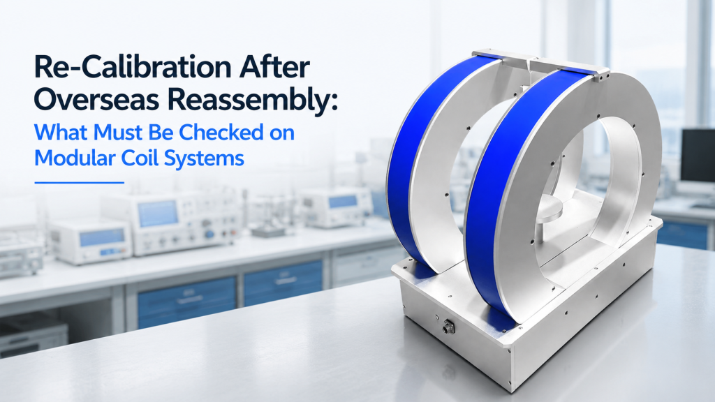
Large modular coil systems are often shipped overseas in separate sections.
This is normal.
A large three-axis Helmholtz coil, magnetic field calibration cage, sensor validation platform, or custom coil system may be too large to ship as one complete assembled unit. The system may need to be disassembled, packed into crates, transported internationally, unpacked, mechanically reassembled, wired, leveled, aligned, and verified again at the buyer’s site.
But after overseas reassembly, one question becomes very important:
Can the laboratory use the original factory calibration data directly, or must the system be checked again on site?
For serious magnetic field work, the answer is clear:
The system should be verified after reassembly.
Depending on the project scope, this may be called re-calibration, site verification, Site Acceptance Testing, field mapping, or installation verification. The exact term depends on the contract and measurement requirement.
This article explains what must be checked after overseas reassembly of a modular coil system, especially for large Helmholtz coil systems, three-axis calibration platforms, and magnetic field test systems used for magnetometers, IMUs, electronic compasses, sensors, and research equipment.
1. Why Modular Coil Systems Are Reassembled Overseas
Large coil systems are often modular because of practical export constraints.
A complete assembled coil structure may be:
- Too large for standard air freight
- too wide for doors or elevators
- too fragile if shipped fully assembled
- too heavy for one crate
- difficult to protect from vibration
- expensive to transport as one piece
- impractical for final laboratory positioning
Modular design makes international delivery more realistic.
The system may be separated into:
- X-axis coil pair
- Y-axis coil pair
- Z-axis coil pair
- mechanical frame sections
- base supports
- control cabinet
- power supplies
- field probes
- cables
- fixtures
- safety enclosure
- alignment accessories
However, modular shipping creates one unavoidable task:
The installed system must be checked after reassembly.
2. Factory Calibration Is Not Always the Final Installed Condition
A system may be tested at the factory before shipment.
That is useful.
Factory testing can confirm:
- Coil electrical continuity
- power supply function
- software operation
- basic field output
- polarity
- approximate field-current relationship
- mechanical completeness
- packing condition
But the factory test environment is not the final laboratory site.
After transport and reassembly, several things may change:
- Coil spacing
- axis alignment
- frame squareness
- cable routing
- grounding
- local magnetic background
- mechanical level
- field probe position
- power-supply wiring
- sensor coordinate definition
- fixture position
- environmental magnetic noise
For modular systems, factory data should be treated as a strong reference, not as automatic proof that the final installed system still performs identically.
3. Helmholtz Coil Field Quality Depends on Geometry
A Helmholtz coil is designed to generate a nearly uniform magnetic field near the center when the coil geometry and current conditions are correct.
The University of Surrey describes a Helmholtz coil facility using three pairs of parallel electromagnetic coils mounted in orthogonal X, Y, and Z directions to create a nearly uniform magnetic field inside an experimental control volume.
This is exactly why geometry matters.
For a modular coil system, field quality depends on:
- Coil spacing
- coil parallelism
- coil center alignment
- axis orthogonality
- frame rigidity
- current direction
- cable routing
- local environment
If the frame is reassembled slightly differently, the field at the center may still exist, but the qualified uniform-field volume may shift or degrade.
4. Re-Calibration Does Not Always Mean Full Factory Rebuild
Some buyers hear “re-calibration” and assume it means the entire system must be professionally recalibrated from zero.
Not always.
After overseas reassembly, the required work may range from simple verification to full recalibration.
Basic Site Verification
Confirms:
- Correct assembly
- correct wiring
- correct polarity
- basic field output
- software communication
- safety functions
- rough agreement with factory data
Field Verification
Checks:
- Field-current relationship
- zero-field condition
- positive and negative field output
- repeatability
- selected center and offset points
Field Mapping
Measures:
- Uniformity over a defined region
- X/Y/Z components
- spatial variation
- axis cross-coupling
- coordinate alignment
Formal Re-Calibration
May include:
- Calibrated reference instruments
- uncertainty statement
- defined procedure
- traceability chain
- complete calibration report
- repeated measurements
- controlled environmental conditions
The correct level depends on the buyer’s application and the agreed acceptance basis.
5. Traceability and Fitness for Purpose Are Different
For serious calibration projects, buyers may ask whether the field measurement is traceable.
NIST defines metrological traceability as a property of a measurement result related to a reference through a documented unbroken chain of calibrations, each contributing to measurement uncertainty. NIST also emphasizes that traceability alone does not guarantee fitness for purpose; the uncertainty must be small enough for the intended measurement need.
This matters for modular coil systems.
A field probe may be traceably calibrated, but the system still needs to be installed correctly.
Traceability of the probe does not automatically verify:
- Coil geometry
- field uniformity
- DUT positioning
- axis alignment
- background field
- cable effects
- fixture repeatability
Good site verification combines calibrated measurement tools with a clear system-level procedure.
6. What Can Change During Overseas Transport
Even well-packed equipment can experience changes during international shipment.
Possible transport-related changes include:
- Frame shift
- loose fasteners
- connector loosening
- cable strain
- cosmetic damage
- coil deformation
- insulation damage
- sensor displacement
- alignment-pin damage
- packing vibration
- moisture exposure
- missing accessories
- labeling confusion
Most shipments arrive safely.
But a modular coil system should not be judged only by appearance.
A system can look fine and still require re-verification of field performance.
7. What Can Change During Site Reassembly
Reassembly is often more important than shipping.
The site team may need to:
- Install coil frames
- align coil pairs
- connect axis cables
- mount power supplies
- route sensor cables
- install control software
- connect safety interlocks
- position the DUT fixture
- verify grounding
- level the frame
- define the coordinate system
Small mechanical differences can affect magnetic results.
For example:
- One coil pair may be slightly offset.
- X and Y axes may not be perfectly orthogonal.
- Cable polarity may be reversed.
- The DUT fixture may not sit at the original center.
- The field probe may be positioned differently from factory testing.
This is why site checks are not optional for serious systems.
8. Visual Inspection Comes First
Before applying current, inspect the assembled system.
Check:
- Crate damage
- coil frame condition
- coil winding damage
- connector condition
- missing screws
- loose fasteners
- alignment pins
- support brackets
- frame level
- cable labels
- cable strain relief
- cooling hardware, if any
- safety covers
- control cabinet
- emergency stop
- grounding points
Do not start field testing until the physical installation looks correct.
A visual inspection can catch many simple problems before they become electrical or magnetic problems.
9. Mechanical Geometry Must Be Checked
For modular coil systems, geometry is the heart of performance.
Check:
- Coil spacing
- coil pair parallelism
- coil centerline
- axis intersection
- frame squareness
- verticality
- support height
- base level
- fixture center
- probe access
- working volume location
For three-axis systems, also check:
- X-axis coil pair alignment
- Y-axis coil pair alignment
- Z-axis coil pair alignment
- orthogonality among axes
- distance from frame references to field center
- consistency with drawings
If the mechanical references are not restored, the factory field map may no longer represent the installed system.
10. The Magnetic Center Must Be Reconfirmed
The magnetic center is where the field is intended to be most useful.
After reassembly, confirm where that center is relative to:
- Coil frame
- fixture mounting plate
- DUT holder
- rotation stage
- reference probe
- sample table
- enclosure
- coordinate markers
A common mistake is assuming that the geometric center of the visible frame is exactly the calibrated field center.
For large modular systems, this assumption should be verified.
11. Uniformity Volume Must Be Tied to the Reassembled Geometry
A buyer may purchase a system based on a defined uniform-field volume.
For example:
- 50 mm cube
- 100 mm cube
- 300 mm diameter sphere
- DUT rotation envelope
- sensor calibration region
After reassembly, the supplier and buyer should confirm that this volume is still correctly located.
The system should not only generate field at one center point.
It should maintain the agreed field quality across the usable region.
For calibration systems, the real question is:
Does the reassembled system still meet the required field performance where the DUT is actually installed?
12. Electrical Continuity and Resistance Check
Before field operation, check each coil channel.
Useful checks include:
- Continuity
- insulation condition
- coil resistance
- connector polarity
- cable labels
- terminal tightness
- short circuit
- open circuit
- ground fault
- power supply output channel
- axis assignment
Compare resistance values with factory records when available.
A significant difference may indicate:
- Wrong wiring
- poor connection
- damaged cable
- loose terminal
- temperature difference
- measurement method difference
Do not drive high current into an uncertain coil circuit.
13. Confirm Coil Polarity Before Full Operation
Polarity mistakes are common after reassembly.
For each axis, apply a small safe current and measure the field direction.
Check:
- X positive command produces X positive field.
- Y positive command produces Y positive field.
- Z positive command produces Z positive field.
- negative command reverses correctly.
- no axis is swapped.
- no coil pair is wired against itself.
For a Helmholtz pair, both coils in the pair should support the intended field direction.
If one coil is reversed, the pair may create a gradient-like field instead of a uniform field.
14. Axis Assignment Must Be Verified
In a three-axis system, the software may show X, Y, and Z commands.
But after reassembly, cables may be connected incorrectly.
Axis errors may include:
- X and Y swapped
- Z polarity reversed
- one coil disconnected
- one power-supply channel assigned incorrectly
- field probe axes mislabeled
- coordinate system mismatch between software and fixture
Axis-by-axis testing should be performed before vector-field operation.
Do not start with a combined 3D vector command.
Start simple.
15. Power Supply and Driver Settings Must Match the Coil
After reassembly, verify the power-chain configuration.
Check:
- Current limit
- voltage limit
- ramp rate
- polarity mode
- output enable logic
- remote/local mode
- communication interface
- emergency stop behavior
- interlock status
- cooling requirement
- driver-channel mapping
- software calibration table
A modular coil system may use several matched power channels.
If the wrong channel drives the wrong axis, the field result may be incorrect even though every device powers on.
16. Cable Routing Can Affect Field and Noise
Cable routing after reassembly may differ from factory setup.
This can affect:
- Magnetic background
- induced noise
- field probe readings
- triboelectric noise
- sensor wiring
- sample access
- rotation clearance
- signal repeatability
- grounding loops
Large coil systems often have high-current cables near sensitive measurement cables.
Separate them where possible.
Keep cable loops controlled.
Use the intended cable supports and strain relief.
Document the final routing if it affects calibration.
17. Local Magnetic Environment Must Be Checked
The overseas site may have a different magnetic environment from the factory.
Possible sources include:
- Earth’s field
- building steel
- reinforced concrete
- elevators
- motors
- transformers
- power cables
- steel tables
- tools
- nearby magnets
- electric vehicles or traffic
- laboratory equipment
For low-field calibration systems, environmental background can be significant.
Record the background field before energizing the coils.
If the system includes background compensation, verify the compensation method on site.
18. Zero-Field Condition Must Be Checked
A zero-field check should be performed before calibration.
Measure:
- Ambient field with coil current off
- residual field after positive operation
- residual field after negative operation
- field probe zero
- noise and drift
- X/Y/Z background components
For air-core Helmholtz coils, residual magnetism is usually less of a concern than for iron-core electromagnets, but background field and nearby magnetic materials still matter.
Zero-field data provides the baseline for all later field measurements.
19. Field-Current Relationship Must Be Verified
The installed system should be checked at multiple setpoints.
For each axis, measure field at:
- Zero
- low positive current
- medium positive current
- high positive current
- low negative current
- medium negative current
- high negative current
Record:
- Current setpoint
- current readback
- measured field
- field direction
- probe position
- waiting time
- temperature
- background correction method
Compare with factory data or expected field constants.
A small difference may be acceptable if it is explained by environment, probe placement, or uncertainty.
A large difference needs investigation.
20. Do Not Verify Only the Maximum Field
Maximum field is important, but it is not enough.
A modular coil system may reach maximum field while still having:
- Wrong axis orientation
- poor linearity
- unexpected offset
- reduced uniformity
- swapped coordinates
- local magnetic contamination
- field-center shift
Check both low-field and high-field performance.
For sensor calibration systems, low-field accuracy may be more important than peak field.
21. Linearity Check Helps Identify Assembly Problems
For air-core coil systems, the field-current relationship is often expected to be reasonably linear within the operating range.
A basic linearity check can reveal:
- Wrong coil connection
- current readback error
- background subtraction error
- probe orientation problem
- unexpected magnetic material near the field volume
- power supply scaling problem
The test does not need to replace full calibration.
It provides an early warning that the reassembled system may not match the intended behavior.
22. Repeatability Must Be Checked
A system may produce the correct field once but fail to repeat.
Repeatability checks may include:
- Same current repeated several times
- ramp up from zero repeatedly
- positive-to-zero-to-positive cycles
- positive-to-negative-to-positive cycles
- axis switching
- vector-field commands
- rechecking after fixture movement
Record whether the measured field returns within the agreed tolerance.
Repeatability is especially important for calibration workflows.
23. Axis Orthogonality Must Be Verified
Three-axis coil systems need more than three independent fields.
The axes should be correctly oriented relative to each other.
After reassembly, verify:
- X, Y, and Z directions
- cross-axis components
- axis orthogonality
- coordinate convention
- software axis signs
- DUT fixture orientation
If the X-axis command also produces a significant Y or Z component, the issue may be:
- Mechanical misalignment
- probe misorientation
- coil geometry error
- environmental field
- software transformation error
For high-accuracy calibration, orthogonality should be part of acceptance.
24. Cross-Axis Coupling Should Be Measured
When one axis is energized, measure all three field components if possible.
Example:
- Command X field.
- Measure Bx, By, and Bz.
- Command Y field.
- Measure Bx, By, and Bz.
- Command Z field.
- Measure Bx, By, and Bz.
This helps identify:
- Axis tilt
- wiring errors
- reference-probe orientation problems
- frame distortion
- background-field projection
- coordinate mismatch
Cross-axis coupling may be small, but for magnetometer and IMU calibration it can matter.
25. Field Uniformity Mapping After Reassembly
If the purchased system includes a uniformity requirement, field mapping may be needed after reassembly.
Mapping should define:
- Mapping volume
- grid spacing
- coordinate system
- probe type
- probe orientation
- field level
- current setpoint
- background correction
- measurement uncertainty
- environmental condition
- pass/fail definition
The field map should cover the actual qualified volume, not only an empty space unrelated to the DUT fixture.
26. Full 3D Mapping vs. Practical Spot Checks
Not every project needs full 3D re-mapping on site.
The level depends on the application.
Practical Spot Check May Be Enough When
- The system is simple.
- factory mapping is available.
- site installation follows fixed references.
- the buyer needs basic functional verification.
- calibration accuracy is moderate.
Full 3D Mapping Is Better When
- The system is used for formal calibration.
- the uniformity tolerance is tight.
- the system was heavily disassembled.
- the frame is large.
- the DUT volume is large.
- acceptance depends on site performance.
- installation environment may affect results.
The contract should define which level is required.
27. Reference Probe Placement Matters
The field probe must be placed correctly.
Check:
- Probe active area
- probe axis direction
- probe calibration range
- probe mounting repeatability
- probe distance from center
- probe cable movement
- probe holder material
- probe temperature sensitivity
- field component measured
A calibrated probe in the wrong position does not verify the right field.
For three-axis systems, a triaxial probe can be useful, but its coordinate alignment must still be controlled.
28. Calibration Table and Software Constants Must Be Reviewed
A modular coil system may use software constants such as:
- Field-per-ampere coefficient
- X/Y/Z correction matrix
- background compensation values
- axis polarity
- coil geometry parameters
- field limits
- current limits
- ramp settings
- fixture coordinates
- calibration file names
After reassembly, verify that the software uses the correct configuration.
A wrong calibration file can make a physically good system produce wrong commanded fields.
29. Safety Interlocks Must Be Rechecked
Site reassembly can affect safety wiring.
Check:
- Emergency stop
- door interlock
- cooling interlock
- overtemperature protection
- power supply fault output
- output enable logic
- grounding
- warning lamps
- software safety limits
- cable covers
- mechanical guards
Do not assume safety functions survived shipment and reassembly unchanged.
A safe system should fail safely under defined fault conditions.
30. Cooling and Thermal Behavior Must Be Verified
Some coil systems require cooling, especially for high current or continuous duty.
After reassembly, check:
- Fan direction
- air path
- water inlet and outlet
- flow rate
- pressure
- chiller setting
- leak condition
- temperature sensors
- thermal interlocks
- coil temperature during operation
- power supply cooling
A coil may pass a short electrical test but fail during long-duration operation if cooling is incorrect.
If continuous operation is part of the scope, the site test should include a meaningful thermal run.
31. Grounding and Shielding Must Be Reviewed
Overseas laboratories may have different grounding and electrical infrastructure.
Check:
- Protective earth
- instrument ground
- signal ground
- shield termination
- cabinet grounding
- power supply grounding
- cable shields
- ground loops
- noise on field probe output
- communication stability
Poor grounding can create unstable readings, communication faults, or safety concerns.
For sensitive calibration systems, grounding should be part of the site verification procedure.
32. DUT Fixture Position Must Be Verified
The calibration system is only useful if the DUT is placed correctly.
Check:
- Fixture center
- sensor location
- rotation axis
- mounting repeatability
- non-magnetic hardware
- cable strain relief
- fixture orientation
- reference marks
- coordinate labels
- clearance during rotation
If the fixture is installed after field mapping, the fixture should not move the DUT outside the qualified volume.
For magnetometer and IMU calibration, fixture position is often as important as the coil field itself.
33. Magnetic Cleanliness After Installation
The local installation may introduce magnetic materials near the coil center.
Check for:
- Steel tools left inside the frame
- magnetic screws
- steel brackets
- magnetic fixtures
- speakers
- motors
- clamps
- phones
- laptops too close to the test volume
- magnetized probes
- nearby permanent magnets
A field map performed at the factory cannot account for a magnetic wrench left near the DUT holder.
Magnetic cleanliness should be part of the site checklist.
34. Reassembly Documentation Should Be Revision-Controlled
The final installed condition should be documented.
Record:
- Serial numbers
- assembly photos
- coil orientation
- cable connections
- software version
- calibration file version
- field probe serial number
- site test date
- operator
- environmental condition
- background field
- field-current data
- mapping results
- deviations
- corrective actions
Documentation prevents later confusion.
If the system is moved or serviced, the reassembly baseline can be used for comparison.
35. Compare Site Data with Factory Data Carefully
Factory and site data may not match perfectly.
Differences may come from:
- Probe position
- probe calibration
- background field
- measurement grid
- temperature
- cable routing
- frame leveling
- local magnetic materials
- different current readback
- software version
Do not compare only final numbers without comparing methods.
A useful comparison should ask:
- Was the same probe used?
- Was the same coordinate system used?
- Was background subtracted?
- Was the same field level tested?
- Was the same grid spacing used?
- Was the fixture installed?
- Were uncertainty and repeatability considered?
A difference may be acceptable if it is understood and within the agreed tolerance.
36. Site Acceptance Should Be Based on Agreed Scope
Before shipment, the buyer and supplier should define what happens after reassembly.
Site acceptance may include:
- Assembly inspection
- electrical continuity
- polarity test
- axis verification
- field-current check
- uniformity spot check
- full mapping
- safety test
- software test
- logging test
- fixture test
- thermal run
- training
If full re-calibration is required, it should be included in the quotation or service plan.
If only remote-guided verification is included, the buyer should understand that boundary.
Service scope should not be discovered after the equipment arrives.
37. Remote Support Can Work If Evidence Is Clear
For overseas modular coil systems, remote support can be effective when the buyer provides:
- Photos of assembly
- wiring photos
- screenshots
- field probe readings
- current readback data
- background field readings
- videos of software operation
- fault logs
- measurement files
- test checklist results
Remote support is not guessing.
It depends on structured evidence.
A well-designed reassembly checklist makes remote support much more efficient.
38. When On-Site Commissioning Is Worth Considering
On-site support may be appropriate when:
- The system is large or complex.
- field uniformity tolerance is tight.
- the system is used for formal calibration.
- full 3D mapping is required.
- the buyer has limited technical staff.
- mechanical alignment is difficult.
- safety requirements are strict.
- the project is high value.
- schedule risk is high.
- remote support is not enough for acceptance.
On-site commissioning is not always necessary, but for large modular systems it may reduce risk.
39. What Buyers Should Ask Before Ordering
Before buying a modular coil system, buyers should ask:
Shipment and Reassembly
- Will the system ship fully assembled or modular?
- Which parts will be removed?
- What alignment references are included?
- What tools are required?
- Who performs reassembly?
- Is on-site commissioning included or optional?
Verification
- What factory test data is provided?
- What must be checked after reassembly?
- Is field mapping required on site?
- What field probe is required?
- Who provides the probe?
- What uncertainty is expected?
Software
- Are calibration files provided?
- How are X/Y/Z constants stored?
- Can settings be backed up?
- Can site data be imported?
- Is logging included?
Acceptance
- Is SAT required?
- What is the pass/fail basis?
- Is remote SAT allowed?
- What documents must be signed?
- What happens if site data differs from factory data?
These questions prevent misunderstandings.
40. Practical Reassembly Verification Checklist
After reassembly, check the following.
Mechanical
- Frame level
- coil spacing
- coil parallelism
- axis alignment
- fixture center
- fastener tightness
- working volume clearance
Electrical
- Continuity
- resistance
- polarity
- channel assignment
- grounding
- power supply limits
- communication
Magnetic
- Background field
- zero-field condition
- axis direction
- field-current relationship
- repeatability
- cross-axis components
- selected uniformity points
- full mapping, if required
Software
- Correct calibration file
- axis labels
- polarity signs
- current limits
- field limits
- logging
- recipe settings
- data export
Safety
- Emergency stop
- interlocks
- cooling
- temperature sensors
- warning lights
- fault behavior
- safe shutdown
Documentation
- Site photos
- test data
- deviations
- corrective actions
- final acceptance record
This checklist should be adapted to the actual project.
41. Common Buyer Mistakes
Mistake 1: Assuming Factory Calibration Applies Automatically After Reassembly
Factory data is important, but site installation must still be checked.
Mistake 2: Checking Only Center Field
Uniformity, axis alignment, and DUT fixture position may still be wrong.
Mistake 3: Ignoring Background Field
The local magnetic environment can strongly affect low-field systems.
Mistake 4: Trusting Software Labels Without Testing Axis Direction
X, Y, and Z should be verified physically.
Mistake 5: Using a Calibrated Probe Incorrectly
A calibrated probe must still be placed and oriented correctly.
Mistake 6: Skipping Safety Interlock Tests
Safety wiring may change during reassembly.
Mistake 7: Not Saving Site Baseline Data
Future troubleshooting becomes harder without a site baseline.
Mistake 8: Confusing Remote Support with No Verification
Remote support still requires a structured verification process.
42. How Cryomagtech Supports Modular Coil Reassembly and Re-Calibration
Cryomagtech supplies modular Helmholtz coil systems, three-axis magnetic field platforms, excitation power supplies, field sensors, control software, fixtures, and custom Magnet & Field Systems for overseas research and calibration projects.
For modular coil systems requiring overseas shipment and reassembly, we help evaluate:
- Modular shipping structure
- assembly references
- coil spacing and axis alignment
- field-center definition
- X/Y/Z wiring and polarity
- background field measurement
- field-current verification
- uniformity spot checks
- full field mapping requirements
- calibration-file review
- fixture and DUT positioning
- safety interlock checks
- remote or on-site commissioning scope
- site acceptance checklist
- re-calibration documentation
A modular coil system should not be accepted only because it was successfully powered on.
After overseas reassembly, the important question is whether the installed system still creates the specified field at the correct location, with the correct direction, uniformity, repeatability, safety, and documentation.
References
- University of Surrey – Helmholtz Coil Facility
https://www.surrey.ac.uk/surrey-space-centre/facilities/helmholtz-coil - NIST – Policy on Metrological Traceability
https://www.nist.gov/calibrations/traceability - NIST – Metrological Traceability: Frequently Asked Questions and NIST Policy
https://www.nist.gov/metrology/metrological-traceability - Wikipedia – Helmholtz Coil
https://en.wikipedia.org/wiki/Helmholtz_coil
Key Takeaways
- Modular coil systems often require overseas reassembly because large Helmholtz and three-axis coil platforms are difficult to ship fully assembled.
- Factory calibration data is valuable, but it may not fully represent the final installed site condition after disassembly, transport, and reassembly.
- Re-calibration after overseas reassembly may range from basic site verification to full 3D field mapping, depending on the application.
- Mechanical geometry, coil spacing, axis alignment, polarity, field-current relationship, background field, fixture position, and software calibration files must all be checked.
- A calibrated field probe is useful only when its position, orientation, range, and uncertainty are controlled.
- Three-axis systems require axis-by-axis testing and cross-axis component checks.
- Safety interlocks, cooling, grounding, and software limits should be rechecked after installation.
- Site verification data should be saved as the installed baseline for future maintenance, troubleshooting, and audits.
- Remote support can be effective if the buyer provides structured photos, measurements, logs, and checklist results.
- On-site commissioning may be worth considering for large, tight-tolerance, formal-calibration, or high-value modular systems.
For modular coil system delivery, the key question is not only:
“Did the system pass factory testing before shipment?”
The better question is:
“After overseas reassembly, does the installed system still meet the agreed magnetic, mechanical, electrical, software, safety, and acceptance requirements at the buyer’s site?”