
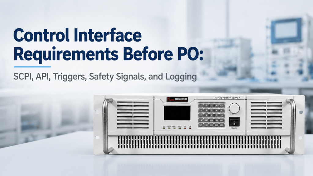
“Programmable control” sounds simple.
But in real engineering labs, automation projects often fail because the buyer and supplier never define what “programmable” actually means before the purchase order.
For an excitation power supply, magnetic field driver, Helmholtz coil system, electromagnet, Hall measurement system, cryogenic platform, or complete magnetic test rig, the control interface is not just a software feature.
It affects:
- Automation workflow
- safety logic
- data logging
- synchronization
- remote operation
- integration with third-party instruments
- acceptance testing
- long-term maintainability
Before issuing a PO, buyers should confirm the control interface requirements clearly: SCPI, API, communication port, trigger input/output, safety interlock, emergency stop, status feedback, logging, and documentation.
This article explains what engineering buyers should check before ordering a programmable magnet system or high-precision excitation power supply.
1. “Programmable” Is Not a Complete Specification
Many quotations say:
“Software control supported.”
“Remote interface available.”
“Programmable power supply.”
“API optional.”
“Computer control supported.”
These phrases are not enough.
A programmable instrument may support only basic setpoint control. Another system may support full sequence automation, real-time triggers, safety interlocks, status reporting, data logging, and external software integration.
Both suppliers may use the word “programmable.”
The real difference is in the interface details.
Weak Requirement
“Programmable power supply required.”
Better Requirement
“The excitation power supply shall support remote current setpoint control, output enable/disable, ramp rate setting, polarity control, status query, fault query, and data logging through USB or Ethernet using a documented command set.”
That is a real control interface requirement.
2. Why Control Interface Requirements Should Be Defined Before PO
Control interface requirements must be discussed before the purchase order because they can affect system architecture.
They may change:
- Power supply model
- controller board
- communication interface
- software scope
- trigger hardware
- safety wiring
- interlock design
- logging format
- test report scope
- installation cost
- lead time
- acceptance criteria
If the buyer asks for external triggers or API integration after production, it may not be a small software update. It may require hardware redesign.
For magnet systems, control architecture is part of the equipment design, not an afterthought.
3. SCPI: A Common Language for Programmable Instruments
SCPI stands for Standard Commands for Programmable Instruments.
The IVI Foundation describes SCPI as a common interface language between computers and test instruments.
Reference link: https://ivifoundation.org/About-IVI/scpi.html
SCPI is widely used because it gives test engineers a familiar command structure.
Typical SCPI-style commands may include:
- Identify instrument
- set output current
- query measured current
- enable output
- disable output
- clear errors
- query status
- configure sweep
- start sequence
- read logged data
Keysight’s SCPI basics documentation notes that common commands such as *IDN?, *OPC, and *RST are defined by IEEE 488.2 and are recognized by their asterisk prefix.
Reference link: https://helpfiles.keysight.com/csg/n5106a/scpi_basics.htm
For buyers, the important point is simple:
Do not only ask whether SCPI is supported. Ask which commands are supported.
4. SCPI Support Can Be Partial
A supplier may say “SCPI supported,” but the command set may be limited.
For example, the system may support:
- Current setpoint
- output on/off
- current readback
But it may not support:
- Field sweep programming
- ramp rate setting
- polarity control
- error queue query
- trigger control
- status registers
- logged data export
- multi-axis commands
- safety status query
- API examples
Questions to Ask
Before PO, ask:
- Is SCPI fully documented?
- Which commands are supported?
- Are example commands available?
- Are error and status queries supported?
- Is there a command for output enable/disable?
- Can ramp rate be controlled?
- Can polarity reversal be controlled?
- Can sequence execution be started remotely?
- Can faults be queried remotely?
- Can logged data be retrieved remotely?
SCPI support is only useful when the command set matches the test workflow.
5. API: Useful When SCPI Is Not Enough
Some systems provide an API instead of, or in addition to, SCPI.
An API may be useful when the buyer needs deeper software integration.
API May Support
- Python control
- LabVIEW integration
- MATLAB control
- C# / C++ integration
- custom test software
- database connection
- automated test sequence
- multi-instrument coordination
- data export
- user interface customization
API Questions
Before PO, ask:
- Is the API included or optional?
- Which programming languages are supported?
- Is sample code available?
- Is documentation provided?
- Does the API expose all hardware functions?
- Can users control safety states?
- Can users read fault status?
- Can users access raw data?
- Is the API version stable?
- Is long-term software support available?
A system with only a closed GUI may be unsuitable for an automation lab.
A system with a documented API can be much easier to integrate.
6. Communication Port: USB, Ethernet, RS-485, GPIB, or Analog?
The physical communication interface matters.
Common options include:
- USB
- Ethernet / LAN
- RS-232
- RS-485
- GPIB
- analog voltage control
- digital I/O
- fiber communication
- CAN, in some industrial systems
Each interface has trade-offs.
USB
Simple for local PC control, but may be less ideal for long cable runs or remote lab control.
Ethernet / LAN
Useful for remote control, multi-instrument systems, and automation labs.
RS-485
Useful for longer cable runs and robust industrial communication.
GPIB
Still used in many older test laboratories.
Analog Control
Useful for fast external setpoints, but may require careful scaling, grounding, and noise control.
Before PO, the buyer should specify which interface is required, not just “remote control.”
7. Control Speed and Update Rate
Not every programmable system is suitable for fast control.
A power supply may accept remote commands, but update slowly.
That may be fine for DC field setting.
It may not be enough for:
- fast field sweeps
- dynamic magnetic field profiles
- synchronized Hall measurement
- triggered field steps
- pulsed experiments
- time-dependent sensor testing
- waveform-like operation
Ask These Questions
- What is the command response time?
- What is the setpoint update rate?
- What is the minimum ramp step?
- What is the minimum dwell time?
- Can commands be buffered?
- Can sequences run internally without continuous PC control?
- Is the control loop local or PC-dependent?
- What happens if communication is interrupted?
Automation quality depends on timing behavior, not only command availability.
8. Trigger Inputs and Outputs
Triggers are essential when instruments must act in sequence.
A trigger can tell one device:
- Start output
- start measurement
- record data
- move to next step
- stop sequence
- capture timestamp
- synchronize with another instrument
The LXI Consortium describes LAN-based triggers and LXI event messaging, where event messages can be sent directly between devices over LAN, including triggering information and timestamps.
Reference link: https://lxistandard.org/lxi-extended-functions/
For magnet systems, triggers may be useful for:
- Hall voltage measurement
- field sweep synchronization
- camera capture
- lock-in amplifier timing
- pulse generation
- sensor calibration steps
- temperature-dependent measurement
- automated pass/fail testing
Trigger Questions
Before PO, ask:
- Are trigger inputs supported?
- Are trigger outputs supported?
- What signal level is used?
- TTL, dry contact, opto-isolated, or LAN trigger?
- Is trigger edge rising or falling?
- What is trigger latency?
- Is trigger timing documented?
- Can trigger events be logged?
- Can output wait for trigger before starting?
- Can faults generate trigger outputs?
A trigger is not just a connector.
Its logic must be defined.
9. Safety Signals and Interlocks
Safety signals are critical for magnet systems and power supplies.
A high-current excitation power supply may drive an inductive load. An electromagnet may require cooling. A cryogenic system may need temperature and pressure protection. A test area may need emergency stop logic.
Safety interface requirements may include:
- Emergency stop input
- door interlock
- cooling-water flow input
- overtemperature input
- external fault input
- magnet temperature monitor
- power supply fault output
- output-ready signal
- output-enabled signal
- remote inhibit
- hardware interlock loop
- alarm relay output
- warning light output
Safety Questions
Before PO, ask:
- Is there a hardware emergency stop input?
- Can the output be disabled by external interlock?
- Does the system monitor water flow?
- Does the system monitor coil temperature?
- Is there an overtemperature shutdown?
- Are fault signals available to the user?
- Can the buyer’s lab safety system connect to the equipment?
- What is the safe shutdown behavior?
- Does output ramp down or shut off immediately?
- What happens after power failure?
- Is manual reset required after fault?
For safety, software control alone is not enough.
Critical protection should not depend only on a PC program running correctly.
10. Logging: What Data Is Recorded?
Logging is often discussed too late.
But for research systems, logging can be essential.
Useful logged data may include:
- Timestamp
- current setpoint
- current readback
- voltage readback
- magnetic field setpoint
- measured field
- temperature
- output status
- polarity
- ramp state
- trigger event
- fault event
- user command
- software version
- sequence file name
- sample ID
- test operator
Logging Questions
Before PO, ask:
- What data is logged?
- Is logging automatic or manual?
- What is the sampling rate?
- What is the timestamp format?
- Can data be exported as CSV?
- Can raw data be exported?
- Is fault history stored?
- Are trigger events recorded?
- Can logs be accessed through API or SCPI?
- Is there a storage limit?
- Is the time synchronized with the PC or internal clock?
A system that cannot log enough data may be difficult to troubleshoot or validate.
11. Status Feedback: The System Must Report Its State
Remote control without status feedback is dangerous.
The software should know whether the system is:
- Output off
- output on
- ramping
- at setpoint
- in fault state
- in local mode
- in remote mode
- interlock open
- overheated
- water flow missing
- voltage limited
- current limited
- communication lost
Good Status Feedback Helps
- Prevent unsafe commands
- avoid invalid data
- automate sequences
- stop tests during faults
- support remote troubleshooting
- improve acceptance testing
- protect samples and equipment
Before PO, ask which status values can be queried or displayed.
12. Local Control vs. Remote Control
Some systems can be controlled from the front panel and from software.
This creates another question:
Which one has priority?
Clarify
- Can local and remote control be used at the same time?
- Is there a remote lockout mode?
- Can front-panel emergency stop override software?
- Can users change setpoints locally during remote operation?
- Is local control disabled during automation?
- What happens after communication failure?
- What happens after power cycling?
- Is the system reset to safe state?
For automated experiments, control priority must be clear.
Otherwise, a manual action may break an automated sequence.
13. Multi-Axis Control Requirements
A three-axis Helmholtz coil system or multi-coil magnetic calibration rig needs more than one output channel.
The control interface should define:
- X-axis current control
- Y-axis current control
- Z-axis current control
- vector field command
- coordinate transformation
- field units or current units
- axis polarity
- simultaneous updates
- ramp synchronization
- field limit protection
- background compensation
- closed-loop or open-loop operation
Weak Requirement
“Three-axis software control.”
Better Requirement
“The software shall support independent X/Y/Z current setpoints, vector field setpoints, polarity control, ramp rate settings, sequence execution, data logging, and CSV export.”
Multi-axis control must be defined at the function level.
14. Closed-Loop Control Interface
Some magnetic field systems use closed-loop feedback.
This may involve:
- Field sensor
- gaussmeter
- fluxgate sensor
- Hall probe
- controller
- power supply
- software loop
Before PO, confirm:
- Is the loop internal or PC-based?
- What sensor is used?
- Where is the sensor placed?
- What is the update rate?
- What are the control limits?
- Can the user read both setpoint and measured field?
- Can feedback be disabled?
- Is manual mode available?
- How are faults handled?
- Is the field sensor calibration included?
Closed-loop control is useful only when the feedback method is understood.
15. API Access to Raw Data vs. Processed Data
Some systems display calculated results but do not expose raw data.
That may be acceptable for simple operation.
But research users often need raw data.
Ask Whether the Interface Provides
- Raw current readings
- raw voltage readings
- field sensor readings
- temperature readings
- unprocessed Hall voltage
- trigger timestamps
- error codes
- sequence state
- calculated results
- exported measurement files
For publication-grade or method-development work, raw data access is often important.
A black-box system can be convenient but limiting.
16. Software Installation and IT Restrictions
University and corporate labs may have IT restrictions.
A control software package may fail to deploy because:
- Admin rights are required
- unsupported Windows version
- driver installation blocked
- USB driver unsigned
- firewall blocks LAN control
- antivirus blocks executable
- offline PC cannot activate license
- LabVIEW runtime missing
- Python dependency conflict
- network permission unavailable
Before PO, ask:
- What operating system is supported?
- Are drivers required?
- Is admin permission needed?
- Is internet activation required?
- Can software run offline?
- Is the software license permanent?
- Is source code or API sample code provided?
- Can the system run without cloud connection?
For formal labs, software deployment is part of the purchase risk.
17. Cybersecurity and Remote Access
Some buyers want remote operation.
Others prohibit it.
Remote access may involve:
- LAN connection
- VPN
- remote desktop
- web interface
- remote diagnostics
- supplier support session
- firmware update
- data export over network
Before PO, clarify:
- Is remote access required?
- Is the system connected to the buyer’s network?
- Is the system allowed to connect to the internet?
- Can the supplier provide offline support?
- Are logs exportable without network access?
- Does the software require cloud services?
- Are user permissions needed?
For corporate and government labs, network restrictions can be strict.
Control design should respect them.
18. Firmware and Software Version Control
For long-term research equipment, version control matters.
Ask:
- What firmware version is delivered?
- What software version is delivered?
- Are updates free?
- Are updates required?
- Can the buyer keep using the old version?
- Are command sets stable across versions?
- Are changes documented?
- Is the API backward compatible?
- Can configuration files be backed up?
A software update should not silently change a measurement workflow.
For repeatable experiments, version history may matter.
19. Error Handling and Fault Codes
A good control interface should not only execute commands.
It should also explain problems.
Fault codes may include:
- Overcurrent
- overvoltage
- overtemperature
- water flow failure
- interlock open
- communication error
- sensor missing
- output overload
- ramp timeout
- invalid command
- polarity conflict
- emergency stop active
Ask Before PO
- Are error codes documented?
- Can errors be queried remotely?
- Is there an error queue?
- Are faults stored in logs?
- Does the system require manual reset?
- Can the system recover automatically?
- What happens to output during fault?
Error handling is a real automation requirement.
20. Acceptance Criteria for Control Interface
Control interface requirements should be part of acceptance.
Example Acceptance Items
The system shall demonstrate:
- Local control startup and shutdown
- remote connection through agreed interface
- current setpoint command
- output enable and disable command
- current readback query
- fault status query
- ramp function
- trigger input test, if included
- trigger output test, if included
- emergency stop test
- interlock test
- data logging and CSV export
- software sequence execution
- communication loss behavior
If the control interface is important, it should be verified before shipment.
Do not leave interface testing until after installation.
21. Common Buyer Mistakes
Mistake 1: Treating “Programmable” as Enough
Programmable must be translated into commands, ports, timing, triggers, and safety logic.
Mistake 2: Asking About API After PO
API support may require software planning and documentation before production.
Mistake 3: Ignoring Trigger Logic
A trigger connector without defined signal level, timing, and direction is not a usable trigger requirement.
Mistake 4: Depending Only on PC Software for Safety
Critical safety should have hardware-level protection where needed.
Mistake 5: Forgetting Logging
If data is not logged, troubleshooting and acceptance become harder.
Mistake 6: Ignoring IT Restrictions
Software that cannot be installed in the buyer’s lab is not useful.
Mistake 7: Not Testing Interface During FAT
If the interface matters, it should be included in factory testing.
22. Control Interface Checklist Before PO
Before placing an order, buyers should confirm the following.
Communication
- Required interface: USB, LAN, RS-485, GPIB, analog, digital I/O
- cable length
- driver requirement
- operating system
- remote/local control behavior
- communication loss behavior
Command and API
- SCPI supported or not
- command list available
- API available or not
- supported programming languages
- sample code
- error codes
- status queries
- sequence commands
- firmware/software version
Triggers
- trigger input
- trigger output
- signal level
- latency
- edge type
- event logging
- external instrument synchronization
Safety
- emergency stop
- interlock input
- water flow input
- overtemperature protection
- fault output
- remote inhibit
- safe shutdown behavior
- reset behavior
Logging
- logged parameters
- timestamp format
- sampling rate
- export format
- raw data access
- fault log
- trigger log
- storage limit
Acceptance
- FAT interface test
- software operation test
- trigger test
- safety signal test
- logging test
- documentation delivered
- user training scope
This checklist turns “programmable” into a verifiable procurement item.
23. How Cryomagtech Supports Control Interface Planning
Cryomagtech supplies excitation power supplies, bipolar magnetic field drivers, Helmholtz coil systems, electromagnets, Hall-related systems, cryogenic instruments, and custom Magnet & Field Systems for engineering and research laboratories.
For control interface projects, we help evaluate:
- SCPI or custom command requirements
- API and software integration needs
- USB, LAN, RS-485, analog, and digital I/O options
- trigger input and output requirements
- emergency stop and interlock logic
- water flow and overtemperature protection
- logging and data export
- multi-axis coil control
- field sweep and sequence control
- local and remote control behavior
- FAT test items for software and interface functions
- documentation for long-term system maintenance
A control interface is not just a convenience feature.
It determines whether the system can become part of the buyer’s real automated experiment.
References
- IVI Foundation – The SCPI Standard
https://ivifoundation.org/About-IVI/scpi.html - Keysight – SCPI Basics
https://helpfiles.keysight.com/csg/n5106a/scpi_basics.htm - LXI Consortium – LXI Extended Functions
https://lxistandard.org/lxi-extended-functions/ - Wikipedia – Standard Commands for Programmable Instruments
https://en.wikipedia.org/wiki/Standard_Commands_for_Programmable_Instruments
Key Takeaways
- “Programmable” is not a complete control interface requirement.
- Buyers should define SCPI, API, communication port, triggers, safety signals, logging, and remote-control behavior before PO.
- SCPI support must include a documented command list, not just a general claim.
- API support matters when the system must integrate with Python, LabVIEW, MATLAB, or custom test software.
- Trigger inputs and outputs must define signal level, timing, direction, and event logging.
- Safety signals such as emergency stop, interlock, water flow, and overtemperature protection should be clarified early.
- Logging should include the parameters, timestamp format, export method, and fault history needed for troubleshooting and acceptance.
- Control interface functions should be tested during FAT if they are important to the buyer’s workflow.
For programmable magnet systems, the key question is not only:
“Can the system be controlled by computer?”
The better question is:
“Can the system communicate, synchronize, protect itself, log data, and integrate into the buyer’s real automation workflow?”