Magnetic field uniformity claims are easy to make.
Proving them is much harder.
For research labs and procurement teams alike,
field mapping is the only credible way to demonstrate magnetic field quality.
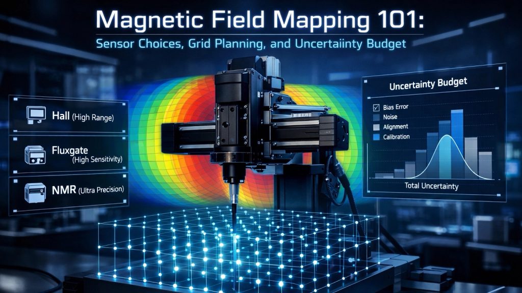
This article explains how to design a practical magnetic field mapping workflow,
from sensor selection to grid planning and uncertainty budgeting.
1. What Is Magnetic Field Mapping and Why It Matters
Magnetic field mapping is the process of measuring the spatial distribution of a magnetic field over a defined volume.
It is used to:
- Verify field uniformity specifications
- Define usable uniform volume
- Support acceptance testing and documentation
- Ensure reproducibility of experiments
Without mapping data, “uniformity” is only a theoretical promise.
2. Choosing the Right Magnetic Field Sensor
Sensor choice defines both measurement credibility and uncertainty floor.
2.1 Hall Sensors
Best for:
- mT to multi-Tesla fields
- General-purpose mapping
- Cost-sensitive setups
Limitations:
- Offset drift
- Temperature sensitivity
- Limited absolute accuracy without calibration
Hall probes are commonly used for routine acceptance mapping of electromagnets and Helmholtz coils.
2.2 Fluxgate Sensors
Best for:
- µT to low-mT fields
- Background field compensation studies
- Low-field uniformity verification
Advantages:
- Excellent low-field sensitivity
- Good stability over time
Limitations:
- Limited upper field range
- Sensitive to alignment errors
Fluxgates are ideal when Earth-field-level accuracy is required.
2.3 NMR Probes
Best for:
- Absolute field accuracy
- Reference calibration points
Advantages:
- Extremely high absolute accuracy
- Minimal drift
Limitations:
- Requires strong, homogeneous fields
- Not suitable for large-area scanning
NMR probes are often used to anchor uncertainty budgets rather than perform full mappings.
3. Grid Planning: How Many Points Are Enough?
Grid design determines whether mapping data is meaningful or misleading.
Key Principles
- Mapping resolution must match field gradient scale
- Uniform volume edges require higher point density
- Symmetry can reduce total point count
A common mistake is using too few points and assuming smooth interpolation.
Typical Grid Strategies
- 1D axis scans for quick checks
- 2D planar grids for aperture systems
- 3D volumetric grids for Helmholtz and vector coil systems
The larger the claimed uniform volume,
the more demanding the grid requirements become.
4. Positioning Error: The Silent Uncertainty Source
Positioning error often dominates the uncertainty budget.
Sources include:
- Probe holder tolerances
- Mechanical sag
- Manual placement repeatability
Even a 1 mm position error can produce significant field uncertainty in high-gradient regions.
Good mapping setups treat mechanical alignment as a first-class specification.
5. Repeatability and Temporal Stability
Field mapping is not a single measurement.
You must verify:
- Short-term repeatability
- Drift over time
- Sensitivity to coil temperature
Repeated scans at selected points are essential for validating stability claims.
6. Building an Uncertainty Budget
A credible field mapping report includes an uncertainty budget.
Typical contributors:
- Sensor accuracy and calibration
- Temperature effects
- Positioning uncertainty
- Measurement noise
- Current stability
Ignoring uncertainty does not remove it.
It only hides it.
7. From Mapping to Acceptance Testing
For procurement and system acceptance, mapping data should define:
- Uniform volume size
- Maximum deviation (% or ppm)
- Measurement conditions
- Repeatability metrics
This transforms “uniformity” from marketing language into a verifiable specification.
8. Practical Mapping Solutions and Services
Cryomagtech supports magnetic field mapping through:
- Helmholtz and electromagnet systems designed for accessible mapping
- Field mapping fixtures and probe holders
- Optional mapping data and acceptance documentation
👉 Product / Service link placeholder: Field Mapping Accessories & Acceptance Testing Support
References
- Wikipedia – Magnetic field measurement fundamentals
https://en.wikipedia.org/wiki/Magnetic_field - IEEE – Precision magnetic measurement techniques
https://ieeexplore.ieee.org/
Key Takeaways
- Field mapping is the only proof of uniformity
- Sensor choice defines accuracy limits
- Grid planning must match gradient scale
- Positioning errors dominate uncertainty
- Acceptance testing requires documented uncertainty
If you cannot explain how uniformity was measured,
you probably cannot defend it.